Vibrational Behavior of Three Floors
Structure Equipped with Dampers
Abstract-- Three floors building model made from carbon steel was tested in the current work to show its vibrational behavior under transient excitation. The main contribution of the current work is to show the effect on adding vibrational damper in first floor with numerous orientations on the vibrational modes, then studying the effect of adding second set of dampers on the second floor. Numerical and experimental analyses were carried out on the tested model for both modal and transient analysis.
Results show that the adding of vibrational damper will boost the ability of the tested structure to withstand against all modes of vibrations for all selected damper's orientation. Best enhancement in the vibrational modes of the tested structure was satisfied with adding double vibrational damper the orientation of 45˚ at first and second floor respectively.
Index Term-- Vibrational behavior; finite element analysis, three floors structures.
1. INTRODUCTION
There are basically four fundamental mechanisms of vibration control [1-7], which are: control of the natural frequencies in order to avoid resonance under external imposed loads, introduction of damping or any energy spendthrift mechanism, use of insulating elements in supports and/or bases that reduce force transmission, and the incorporation of dynamic vibration absorbers or vibration neutralizers. Several dynamic absorbers have been designed; some of them are based on the impact of a mass on the structure (IVA) [8], while others are used in aeronautical applications to minimize vibration and noise levels in the piloting cabin [9]. Many absorbers have been built to control wind [10] or seismic effects [11, 12] on structures. This last field becomes very important nowadays from the safety perspective in the increasingly more daring architectural engineering works. Chen et al. [13, 14] have carried out several contributions in structures damping and anti-seismic construction. Their experimental and numerical studies developed both for buildings and in transportation applications, are outstanding. These studies optimize construction through elements of seismic control, thus improving road safety. The analysis of the structural vibrations should include a dynamic analysis and a comparison of the predicted accelerations to the human allowances related to comfort, although simplified criteria may often be used based on the floor flexibility or the natural frequency. The issue of the economical design of service buildings with steel columns and steel and concrete composite floors was addressed by Costa [15], who performed a comparative study for varying steel grades and
the spans, where each structure was designed according to Eurocode 3 [16] and Eurocode 4 [17]. The design coped with the verifications of the ultimate limit states and the deformation limit state under service loads, and the steel weights for each type of element and for the whole structure were determined. In addition, Costa presented curves relating the various parameters and obtained trends for determining the optimum (economical) span [15]. A significant contribution to this field was made in Brazil by Alves [18] and Faísca [19] based on experiments made with a group of volunteers acting on a concrete platform. These tests enabled the development of approximated descriptions of the loads induced by human activities, such as jumping, aerobics, football (soccer), and audience responses to rock concerts. These tests were executed over two concrete platforms, one rigid and the other flexible, both of which were placed on movable supports, which allowed the structure stiffness to vary, enabling the investigation of the human rhythmic load over rigid or flexible structures. The experimental results and the obtained analytical model led to the development of load functions for synchronous and asynchronous activities that could be used in structural designs intended for stadiums and other similar structures. The main contribution of the current work is to show the effect on adding vibrational damper in first floor with numerous orientations on the vibrational modes, then studying the effect of adding second set of dampers on the second floor. Numerical and experimental analyses were carried out on the tested model for both modal and transient analysis.
2. FINITE ELEMENT MODELING
Structural engineers have developed matrix methods for the analysis of framed structures, which can be easily recognized as assemblages of elements, is connected together by nodes. The finite element method (FEM) can now be considered as the most popular numerical technique, and it has been successfully applied to many engineering analysis of solid and structures, computational fluid dynamics, heat transfer, tribology, electromagnetism, ……. etc. There are two different approaches can be followed for the formulation of the (FEM). Firstly, the direct variational method (Rayleigh-Ritz and energy method) and secondly, the weight residuals approach (Galerkin method). In the first approach, the fundamental equations are derived by calculation the total potential functional of the system and to invoke the stationarity of the functional, i.e. equal to zero.
Adawiya Ali Hamzah
M. Sc. (Applied Mechanics)
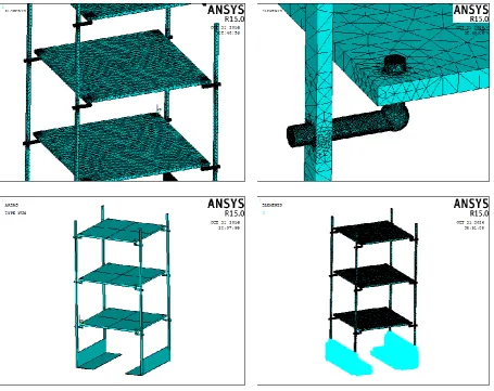
were carried out in ANSYS APDL15 environment where all the boundary conditions were simulated. Block lanczos method was used for estimating first interesting 3 mode of vibration for tested structure. While analysis type [Trans] was used with time step of 0.0005 sec for satisfying the pulse excitation that aimed to simulate earthquake. Lower bars with corresponding connecting plate were firmly fixed
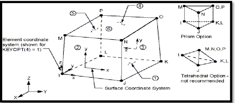
figure (2). In which different orientation for the tested structure besides the meshed model are presented. Three orientations for vibrational damper were selected to show their effect on the overall structural behavior for each mode, these orientations were 30˚, 45˚ and 60˚ counter clock wise respectively.
3. EXPERIMENTAL MODEL
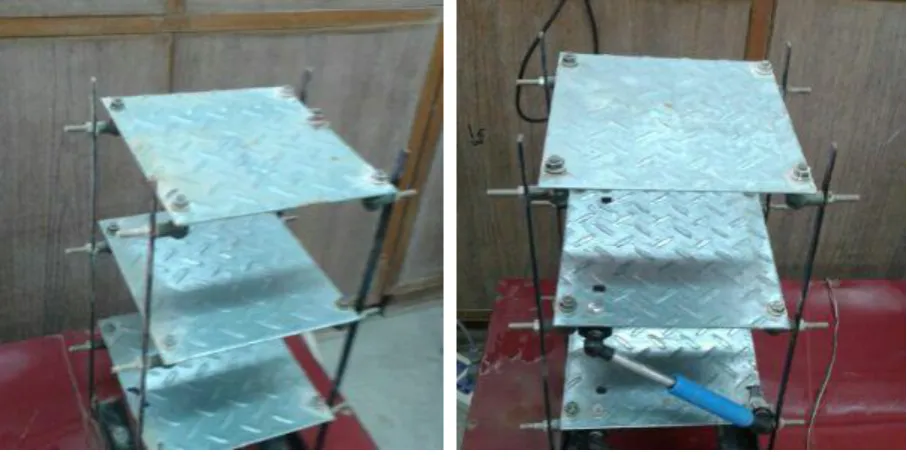
Scaled of three floors building was fabricated totally in laboratory. Three slabs of carbon steel were arranged in parallel to formulate floors from 1 to 3 respectively. Four bars fixed in vertical orientation with 90˚ to formulate the building border. High degree of accuracy
was satisfied to ensure high degree of agreement between experimental and numerical analysis. Experimental model of the current work is presented in figure (3)(a) in which model without damper is presented. In figure (3)(b), experimental
model with vibration damper is presented.
Fig. 4. Block diagram for testing elements used in measuring natural frequencies
Mechanical and chemical properties of material were estimated experimentally for the used material. Structural natural frequencies may be measured by applying steady state, shock loads to the structure. Through impact experimental test, is used to determine the frequency response functions which relate the response given by the specimen when loaded with a signal, allowing for the determination of the natural frequencies. The low velocity impact hammer is used to give the input load (shock) to the specimen. The block diagram in figure (4) shows how is a typical modern vibration meter built-up. The accelerometer is connected to charge amplifier which contains an amplifier
and high or low pass filters. The filters were built to limit the frequency range to the range of interest, thus reducing the possibility of interference from high and low frequency noise. The signal is analyzed by using wave record command. This is used to obtain the natural frequencies. Impact Hammer is shown in figure (5). The most appropriate mechanical device to excite linear structural system because it needs less instrumentation than others. Furthermore, its impact force has a short duration and can be considered as a pulse and the tip material could be chosen to excite preferably the low and medium natural frequencies. (a) Without damper (b) with damper
Fig. 5. Impact Hammer
The oscilloscope digital is of type (RIGOL DS1102E). This device is used to display the response waves result, extracted from the accelerometer, for the vibrating structures, see figure (6).
Fig. 6. Oscilloscope digital
Experimental modal analysis was performed as stated in figure (7) for both model without damper and for model with damper. All mentioned devices were utilized to carry out the experimental work after performing a high accurate calibration process for them. After collocating the results
they were compared with those estimated numerically. The comparison shows that the error between experimental and numerical results not exceeds 5% on average.
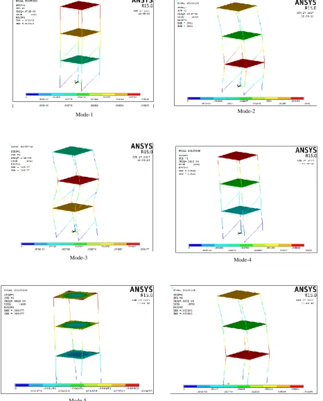
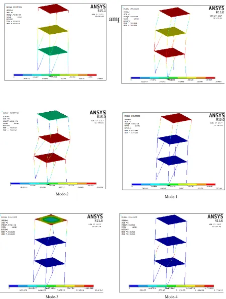
vibration dampers are presented. In figure (9, 10,11) first six modes of vibration measured numerically for the model with vibrational damper are presented with damper's orientation of30˚, 45˚ and 60˚ respectively.
From mentioned figure a comparison between experimentally measured modes and numerically measured one was performed for each mode. It was noticed that there was a little difference between both numerical and experimental results and this difference was not exceed the 5% threshold. This difference appears due to some external disturbances that may be effect on the tested structure. These differences may effect on the overall response of the
analysis.
5. CONCLUSIONS
Mode-5 Mode-3
Mode-2
Mode-4 Mode-1
Mode-6
Mode-5
Mode-3 Mode-4
Figure (10) Modes with damper- orientation of 45˚
Mode-3 Mode-2
Mode-4 Mode-1
[5] B. Chen and Y.L. Xu. Integrated vibration control and health monitoring of building structures using semi-active friction
dampers: Part ii-numerical investigation. Eng Struct, 30(3):573–
587, 2008.
[6] J.J. Wu. Use equivalent damper method for free vibration
analysis of beam carrying multiple two degree-of-freedom
spring-damper-mass systems. J Sound Vib, 281(1-2):275–293,
2005.
[7] S.D. Xue, J.M. Ko, and Y.L. Xu. Tuned liquid column damper
for suppressing pitching motion of structures. Eng Struct,
22(11):1538–1551, 2000.
[8] S. Ekwaro-Osire, C. Ozerdim, and M.P.H. Khandaker. Effect of
attachment configuration on impact vibration absorbers. Exp
Mech, 46:669–681, 2006.
[9] Y.H. Huang and C.C. Chen. Optimal design of dynamic
absorbers on vibration and noise control of the fuselage. Comput
Struct, 76(6):691–702, 2000.
[10] F. Fischer. Wind-excited vibrations-solution by passive dynamic
vibration absorbers of different types. J Wind Eng And Aerodyn,
95(9-11):1028–1039, 2007.
[11] A. Ghosh and B. Basu. Seismic vibration control of short period
structures using the liquid column damper. Eng Struct,
26(13):1905–1913, 2004.
[12] C.C. Lin, L.Y. Lu, G.L. Lin, and T.W. Yang. Vibration control
of seismic structures using semi-active friction multiple tuned
mass damper. Eng Struct, 32(10):3404–3417, 2010.
[13] J. Park and D.L. Palumbo. Damping of structural vibration using
lightweight granular materials. Exp Mech,49(5):697–705, 2009.
[14] Y.L. Xu, W.L. Qu, and B. Chen. Active/robust moment
controllers for seismic response control of a large span building
on top of ship lift tower. J Sound Vib, 261(3-5):277–296, 2003.
[15] Costa CSS. Estudo Ecomico de estrutura mistas contraventadas
de aço-bet[M.Sc. dissertation], Coimbra, Portugal: DEC-FCTUC, University of Coimbra; p.1–76 [in Portuguese].
[16] Eurocode 3. EN 1993-1-1. Design of steel structures – part 1. 1:
General rules and rules for buildings. Brussels, CEN-European committee for standardization; 2005.
[17] Eurocode 4. EN 1994-1-1. Design of steel and concrete
composite structures – part 1. 1: General rules and rules for
buildings. Brussels, CEN-European committee for
standardization; 2005.
[18] Alves NKC. Cargas dinâmicas devido a pessoas em movimento,
Rio de Janeiro, RJ, Brasil: Dissertaç de Mestrado – COPPE/UFRJ; 1997 [in Portuguese].
[19] F. RG. Characterization of dynamic loads due to human