IJIRT 147130
INTERNATIONAL JO URNAL OF INNOVATIVE RESEARCH IN TECHNOLOGY292
Study on the Modulus of Rupture Behavior of RCC and
R/ECC Beams
Mrs.A. Malliha
Lecturer (Senior Grade)/ Civil,Architecture Department , Ayya Nadar Janaki Ammal polytechnic
College, sivakasi
Abstract- Engineered cementitious composite (ECC) is a unique type of high performance fiber reinforced concrete possessing high ductility by significant strain hardening property under tension with steady state multiple cracking behavior. It was basically developed for applications in seismic resistant structures, energy absorption devices, repairing and retrofitting of concrete structural elements, as it attains adequate strength, deformation capacity and damage tolerance. The ductile property of ECC is in contrast to that of normal and high strength concrete, which is brittle in nature. The ingredients used for preparing ECC are cement, sand, fibers, mineral admixtures, chemical admixtures and water. In the present study, ECC is developed using Recron 3s polyester fibers, M sand passing through 300μ and retained on 150μ sieve and 53 grade cement 30% of which is replaced by fly ash thus promoting sustainability. Fly ash, an air pollutant is a waste product generated by thermal power plants where coal is used as fuel. The performance of R/ECC and RCC control beams in flexure under two point loading is compared in the present work. Cracking pattern, characteristics of the cracks developed, load deformation characteristics, first crack load, ultimate load and corresponding displacements are taken into account for analysis and comparison. From the study, performance of R/ECC beams is better than that of RCC beams and the ultimate load and deformation of R/ECC beams are greater than that of RCC control beams under flexural load.
Index Terms- Engineered cementitious composites,
ECC, Fiber reinforced concrete, Reinforced engineered cementitious composites, R/ECC.
I. INTRODUCTION
This Remarkable advancement in the development of high performance cementitious materials has taken place in the past few years, which include high strength concrete (HSC) with low water/binder ratio, high performance fibre reinforced cementitious
composites (HPFRCC) that exhibit improved strength and ductility. Over the last couple of decades, therehas been a growing interest among researchers to develop strain hardening fibre reinforced cementitious composites (SHFRCC) and Engineered cementitious composite (ECC) is one of the most significant developments in this field. Ductility attained by strain hardening makes ECC suitable for earthquake resistant structures. The structural elements using ECC are expected to reduce the seismic response and damages to the structures subjected to unexpected heavy reversible loads. Ingredients used in ECC are cement, sand, fiber, mineral admixtures, chemical admixtures and water. Unlike FRC or HPFRCC, ECC adopts fiber volume fraction even less than 2%. Coarse aggregate is eliminated as it affects the ductility of the composite. ECC could attain tensile strain capacity of 3% or more and tensile strength ranging from 3 to 6MPa. The compressive strength of ECC is in the range of 30-100MPa. The crack width of ECC is less than 200μm and the crack spacing is less than 2mm. The fiber, cementitious matrix, and the interface properties must be of a correct combination in order to attain the ductile behavior of ECC. To achieve the composite performance of ECC, high ductility and strain hardening need to be attained. To attain strain hardening behavior steady state multiple cracking is to be achieved, if not the material failure will be localized [8].
Due to the ultra-ductilebehavior it has many structural applications especially in earthquake resistant structures which include use of ECC in beam-column connections, blast resistant structural elements, etc. [10].
IJIRT 147130
INTERNATIONAL JO URNAL OF INNOVATIVE RESEARCH IN TECHNOLOGY293
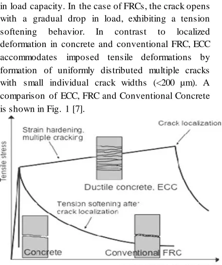
The behavior of ECC is different from conventional concrete or fiber reinforced concrete (FRC) which fails bysingle localized crack. In the case of ordinary cement concrete, the crack widens with a rapid drop in load capacity. In the case of FRCs, the crack opens with a gradual drop in load, exhibiting a tension softening behavior. In contrast to localized deformation in concrete and conventional FRC, ECC accommodates imposed tensile deformations by formation of uniformly distributed multiple cracks with small individual crack widths (<200 µm). A comparison of ECC, FRC and Conventional Concrete is shown in Fig. 1 [7].
Figure 1:Difference of ECC from Conventional FRC and Concrete
III. INTERACTION BETWEEN STEEL REINFORCEM ENT AND ECC
In steel reinforced ECC (R/ECC), both steel and the ECC are elastic-plastic materials capable of sustaining deformation up to several percent strain. The bond between ECC and steel reinforcement is not critical as in normal RCC, since stress can be transmitted directly through the ECC even after micro cracking.
IV.PREPA RATION OF PCC AND ECC TRIAL MIXES
To develop ECC mix, cement fine aggregate ratio was selected as 1:0.5, and the fiber volume fraction was varied from 0.5% to 1.5%. Fine aggregate used is M sand passing through 300μ and retained on 150μ IS sieve. Three different mixes were prepared for ECC, using fiber volume fractions of 0.5%, 1.0% and
1.5% (ECC-0.5, ECC-1.0 and ECC-1.5). PCCmix was also prepared as per IS 10262-2009 to compare its fresh and hardened properties with that of ECC mix with same compressive strength. To study the mechanical properties of PCC and ECC mixes, cubes, cylinders and prisms 3 each were cast for each mix. The test results of M30 ECC trial mixes and M30 PCC mix are shown in the tables II and III respectively.
A. Tests on Constituent Materials 1) Cement:
Cement used in all mixes were Ordinary Portland Cement (53 grade), which conforms to IS specification [3]. The standard consistency of cement used is 33%.
2)Fine Aggregate:
Commercially available M Sand passing through 4.75mm IS sieve and conforming to zone II of IS 383-1970 was used for PCC and M sand passing through 300μ and retained on 150μ IS sieve was utilized for ECC. All physical properties were determined as per IS recommendations [4]. Specific gravity and fineness modulus of M Sand are 2.45 and 2.56 respectively.
3) Coarse Aggregate:
The properties of coarse aggregates used for preparing PCC conformed to the IS specification [5]. Specific gravity and fineness modulus are 2.88 and 6.92 respectively.
4) Fly Ash:
F class fly ash with 59.42% silica content was used for the ECC mixes.
5)Superplasticizer (SP):
The superplasticizer used for developing ECC trial mixes is structure 402.
6) Fibers:
IJIRT 147130
INTERNATIONAL JO URNAL OF INNOVATIVE RESEARCH IN TECHNOLOGY294
of fiber obtained from manufacturer are shown on table I.
Property Specifications
Chemical Composition Modified Polyester
Cross-Section Triangular
Diameter Micron 30-40
Elongation (%) >100
Cut Length (mm) 12
Moisture flat (%) < 1.0
Melting Point (°C) 240-260
Softening Point (°C) 220
Specific Gravity, (g/cc) 1.35
Table I: PROPERTIES OF RECRON 3S FIBRE
7)Reinforcement:
HYSD bars with 8mm and 6mm diameter were used as the main reinforcement and stirrups respectively for the beams. The steel bars were tested to determine its mechanical properties. The yield strength of 6mm and 8mm bars are 465.82N/mm2 and 428.13 N/mm2 respectively.
Materials ECC 0.5 ECC 1.0 ECC 1.5
Cement (kg/m3) 847 847 847
Fly ash (kg/m3) 363 363 363
Sand (kg/m3) 604.8 604.8 604.8
Fiber (%) 0.5 1.0 1.5
Water (kg/m3) 423.3 423.3 423.3 Superplasticizer
(kg/m3)
12 12 12
Table II: ECC MIX PROPORTION
Materials Mass (kg/m3)
Cement 450
Fine aggregate 598.3
Coarse aggregate 1112.3
Water 207
Table III :MIX PROPORTION FOR NORMAL CONCRETE AS PER IS 10262:2009
Cube compressive strength, split tensile strength, flexural strength and modulus of elasticity of the 3 ECC trial mixes and PCC were determined as per IS standards. The test results are given in the tables IV and V.
Property (N/mm2) ECC-0.5 ECC-1.0 ECC-1.5
Cube compressive
strength
30 32 28
Split tensile strength 3.5 4.8 4.2
Flexural strength 4.06 6.13 5.39
Modulus of elasticity 3.22x10⁴ 4.51x10⁴ 3.96x10⁴
Table IV: PROPERTIES OF ECC
Property Test Result
Cube compressive strength (N/mm2) 32
Split tensile strength (N/mm2) 2.12
Flexural strength (N/mm2) 3.33
Modulus of elasticity (N/mm2) 3.22x10⁴
Slump (mm) 110
Table V: FRESH AND HARDENED PROPERTIES OF PCC
The properties of ECC trial mixes were compared and ECC-1.0, containing 1% fiber volume fraction was selected as the optimum mix as it attained the maximum compressivestrength and split tensile strength. The cube compressivestrength and split tensile strength obtained for ECC-1.0 are 32 N/mm2 and 4.8 N/mm2 respectively. Thus ECC-1.0 mix was taken for further study. R/ECC beams using ECC-1.0 mix and RCC control beams using M30 mix were cast for comparing their performances under two point loading.
V.EXPERIM ENTA L INVESTIGATIONS ON R/ECC AND RCCCONTROL BEAMS
Experimental investigation was conducted to compare flexural behavior of two series of R/ECC and RCC beams. Two beams each of R/ECC (R/ECC1, R/ECC2) and RCC (RCC1, RCC2) of dimensions 150x150x700mm, reinforcement ratio 0.23% and shear span 167mm were cast. The minimum reinforcement was provided based on IS code [6]. Fig. 2 shows the reinforcement details and dimensions of beams.
Figure 2: Dimensions and reinforcement details of beams
IJIRT 147130
INTERNATIONAL JO URNAL OF INNOVATIVE RESEARCH IN TECHNOLOGY295
loading in a 200t UTM, after 28 days of curing. The schematic diagram and test setup for two point flexural loading are shown in Figs. 3 and 4.
Figure 3:Schematic diagram of the test setup
Figure 4: Experimental setup for two point flexural loading
The load was applied using hydraulic jack and was measured with a load cell of least count of 0.2 t. The mid span deflections were measured using dial gauge of 0.01mm least count for every 0.2 t increment of load. The first crack load, ultimate load and maximum deflection were noted. The crack patterns of R/ECC beams was analyzed and compared with that of RCC control beams. The first crack load and ultimate load of all the beam specimens are tabulated in table VI.
SPECIMEN First crack load (kN)
Ultimate load (kN)
R/ECC1 48 124
R/ECC2 45 118
RCC1 31 105
RCC2 32 85
Table VI: COMPARISON OF FIRST CRACK LOAD AND ULTIMATE LOAD
R/ECC beams obtained higher first crack load and ultimate load than those of RCC control beams. The first crack load and ultimate load of R/ECC1 beam are 54% and 18% respectively more than those obtained for RCC1 beam. The first crack load and ultimate load of R/ECC2 beam are 41% and 39% respectively more than those obtained for RCC2 beam.
While loading the beams, the mid span deflections were measured using a dial gauge, for each load increment of 0.2t.The load-deflection data obtained was utilized to plot the curve shown in Fig 5.
Figure 5:Load-deflection plot for RCC and R/ECC beams
VI.CRACKS AND FAILURE PATTERN
From the load-deflection plot it is clear that R/ECCbeams have better load carrying capacity than RCC beams.The mid span deflections of R/ECC beams are greater thanthose of RCC beams and the mid span deflections of R/ECC1and RCC1 beams are 3.2 and 3.04 mm respectively.
IJIRT 147130
INTERNATIONAL JO URNAL OF INNOVATIVE RESEARCH IN TECHNOLOGY296
Fig. 6 shows the crack pattern of R/ECC1 and RCC1 beams after testing. The crack width and minimum and maximum crack spacing were measured using a crack detection microscope of least count 0.02 mm. In RCC beams two major cracks were noticed and the beams failed in flexure after the widening of the cracks. But in R/ECC beams several micro cracks were formed on loading and the beams failed without the widening of the cracks. The hair line cracks traversed up to the top of the R/ECC beams, most of which developed between the loading faces.
The crack formation details of the beams after testing are given in table VII. Number of cracks formed in RCC beam was 2 but in R/ECC beams 12 micro cracks were formed. The crack width was higher in RCC beam but in R/ECC beam the minimum crack width was less than 0.02mm.
Description RCC1 R/ECC1
No. of cracks formed 2 12
Maximum spacing between cracks (mm)
95 100
Minimum spacing between cracks (mm)
65 3
Max Crack width (mm) 4 0.1
Minimum crack width (mm) 0.08 <0.02
Table VII: DETAILS OF THE CRACKS
DEVELOPED ON THE TESTED SPECIMENS
VII. CONCLUSION
The flexural strength and behavior of R/ECC and RCC beams of same grade and same reinforcement ratio are compared in this study. From the experimental investigation, the following conclusions are drawn.
1. The hardened properties of ECC were superior to that of PCC of same grade. The split tensile strength and flexural strength were higher by 126% and 84% respectively for ECC-1.0 beam compared to those for PCC. Modulus of elasticity of ECC- 1.0 is 40% greater than that for PCC.
2. The first crack load and ultimate load of R/ECC beams are more than RCC beams. The first crack load and the ultimate load of R/ECC1 beam is 54% and 20% respectively higher than those for the RCC1 control beam.
3. On loading, several micro cracks were formed in R/ECC beams but in RCC beams only two cracks were formed before the brittle failure. The minimum crack width of RCC beams was 0.08 mm and that of R/ECC beams is less than 0.02mm.
4. The formation of multiple cracks increases the ductility of the structural elements and enables them to reduce the seismic damages because of the prevention of catastrophic failures as in case of RCC structures.
From the above findings, it can be concluded that the hardened properties, load carrying capacity and ductility of R/ECC is more than RCC and it will reduce the structural seismic response and damage. Since the width of cracks is less than 0.3mm, serviceability requirements are also met even though several hair line cracks are formed. ECC elements can thus face the durability challenges of the environment also.
REFERENCES
[1] E.H. Yang, Y. Yang, V.C. Li” Use of high volumes of fly ash to improve ECC mechanical properties and material greenness” ACI Materials Journal vol.104 , No.6 , pp.620–628, May 2007
[2] IS 10262-2009, Concrete Mix Proportioning - Guidelines, Bureau of Indian Standards, New Delhi
[3] IS 12269-1987 Indian Specification for 53 grade Ordinary Portland Cement Indian Standard Code on Properties of Cement
[4] IS 383-1970, Specification for Coarse and Fine Aggregates from Natural Sources for Concrete (Second Revision)
[5] IS 2386 Part III-1963, Methods of Test for Aggregates for Concrete Part 3- Specific gravity, Density, Voids, Absorption and Bulking
[6] IS 456 : 2000, “Indian standard code of practice for plain and reinforced concrete”, Bureau of Indian Standards, New Delhi
IJIRT 147130
INTERNATIONAL JO URNAL OF INNOVATIVE RESEARCH IN TECHNOLOGY297
[8] Li, V.C. and Leung C.K.Y (1992) “Steady State And Multiple Cracking Of Short Random Fibre Composites”, ASCE J. of Engineering Mechanics, 118(11), pp. 2246-2264.
[9] Li, V.C., Mishra, D.K., Naaman, A.E., Wight, J.K., LaFave, J.M., Wu, H.C. and Inada,Y “ On
the Shear Behavior Of Engineered
CementitiousComposites ”,Advanced Cement Based Materials, vol.1, No.3, pp. 142- 149, Aug. 2003.
[10]Li, V.C. (1997) "Engineered Cementitious Composites (ECC) - Tailored Composites through Micromechanical Modeling", Fiber Reinforced Concrete: Present and the Future, Eds: N. Banthia, A. Bentur, and A. Mufti, Canadian Society of Civil Engineers.
[11]Park R and Paulay T (1975) “Reinforced concrete structures”, John Wiley Sons, New York
[12]Rathod J. D. and Patodi S. C(2008) “ Engineered Cementitious Composites at a glance”, Construction magazine
[13]Rathod J. D. and Patodi S. C(2010) “A comparative study of Recron and steel fibre
reinforced Engineered Cementitious
Composites”, Construction magazine
[14]Rathod J. D. and Patodi S. C (March-April 2010) "Interface Tailoring of Polyester- Type Fibre in Engineered Cementitious Composite Matrix against Pull Out", American Concrete Institute (Materials) Journal, Vol. 107, No. 2, pp. 114-122.
[15]S. Wang, V.C. Li, Engineered Cementitious Composites with high- volume fly ash, ACI Materials Journal, Vol. 104. No. 3, pp. 233– 241.May 2007
[16]T.Kanda , S. Watanabe, V.C. Li “Application of pseudo strain hardening cementitious composites to shear resistant structural elements”