International Journal of Engineering & Technology IJET-IJENS Vol:10 No:06 89
Machine Vibration Analysis for Determining
Optimum Operational Engine Speed
Gatot Pramuhadi, Mad Yamin, and Siti Khoirunnisa
Department of Biosystem and Mechanical Engineering, Faculty of Agricultural Engineering and Technology,
Institut Pertanian Bogor, IPB Darmaga Campus PO Box 220 Bogor 16002 E-mail: [email protected]
Abstract
--
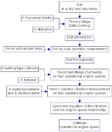
The objective of the research was to analyse the amount of machine vibration and to approximate an optimum operational engine speed. The research was conducted on March 2009 until July 2009 in a dry field laboratory, Department of Biosystem and Mechanical Engineering, IPB, Bogor, West Java, Indonesia. Four operational engine speeds were applied to the five horsepower gasoline engine walking type cultivator and the amount of vibration on operator’s hand was measured. When cultivator is operated on engine speeds of 1000 rpm, 1250 rpm, 1500 rpm, and 2000 rpm showed in variation of vibration on operator’s hand. The vibration increases from 1000 rpm to 1250 rpm and then it decreases when the engine speed is increased after 1250 rpm up to 2000 rpm. The curve of the engine speed and the vibration relationship shows a polynomial equation. The equation is Y = - 8.464 + 0.03196 X - 0.000012 X2, where Y is vibration (m/s2) and X is engine speed (rpm). Based on the equation, it can be calculated that the highest vibration (12.816 m/s2) is on 1330 rpm. Engine power is multiplication of torque and engine speed. Generally, a machine is operated on maximum torque for the best performance. When it is on that maximum torque, the machine vibration will be in maximum too. Based on the equation and the calculation, it can be approximated that optimum operational engine speed for soil cultivating is 1330 rpm. On that engine speed range, theoretically engine torque is in maximum range too. So, it can be recommended that the machine (i.e. the walking type cultivator) must be operated on engine speed range of 1330 rpm.Background
In Indonesia, farm machinery always needed to increase effectiveness and efficiency on all farm fields. It can be achieved by applying high quality machines that had high pleasantness and safety.
An engine operated a machine. Generally, the engine was arranged on optimum crankshaft speed to obtain maximum torque in order to get maximum machine performance. During the operation, it appears vibrations from the engine, machine components, and interaction between the machine and other medias. It will influence the machine performance and especially toward operator’s pleasantness and safety.
Generally, an engine performance was measured by a dynamometer to find out an engine characteristic curve. The
Objective
The objective of the research was to analyze the amount of machine vibration and to approximate an optimum operational engine speed.
Methods
The research was conducted on March 2009 until July 2009 in a dry field laboratory, Department of Biosystem and Mechanical Engineering, Institut Pertanian Bogor (IPB), Bogor, West Java, Indonesia.
Main research variables, which are used to analyze the amount of machine vibration and to approximate an optimum operational engine speed, are:
1. Vibration on hand’s, or arm’s, of operator 2. Engine speed.
Machines, tools, and instruments for conducting research consisted of:
1. one unit of walking type cultivator (5 hp gasoline engine, 2000 rpm)
2. one unit of four-wheel tractor 3. a vibration meter
4. a digital tachometer 5. a furrower (ridger) 6. a disk plow
7. some soil sampler rings 8. an oven.
Fig. 1. A schematic diagram of research design to approximate an optimum engine speed
International Journal of Engineering & Technology IJET-IJENS Vol:10 No:06 91
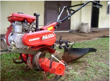
Fig. 2. The walking type cultivator with the furrower
Fig. 3. The machine vibrations measurement on stationary condition
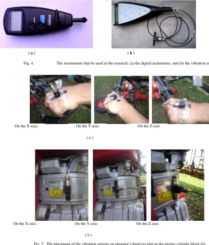
Fig. 4. The instruments that be used in the research: (a) the digital tachometer, and (b) the vibration meter
Fig. 5. The placement of the vibration sensors on operator’s hand (a) and on the engine cylinder block (b)
( a ) ( b )
On the X-axis On the Y-axis On the Z-axis
( a )
On the X-axis On the Y-axis On the Z-axis
International Journal of Engineering & Technology IJET-IJENS Vol:10 No:06 93
Fig. 6. The machine vibrations measurement in the field
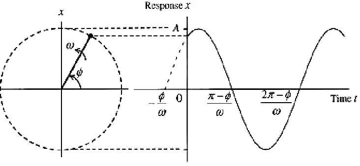
Fig. 7. A sinusoidal vibration illustration (Sanders and Cormick, 1987)
Equations which be used to explain vibration in an acceleration unit were equation 1, equation 2, equation 3, and equation 4 below. Total vibration acceleration is shown in equation 5.
A
t
y
sin
……… (1)
A
2sin
t
……….…….. (3)y
2
……….…….….…… (4)2 2 2
= initial angle, rad
v = velocity, m/s
a = vibration acceleration, m/s2
ahav = resultant of vibration acceleration, m/s2
aX = vibration acceleration on X - axis, m/s2
aY = vibration acceleration on Y - axis, m/s2
on 0 cm up to 30 cm depth, so that the soil condition before soil cultivating is uniform. It means that effect of the soil condition toward the machine performance is uniform too, so that the research results were influenced by the arrangement of the four engine speeds.
Table I
Vibration acceleration on the engine cylinder block and on the operator’s hand
Engine
speed,
rpm
Vibration acceleration, m/s
2On the engine cylinder block
On the operator’s hand
a
Xa
Ya
Za
hava
Xa
Ya
Za
hav1000
1.49
1.10
2.28
2.94
8.07
6.23
5.44
11.55
1250
2.23
1.59
2.73
3.86
8.75
5.85
7.07
12.68
1500
4.10
1.92
3.95
6.00
8.22
5.38
7.88
12.59
2000
-
-
-
-
4.27
4.21
4.56
7.53
The calculation of vibration acceleration on the engine cylinder block and on the operator’s hand is shown at Table I above. Vibration measurement on the engine cylinder block was conducted stationary, whereas vibration measurement on the operator’s hand was conducted in the field during the machine operation. Engine vibration measurement was just up to 1500 rpm, because there was any trouble when it applied up to maximum engine speed (2000 rpm) that is the sensor cannot stick or adhere to the engine cylinder block.
Table I showed that vibration on the operator’s hand is higher than on the engine cylinder block. It can be understood that the operator’s hand vibration is a resultant vibration that it is influenced by vibration from the source of vibration i.e. engine and the tool (furrower) vibrations transmitted to the machine handlebar and the operator’s hand, so that it will result in vibration amplitude.
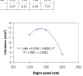
The machine is the five horsepower gasoline engine, which has 2000-rpm maximum engine speed. When it is operated on engine speeds of 1000 rpm, 1250 rpm, 1500 rpm, and 2000 rpm showed in variation of vibration on the operator’s hand. It can be seen in Figure 8.
Fig. 8. Relationship between operator’s hand vibration and engine speed
International Journal of Engineering & Technology IJET-IJENS Vol:10 No:06 95 equation, it can be calculated that the highest vibration (12.816
m/s2) is on 1330 rpm.
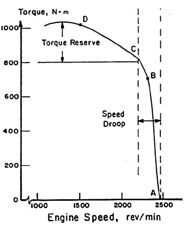
The curve, as seen in Figure 8, can be connected to the curve of relationship between engine speed and engine
torque of a tractor (Figure 9). It seem that the both curves have the same characteristic. So, we can state that there is any relationship between vibration and engine torque.
Fig. 9. Relationship between engine speed and engine torque of a tractor (Srivastava, 1993)
Engine power is multiplication of torque and engine speed. Understanding the relationship between torque, power, and engine speed is vital in automotive engineering, concerned as it is with transmitting power from the engine through the drive train to the wheels.The gearing of the drive train must be chosen appropriately to make the most of the
0.000012 X2, where Y is vibration (m/s2) and X is engine speed (rpm). Based on the equation, it can be calculated that the highest vibration (12.816 m/s2) is on 1330 rpm, so that 1330 rpm is an approximation of optimum operational engine speed.
Suggestions
It can be recommended that the machine (i.e. the walking type cultivator) must be operated on maximum engine torque, which it will result in maximum vibration. Based on this research, it can be develop for further analysis, for example: it is connected or linked with safety toward operator, i.e. operator’s endurance because of machine vibration and noise.
REFERENCES
[1] De Silva, Clarence W. 2000. Vibration: Fundamental and Practice. Boca Raton: CRC Press LLC
[2] [European Union]. 2002. European Directive 2002/44/EC of the European Parliament and Council, Official Journal of European Communities. 6.7. L 177/13
[3] [European Union]. 2006. Guide to Good Practice on Hand Arm Vibration V7.7
[4] Goglia, V., Z. Gospodaric, D. Filipovic, D. Igor. 2006. Influence on Operator Health of Hand-Transmitted Vibrations front Handles of a Single-Axle Tractor. Journal Agriculture Environmental. 13. Page: 33 – 38
[5] Jones, F. R. 1963. Farm Gas Engines and Tractors. McGraw-Hill, Inc. New York, USA
[6] Khoirunnisa, S. 2009. Vibrations and Noise Analysis on Walking Type Cultivator Operation. [Undergraduate thesis]. Bogor: Faculty of Agricultural Engineering and Technology, Institut Pertanian Bogor
[7] Lache, S. 2007. Complex Study on Hand-arm System Exposed to Vibrations. Journal. Issue 11. Volume 2. Page 215-227 [8] Pramuhadi, G. 2005. Optimum Soil Tillage on Dry Land
Sugarcane Cultivation. Dissertation. Postgraduate School, IPB, Bogor
[9] Sakai, 1998. Two-Wheels Tractor. IPB Press, Bogor
[10] Sanders, M.S. and E.J. McCormick. 1987. Human Factors in Engineering and Design. Sixth Edition. McGraw-Hill, Inc. New York, USA
[11] Singleton, W.T. 1972. Introduction to Ergonomic. World Health Organization, United Nation, Geneva, Switzerland