112304-7676 IJET-IJENS @ August 2011 IJENS I J E N S
Study of Enhancing the Swirl Burner
Performance On a Small scale Biomass
Gasification
Adi Surjosatyo
1and Farid Nasir Ani
21
Department of Mechanical Engineering, Faculty of Engineering University of Indonesia, 16424 Depok, Indonesia
2Faculty of Mechanical Engineering Universiti Teknologi Malaysia
Karung Berkunci 791, 81310 Johor Bahru Johor DT, Malaysia Corresponding author: adisur@eng.ui.ac.id
Abstract
--
There are many processes for converting biomass into a more useful form of energy. One of the most popular technological processes is through direct combustion of biomass or in a controlled atmosphere or gasification. The current gasifier that has a maximum heat capacity of combustion system of 15.02 kW, used to burn biomass (oil palm shell) produces gases of low calorific gas through a low calorific swirl gas burner. Some problem appears using low calorific, it causes no circulation and weak swirling flame, and this will be an increase of residence time at high temperature. The gas burner, which is incorporated with the two-stage biomass combustion system, consists of burner tube and swirl-vane. These swirl gas burners that consist ofdifferent turning vane positions i.e. 20o, 30o and 40o, are equal to
the swirl number of 0.22, 0.356 and 0.508, respectively. The experimental shows that maximum heat release of the gas burner is 5.8 kW at equivalence ratio of 1.21 with the gas flow rate of 1.04 g/hr. The flame temperature of the gas burner reached a
range of 590 to 677 oC at the equivalence ratio, of 1.16 to 1.66.
In case of swirl flames while increased the swirl number, the flame length decreased significantly with the increasing premixing and flame changed from orange-yellow color to a blue color as the characteristics of a higher level of premixing.
Index Term-- Gas burner, Swirl Burner Performance, biomass gasification, swirl flame
1. INTRODUCTION
On acquiring the best performance of gas burner, it is necessary to find a design of gas burner so that the combustion efficiency can be increased. And also, currently, the reduction of pollutant emissions from practical combustion devices is a major issue in combustion research. One of the main pollutants is NOx and CO. Therefore, some different methods
have been proposed to reduce these emissions. These include, for example, partially premixed turbulent flames [1], rotating matrix swirl burner [2], heat recirculation ceramic burner [3], air swirl burner [4] , tangential inlet swirl burner [5], air staging [6], reburning and low NOx burners. In general, these
methods try to reduce the residence time in high temperature regions or to avoid high oxygen concentration in such regions. Some previous study [6,7,8,9] mentioned, gas turbine combustors and industrial systems utilized a high-swirl type of burner in which the swirling motion generated by the injector (or burner) is sufficiently high to produce a fully developed
internal recirculation zone at the entrance of the combustor. For conventional non-premixed combustion, the role of the large recirculation zone, also known as the toroidal vortex core, is to promote turbulent mixing of fuel and air. In premixed systems, the recirculation zone provides a stable heat source for continuous ignition of the fresh reactants, as refers to the review of Syred and Beer [7] for extensive background on the basic processes and practical implementation of high-swirl combustors7.
But according of some study [10.11], low-swirl combustion is a relatively recent development, is an excellent tool for laboratory research on flame/turbulent interactions. Its operating principle exploits the “propagating wave” nature of premixed flames and is not valid for non-premixed combustion. Premixed flames consume the reactants in the form of self-sustained reacting waves that propagate at flame speeds controlled by mixture compositions, thermodynamic conditions, and turbulence intensities. In contrast, non-premixed diffusion flames do not propagate (i.e., move through the reactants) because burning occurs only at the mixing zones of the fuel and oxidizer streams. To capture a fast moving turbulent premixed flame as a “standing wave” that remains stationary, low-swirl combustion exploits a fluid mechanical phenomenon called a divergent flow. As the name implies, divergent flow is an expanding flow stream. It is formed when the swirl intensities are deliberately low such that vortex breakdown, a precursor to the formation of flow reversal and recirculation, does not occur. Therefore, the Low Swirl Combustion (LSC principle is fundamentally different from the high-swirl concept of typical Dry Low NOx (DLN)
gas turbines, where strong toroidal vortexes are the essential flow elements to maintain and continuously reignite the flames. The engineering guideline for the LSB is specified in terms of a range of swirl number (0.4 < S < 0.55).
112304-7676 IJET-IJENS @ August 2011 IJENS I J E N S
generating a recirculation bubble which plays an important role in flame stabilization. There are two main requirements for flame stabilization, first, mixture ratios within
flammability limits and second, velocities low enough to match burning velocities.
Fig. 1. The gas burner tube inserted with a 20o vane pack swirler
Swirl significantly influences heat and mass transfer in many natural and technological flows [12]. Swirl is used in vortex burners and chemical reactors to stabilize the flame front and to increase the surface area across which heat and mass transfer exchange occurs. In vortex devices, centrifugal acceleration can be high as 104 times the gravity and provides useful stratification of temperature and density. Hot low-density fluid collects near the axis of rotation, i.e. away from side-walls, while the near-wall region consists of cold high density fluid.
In waste and fuel burners and within furnaces, swirl is often used to modify flow characteristics. Because of the intense recirculation patterns in swirling flows (burning gases travel back towards the burner bringing heat energy and reactive species to promote ignition in entering fuel-air mixture) rotation is found to shorten the flame [13].
2. EXPERIMENTAL PROCEDURE
The current swirl burner is the upper part of the complete combustion system that was fabricated in the
combustion laboratory. The fuel-gas in the gas burner is produced by the gasifier, the lower part of the combustion system.
Mixing gas will be ignited in the secondary chamber, which has dimension of 0.3 m diameter and 0.35 m length. It was constructed from 1 mm mild steel-plate. Because of the present gasifier is a pilot scale facility, the chamber was not necessary lined with the refractory since this facility was not utilized for a long operation. However, the best furnace chamber should be lined with refractory to prevent excessive heat loss.
The producing gas from the primary chamber was kept constant around 1.04 g/hr. For the secondary air, its flow rate was varied from 438, 498, 535 and 622 lpm. The operating conditions for the turbulent premixed flames considered in the present study are summarized in Table 1. The nominal heat release rate is obtained by multiplying the fuel mass flow rate by its nominal heating value of 5100 kJ/m3 [14].
Table I
Operating Conditions for Turbulent Premixed Flames
Flow Parameter
Swirl-vane angle
20
o30
o40
oEquivalence Ratio, -
1.16 – 1.66
Nominal heat Release, kW
5.8
Gas flowrate, g/hr
1.04
Flame Temperature,
oC
560
569
632
Temperature at burner exit,
oC
244
253
284
Range of secondary air flowrate, lpm
438 - 622
112304-7676 IJET-IJENS @ August 2011 IJENS I J E N S
2.1 Instrumentation Set-Up
Figure 2.a and 2.b show the configuration of the combustion system and enlargement of secondary chamber, respectively. The flowmeter used was ventury type and before utilized for the air flowrate measurement (primary and
secondary air supply), it was calibrated with the standard flowmeter. Adjusting the air supply consumption, two air valves were mounted on each air-supply pipes. Measuring the air flowrate can be done directly through reading the differentiation of water level in the U-tube.
Fig. 2. (a) The configuration of the combustion system with, 1: Primary chamber, 2: Cyclonic chamber, 3: Swirl vane, 4: Secondary
chamber, 5: Gas ejector.
(b) The enlargement of secondary chamber with, 1: Cyclonic chamber, 2: burner tube, 3: Vane-hub, 4: Swirl vane, 5: Flame
zone, 6: Secondary chamber.
2.2 Type of Swirl-Burner
The current swirl-burner has three different types of the swirl-vane angle. The current swirl burner constructions have an almost similar dimension to the swirl burner model that used in predicted study. Material used for the current swirl burner construction is mild steel. This kind of material can
resist the temperature below 1000 K in continuously operation. Table 2 presents the important parameter of the current designed swirl-vane burner.
Table II
Parameter or dimension design the burner
No.
Vane angle
(
)
Number of
vane
Dimension of the swirl-vane
(
l,w,th,d, d
h) in
mm
Swirler Number
(
S
)
l
ew
th
d
d
h1
20
6
53
35
1
83
19
0.22
2
30
50.6
33
1
83
19
0.356
112304-7676 IJET-IJENS @ August 2011 IJENS I J E N S
Where le is equal length of vane, w is width of vane, th is
thickness of vane, d is cirle diameter of vane and dh is hub
diameter of vane.
Figure 3 shows the fabricated different types of vanes used for the experimental purposes.
(a) 20o swirl-vane (b) 30o swirl-vane (a) 40o swirl-vane
Fig. 3. The difference fabricated swirl-vane for the experimental
Temperature distributions were detected by Chromel-Alumel Thermocouple K-type assembly. There are six thermocouple-probes located inside the primary-chamber. They are placed inside the reactor in such a way that their tip remains along the axis of the chamber. The distance between the thermocouples was determined to ensure the best description of the temperature field along the axis and to allow for an accurate determination of the propagation velocity of the combustion front. Another thermocouple-probe in the cyclonic chamber and three probes in the secondary chamber. All these thermocouple-probes connected with a system data-logger from Data Taker 605 and all the data by the computer displayed online.
A Rosemount Series 500 gas-analyzer allows following discontinuously the concentration of O2, CO, NOx,
CO2, Excess-air, and Combustion Efficiency. When measured
all the data the gas-probe tip was inserted into the secondary chamber.
2.3 Methods of starting-up
The starting –up process of the combustion system comprise of the following four steps, i.e. preparation, ignition the producer gas, measurement work and completing the experiment at work. Detail of each step will be explained as follows:
2.3.1 Preparation before combustion process
Before burning the palm shell waste, it is necessary to do some preparation such as drying the solid waste until the maximum moisture percentage reached 9% of weight, clearing the primary combustion chamber from the ash, checking the condition of the instrumentation such as thermocouples, data logger and the PC, observe the primary chamber cover to prevent the possibility of gas leakage and check the instrumentation of the portable gas analyzer.
It should be noted that the purpose of burning the waste in this gasification system is to produce combustible gas. At first, creates the combustion zone by feeding 2 kg the palm shell into the primary chamber through the screw-feeder. Then, a small amount of kerosene is mixed with the palm shell inside this chamber. After igniting this mixture, a thin white smoke appears. Another 5 kg of palm shell was fed to raise the quantity of combustible smoke from the primary chamber. Leave this condition of around one hour until the T1 (combustion zone) reached 800-850 oC and T2 (reduction zone) of 500-600 oC.
2.3.2 Ignition of the producer gas
With the correct gasification temperatures, the white smoke-gas is ready to be ignited with a gas-torch. Based on the experiences, the best condition to produce the flame, when the combustion zone reaches the temperature, T1 between 950-1200oC.
The ignition was conducted manually using the gas-torch. It was suggested that the igniter be placed close enough to the burner-tube, as seen in Figure 4. Before ignite the thick smoke, the air mass flowrate from both primary and secondary air, is adjusted in proportional ratio so that, the mixed gas can be ignited easily and a sustainable flame occurs outside the cyclone chamber. The sustainable flame can be maintained successfully at the primary air flowrate of 125 lpm and the minimum secondary air flowrate of 438 lpm and maximum of 622 lpm.
112304-7676 IJET-IJENS @ August 2011 IJENS I J E N S
2.3.3 Measurement work
The scope of measurement activity during combustion process involved recording the temperature at combustion zone (TC1), reduction zone (TC2), pyrolysis zone, drying zone (TC3, TC4 and TC5), cyclonic chamber (TC6), exiting flame (TC7 and TC8), emission level at EP1 and EP2, primary and secondary air flowrate (AF1 and AF2), solid fuel flowrate (Qf). To achieve a reliable result on measurements,
all instrumentation is always periodically calibrated, such as thermocouple, gas analyzer and air flowmeter. All measurements will be conducted in a steady state condition. The measurements should be started when the flame in sustainable and stable condition. The solid feeding occurs every 30 minutes and each fuel feeding; it needed 6 minutes at constant flowrate of 0.339 kg/min. This interval of solid feeding was chosen to ensure the gasification process in primary chamber can support the gas burner to produce the flame continuously.
2.3.4 Completing the experimental work
Switching off the air blower and the solid fuel feeder causes the flame to extinguish immediately. Then, the temperature in the primary chamber decreases slowly to around 100oC (373 K), so that the gasification process could not produce enough combustible gas.
3. RESULTS AND DISCUSSION
3.1 Flammability limits
For combustion to be effective, such as to maintain a low NOx formation and to keep of a low CO emission, the
should be varied in a properly range. This can be done through vary the secondary-air flowrate. The increasing this flowrate from 438 to 622 lpm has reduced the from 1.66 to 1.16. For 20o and 30o swirl-vane angle burner, the increasing of air flowrate until 622 lpm or = 1.16, has increased the flame strength. Thus, since the velocity of premixed flow is slightly below than the flame velocity, the increment of secondary-air flowrate is adjusted proportional, so that it can encourage the flame strength. For 40o swirl angle, even though the increase of air flowrate gives the same trend of flame strength, at <1.33 occurs a flashback flame into the burner, then it caused the flame to extinguish immediately. It has a possibility, that the reducing of causes the rising of total flow velocity that is higher than 20o and 30o swirl-vane burner. As consequence, it effects to the increasing of burning velocity. The flame velocity magnitude for 40o swirl-vane is much higher than the others. Furthermore, this burning velocity is far beyond the premixed flow velocity and it causes a flashback flame.
Fig. 5. Effect of the swirl number to the flame strength
Figure 5 shows the working area of the current study related to the increasing of swirl-vane. The graphs indicate that the increasing of swirl number may reduce the equivalent ratio1,6
3.2 Flame Appearance
Swirl burner with an appropriate strength is found to increase the air-fuel mixing, increase the combustion efficiency, reduce the flame length, decrease the residence time at high temperature and decrease NOx emissions. In order
to have this effect, the swirl must be strong enough so that the vorticity can diffuse to the centerline and form a circulation zone.
The current experiments is performed the photographs of combustion flame of different swirl-vane angle burner, i.e 20o, 30o and 40o as shown in Figure 6. (a) The photographs in Figure 6. (b) show a clear different of flame shape and color. The 20o swirl-vane burner (left) dominate the yellow and red color flame and a small quantity of blue color flame (unfortunately not clear in the photo) that anchored at the end of burner rim. The blue flame near the burner rim is due to swirling-induced recirculation and enhancement of local premixing. The flame appearance is rather in a poor condition, due to a lower burning velocity. The yellow and red color is due to the appearance of soot particle. The 30o swirl-vane burner (middle) shows a better flame appearance. As expected, it shows a stronger radial and vortex velocity around
0.2 0.25 0.3 0.35 0.4 0.45 0.5 0.55
1.2 1.4 1.6 1.8
Sw
irl
n
u
m
b
e
r
EQR ()
Richer mixture
112304-7676 IJET-IJENS @ August 2011 IJENS I J E N S
the burner center. The lower turbulence intensity gives a higher burning velocity than the previous swirl-burner. It can be noticed also, since it occurs a higher radial velocity, the vane hub at the burner center, can be seen easily. Around this hub the yellow flame color appears. It indicates this zone occurs a better mixing. The reaction was ideally stabilized in that yellow patches periodically appeared. The dominated blue color flame appears at 40o swirl-vane burner (right). It shows that swirl effect is more active and creates a higher momentum flux ratio [15,16]. This encourages more bubble-like recirculation zone near the the burner rim. The red color flame
appears in a thin flame form as the effect lower velocity and thin soot formation. The strong radial and vortex velocity occurs in this burner type since the burning velocity has higher velocity. It can be noticed, that the flame lengths tend to decrease for higher degree of swirl-vane angle. It means the combustion reaction is more stable and efficient. However, effect of higher aerodynamic effect, increasing the swirling air-fuel mixture and decreasing momentum flux ratio6.
(a)
(b)
(c)
Fig. 6. Photographs that show different flame of 20o (a), 30o (b) and 40o (c) swirl-vane burner at = 1.33.
3.3 Effect of swirl-vane burner on emission
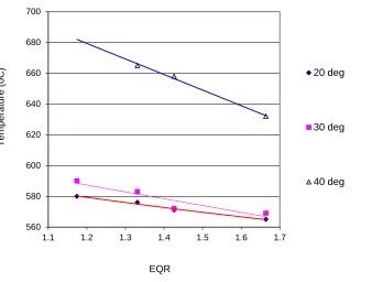
Figure 7 shows the variation of flame temperature due to the increasing of equivalent ratio (). The graph shows that the burner work on rich mixture, above the stoichiometric equivalent ratio ( >1). The highest temperature that is reached by 40o swirl-vane burner is 665 oC at of1.33. Other burner configurations, such as 30o and 20o swirl-vane burner give a lower flame temperature i.e. 590 and 580 oC at of 1.17 respectively. On these burners show a decreasing of diffusion flame when the rises to the condition of fuel rich
mixing. This causes by the reducing of reaction kinetic rate or decrease in conversion efficiency.
112304-7676 IJET-IJENS @ August 2011 IJENS I J E N S
Fig. 7. Effect of increasing the EQR- equivalent ratio () on different swirl- vane to the flame temperature
Figure 8 shows the increasing of oxygen consumption and production of carbon dioxide for the increasing of swirl-vane angle. To increase a higher flame temperature, it needs a higher air or oxygen consumption. As already explained on the previous paragraph, that the 40o swirl-vane gives a better diffusion rate, so that the oxygen reacts with the premixed fuel faster than other swirl-vane. As the consequence, the excess air at 40o swirl-vane is lower than
other swirl-vane as shown in Figure 10. It seems that the consumption of oxygen is high enough and possibly the mixing process is smoother, so that the flame temperature at 40o swirl-vane increases much higher than other swirl-vane. At = 1.66 for 20o swirl angle, the O2 consumption is 11.6 %
with the flame temperature of 565oC and with the same for 40o swirl angle, the O2 consumption is 9.1 % at 632oC.
Fig. 8. Variation of CO2 and O2 against the flame temperature on different swirl-vane angle
560 580 600 620 640 660 680 700
1.1 1.2 1.3 1.4 1.5 1.6 1.7
20 deg
30 deg
40 deg
T
e
m
p
e
ra
tu
re
(o
C)
EQR
4 6 8 10 12 14 16
550 575 600 625 650 675
CO2
O2
20 deg
30 deg 40 deg
20 deg 30 deg
40 deg
Em
is
s
io
n
o
f
CO
2
a
n
d
O
2
(%
)
112304-7676 IJET-IJENS @ August 2011 IJENS I J E N S
Other important combustion parameters are the effect increasing of to the variation of CO and NOx. Figure 9
shows the increment of CO and decreasing of NOx emission
for all swirl-vane burners on increasing from 1.16 to 1.66. The highest CO emission of 391 ppm occurs at =1.66 for 30o swirl angle, however, in average is reached 311.25 ppm for 20o swirl angle. The lowest is achieved 65 ppm at =1.33 for
40o swirl angle. The CO formation is dependence on the mixed-quality between the premixed fuel and the oxygen. As already discussed, 40o swirl angle gives a smoother diffusion between the fuel and oxygen, and encourages a higher PVC formation and RFZ structure that can increase the burning time or combustion residence time. A longer residence time produces more oxidation process to form CO2. Therefore, it
allows reducing the uncompleted reaction.
Fig. 9. Effect of the increasing of EQR- equivalent ratio () on different swirl- vane to the variation of CO and NOx emission level
Current study work in the range of equivalent ratio 1.16<<1.66 or higher than the stoichiometric value ( > 1). The graphs show that higher causes to a condition of a higher fuel composition rather than oxygen composition. As consequence, it causes a slower reaction rate and the flame temperature is not high, lower than 1000oC. Thus, this condition has an advantage to reduce the NOx formation rate.
Based on this combustion condition, the NOx forming of the
current study can be categorized in Prompt NO or Fenimore reaction mechanism. In this mechanism, NO is rapidly produced in the flame zone of laminar premixed flames long before the NO forming by the thermal mechanism. Turn [17] and Strahle [18] have described the Fenimore mechanism, that the hydrocarbon radicals are believed to react with molecular nitrogen to form amines or cyano compounds, which are then converted to intermediate compounds that ultimately form NO. In the equation form can be written as following:
CH + N2 HCN + N (a)
CH2 + N2 HCN + NH (b)
C + N2 CN + N (c)
N + O2 NO + O (d)
HCN + OH CN + H2O (e)
CN + O2 NO + CO (f)
At 30o and 40o swirl angle, the increasing from 1.16 to 1.66 does not give any significant changes of NOx reduction
of 9 and 1.14 % respectively, but for 20o swirl angle shows a significant reduction at lower of 34.92 %. The maximum NOx formation is reached of 315 ppm at = 1.16 for 20o swirl
angle and the minimum is achieved of 69 ppm at the same
0 100 200 300 400 500 600
1.1 1.2 1.3 1.4 1.5 1.6 1.7
CO NOx
20 deg
30 deg
40 deg 20 deg
30 deg
40 deg
EQR
E
m
is
s
ion
o
f
C
O
a
n
d
N
Ox
(
p
p
m
112304-7676 IJET-IJENS @ August 2011 IJENS I J E N S
for 40o swirl angle. It shows NOx reduction at smaller swirl
angle gives more significant value. A strong possibility is the combustion turbulent plays an important role. At higher swirl-vane angle, since the turbulent intensity is lower, the mixing process between air and fuel occurs is good enough to produce a high kinetic rate. For a lower swirl-vane angle, oxygen distribution is needed to control the NOx formation if it
compares with the temperature distribution as seen on Figure 7 the NOx formation shows a proportional curve distribution
with the temperature. At higher temperature, the NOx
formation is more significant. Thus, thermal NO mechanism is more significant at higher temperature.
For all swirl-vane angle, the increasing of gives the decreasing of combustion efficiency and increasing of Excess Air (EA) as shown in Figure 10. Combustion Efficiency is attributed to the degree of complete combustion of the hydrocarbon with the air mixing. Unburned hydrocarbon (UHC) is the presence of incomplete combustion, which is dominating the emission pollutant at the burner exit [13,19]
Fig. 10. Effect of the increasing the EQR- equivalent ratio () at different swirl- vane to the variation of Combustion Efficiency (CE) and Excess air
(EA) level The composition of UHC is dependence of the degree of fuel-air mixing. Increasing of EQR means that there is reducing the oxygen supply that cause a slow of reaction kinetic rate. As consequence, the EA increases and the UHC composition increases also.
The result of measurement was carried out at the exit of ax symmetric combustor over the significant range of operating conditions, i.e. the present (EQR) range. The results shows that the maximum CE reaches 95.1 % at =
1.33 for 40o swirl-vane burner. In this condition the EA reaches the lowest value of 41 %. For 30o and 20o swirl-vane burner reach the average CE of 75.82 and 73.6 % at EA of 48.75 and 89.25 % respectively. Furthermore, the variation of CE can be associated with the CO emission distribution. As happened at CO emission, the effect of aerodynamic of swirl-vane, such as increasing of swirl-vane angle from 20 to 40o, the turbulence intensity near the swirl-vane reduces. This causes a smoother diffusion between fuel and oxygen. Furthermore, it produces a better combustion process, reduces CO and UHC emission level.
4. CONCLUSIONS
Measurements and predictions of the 20o, 30o and 40o swirl-vane burner flow field and the chemistry in an air staged combustion system has been performed. The result of measurement was carried out at the exit of ax symmetric combustor over the significant range of operating conditions, i.e. the present (EQR) range. The results shows that the maximum CE reaches 95.1 % at = 1.33 for 40o swirl-vane
burner. For 30o and 20o swirl-vane burner reach the average CE of 75.82 and 73.6 % at EA of 48.75 and 89.25 % respectively. The effect of aerodynamic of swirl-vane, such as increasing of swirl-vane angle from 20 to 40o, the turbulence intensity near the swirl-vane reduces. This causes a smoother diffusion between fuel and oxygen.
ACKNOLEDGMENT
The authors are grateful to the Ministry of Science, Technology and Environment under the IRPA Research Program for research grant awarded and Combustion
40 50 60 70 80 90 100 110
1.1 1.2 1.3 1.4 1.5 1.6 1.7
112304-7676 IJET-IJENS @ August 2011 IJENS I J E N S
Laboratory Universiti Teknologi Malaysia for the support during carry out the research work.
REFERENCES
[1] Lyle, K.H., Tseng, L.K., Gore, J.P. and Laurendau, N.M. A Study of Pollutant Emission Characteristics of Patially Premixed Turbulent Jet Flames. Combustion and Flame, Vol. 116 (1999) pp. 627-639.
[2] Bradley, D., Gaskell, P.H., Gu, X.J., Lawes, M. and Scott, M.J.
Premixed Turbulent Flame Instability and NO Formation in a Lean-Burn Swirl Burner. Combustion Science and Technology, Vol. 115 (1998) pp. 515-538.
[3] Tanaka, R., Shinida, M. and Arai, N. Combustion characteristics of a heat-recirculation ceramic burner using a low-calorific-fuel.
J. of Energy Conversion and Management, vol. 42 (2001) pp. 1897-1907.
[4] Al-Shaghdari, M., Biffin, M., Froud, D. and O’Doherty, T. Validation of Turbulence Models in Swirls Burners. The Institute of Energy (1997).
[5] Gupta, A.K., Lilley, D.G., Syred, N. Swirl Flows, Abacus Press, 1984.
[6] Cheng, R.K., D. Littlejohn, P. Strakey, and T. Sidwell.. Laboratory Investigations of Low-Swirl Injectors with H2 and CH4 at Gas Turbine Conditions. Proc. Comb. Inst (2009) p.32. [7] C.K. Chan et al., Freely Propagating Open Premixed Turbulent
Flames Stabilized by Swirl, Proc. Comb. Inst, 24 (1992) p 511-518. [8] B. Bedat and R.K. Cheng, Experimental Study of Premixed Flames in Intense Isotropic Turbulence, Combustion and Flame100, no. 3 (1995) p 485-494.
[9] R.K. Cheng, Velocity and Scalar Characteristics of Premixed Turbulent Flames Stabilized By Weak Swirl, Combustion and Flame 101 (1995) no.1-2 p.1-14.
[10] Chen, R. H., and Driscoll, J. F., The Rule of the Recirculation Vortex in Improving Fuel-Air Mixing within Swirling Flames,
Twenty-Second Symposium (International) on Combustion, Combustion Institute, Pittsburgh (1988) pp. 531-440.
[11] N. Syred and J.M. Beer, Combustion in Swirling Flow: A Review, Combustion and Flame 23 (1974) p. 143-201.
[12] Shtern, V., Borrisov, A. and Hussain, F. Temperature distribution in swirling jets. Int. J. Heat Mass Transfer. Vol 41. No. 16. pp. 2455-2467. 1998
[13] Niessen,W. Combustion and Incineration Process (Applications in Environmental Engineering). Marcel Dekker. Inc. 1995.
[14] White,L.P. and Plaskett, L.G. Biomass as Fuel. Academik Press, 1981.
[15] Gupta, A.K., Lilley, D.G., Syred, N. Swirl Flows, Abacus Press, 1984.
[16] Cheng, T.S., Chao, Y,C., Wu, D.C., Hsu, H.W. and Yuan, T.
Effects of Partial Premixing on Pollutant Emissions in Swirling Methane Jet Flames. Combustion and Flame, Vol. 125, pp. 865-878 (2001).
[17] Turns, S.R. An Introduction to Combustion: Concepts and Applications. McGraw Hill Inc. 1996
[18] Strahle, W.C. An Introduction to Combustion. Gordon and Breach Science Publishers. 1993