R E S E A R C H A R T I C L E
Open Access
Flexible microscaffold facilitating the in vitro
construction of different cellular constructs
Puwanan Chumtong
1*, Masaru Kojima
1, Mitsuhiro Horade
1, Kenichi Ohara
2, Kazuto Kamiyama
1,
Yasushi Mae
1, Yoshikatsu Akiyama
3, Masayuki Yamato
3and Tatsuo Arai
1Abstract
This paper presents a flexible microscaffold to facilitate the fabrication of different cellular constructs which could be used as the building units for the construction of a larger tissue with a complex structure. The device consists of a 6×6 array of membrane actuators, made of Polydimethylsiloxane. The superiority of membrane actuators helps preventing the leakage of culture medium and allows for the formation of various temporary scaffolds. In biological test, NIH3T3 cells were seeded on the scaffold provided. The positive pressure applied to membrane actuators enables the formation of the scaffold for construction of hole array-patterned and round flat cell sheets while the negative pressure applied enables the scaffold for construction of spherical cellular aggregates. The results after 2-day cultivation show that the micropatterned cell sheet has a thickness of about 100μm and a hole diameter of about 200μm. In addition, the round flat cell sheets have a diameter of about 623.87μm, and the spherical aggregates have a diameter of about 280μm. These suggest the possibility of using our device to prepare many different cellular constructs with more complex structures in future biological applications.
Keywords: Scaffold-based approach; Microfabrication; Tissue engineering
Background
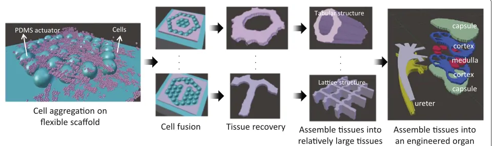
The need of engineered organs in current clinical ther-apy has been widely recognized over the past decade. Although the transplantation of healthy donated organs may reduce the death toll of such patients, the reality is that not enough persons donate organs. To solve this issue, the replacement of damaged human organ with an engi-neered organ, prepared by tissue engineering approach, has been popularly addressed since mass production of these engineered organs would certainly help to meet the high demand of transplant organs. Due to the complex-ity of an engineered organ that could mimic functions of a human organ, the fabrication by means of direct assembly, like when manufacturing a car, has caught our attention. For example, an engineered kidney could be fabricated by assembling many engineered parts such as the ureter, cap-sule, cortex, and medulla. Thus, composite tissues with different structures are necessary.
*Correspondence: [email protected]
1Graduate School of Engineering Science, Osaka University, Osaka 560-8531, Japan
Full list of author information is available at the end of the article
Generally, tissue engineering (TE) consists of 2 main approaches: cellular and acellular. Cellular approach employs small units of living cells for the construction of 3D tissues. This approach includes cell sheet stacking [1,2], cell sheet sandwiching [3], cell sheet wrapping [4,5], and 3D cell accumulation [6,7]. Tube-like and 3D thick tis-sues are mostly fabricated by such methods. However, the fabrication of tissues with more complex structures, such as toroidal, lattice, and spherical shapes, is limited without the use of a support scaffold.
In contrast, acellular approach generally employs bio-materials as a support to maintain the tissue structure during the cell fusion [8]. The use of a pre-defined mold made of biocompatible material enables the fabrication of the toroidal [9-11], lattice [12], and spherical shaped tissues [13]. However, the fixed scaffolds used in current tissue fabrication methods inherently limit the variety of tissue structures fabricated. The preparation of many indi-vidual scaffolds would consume a lot of effort and time. Furthermore, the fabrication of polymer scaffolds
shown in Figure 1. In this paper, the design and fabrication of the device will be explained. Furthermore, the appli-cability of this device in biological applications is shown by the fabrication of different cellular constructs, includ-ing micropatterned cell sheet, round flat cell sheets, and spherical aggregates.
Design methodology
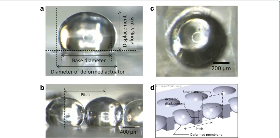
Our device consists of a 6×6 actuator array which pro-vides many temporary scaffolds as needed. As shown in Figure 2, the actuator has a base diameter of 800μm, pitch of 1100 μm, and a membrane thickness of 20 μm. The device also has a microchannel layer which allows for the flow of working fluid to each corresponding actuator. The fluid-pressure applied to the inlet enables the deformation of a membrane actuator.
Benefits of membrane actuator
Compared to other actuator types [15], the superiority of the membrane actuator made of an elastic polymer, i.e., Polydimethylsiloxane (PDMS), makes it suitable for cell cultivation because there is no gap in the actuator layer. As a result, the membrane actuator can prevent the leak-age of liquids such as culture medium. It provides a flat surface when it is not activated while it provides a partial-spherical shape when pressure is applied. When 2 adjacent actuators exhibit a large deformation, a surface contact between them is observed. The surface contacts formed by many actuators subsequently enables the formation of
its optical transparency. Moreover, the high elasticity of PDMS actuator enables the high actuator displacement [18,19]. Thus, the higher vertical displacement enables thicker micropatterned tissue to be fabricated. The elas-ticity of a PDMS membrane actuator can also be altered as needed by varying the mixing ratio [20]. The highly elasticity of PDMS makes the fully enclosed boundary provided by PDMS surface contacts possible. Further-more, the nanolayer thickness of PDMS membrane can be prepared by the addition of an extra chemical such as hexane [21,22] or toluene [23].
To form a temporary scaffold, it is inevitable that the membrane actuator exhibits a large deformation. Thus, high adhesion between PDMS membrane and the sup-port mold is necessary. The use of plastic as a supsup-port mold is not applicable due to the low adhesion between PDMS and plastic. Due to the high adhesion between PDMS parts, we hence considered a device entirely made of PDMS. Moreover, the use of an adhesive layer for the bonding [24] can also promote the adhesion between PDMS parts.
Dimension of membrane actuator
As an actuator, a very thin PDMS membrane is required, so that a small applied pressure can generate a large brane deformation, without detaching the PDMS mem-brane from the PDMS support mold. Although the higher spin coating speed results in the thinner PDMS mem-brane, there is not much thickness difference when the
a
b
c
d
Figure 2Microscopic images showing the formation of a partial spherical actuator(a), surface contact between adjacent deformed actuators(b), and top view of a cup shaped actuator(c).(d)Schematic image of an actuator array with cup shapes.
spin speed exceeds 4000 rpm [25]. For example, the spin of a mixed 10:1 (ratio of base to curing agent) PDMS at 4000 rpm for 60 s results in the membrane thickness of 20μm while the spin at 8000 rpm results in the thickness of 8μm. Furthermore, the wrinkle on PDMS membrane tends to occur easily on the thinner membrane than the thicker membrane, but the thicker membrane needs a higher applied pressure than the thinner one in order to achieve the same actuator displacement. Thus, we consid-ered a thickness of about 20μm for our design.
For the base diameter of membrane actuator, X. Arouette et al.[26] suggested that the membrane part around the base of smaller diameter-actuator is subjected to more stretching than other parts. The highly stretch can cause damage or produce wrinkle on the membrane. If wrin-kle occurs on the PDMS membrane, the membrane will not provide a flat surface again if it returns to the rest state. Moreover, during cell cultivation, the weight of cul-ture medium can easily deform such damaged membrane and cause a rough surface on the actuator layer although actuators are in the rest state. The diameter of our actua-tor is 800μm since an actuator with smaller diameter has a higher chance to have wrinkle when it exhibits a large deformation. Furthermore higher applied pressure is nec-essary for a smaller diameter actuator to achieve a high displacement. In our design, an incompressible liquid, i.e., glycerin, is used as the working fluid since it helps prevent-ing membrane deformation at rest state, due to the weight of culture medium.
Methods
Fabrication of the device
Vacuum chamber
P
c
d
e
g
PMMA
PDMS actuator mold
PDMS membrane
PDMS microchannel
Glass substrate End mill
Working fluid
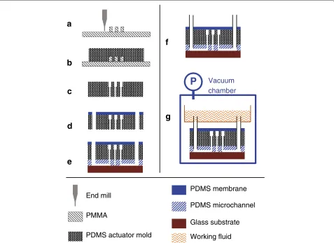
Figure 3Fabrication process of our device.(a)Micromachinning of PMMA.(b)PDMS replication of PMMA microstructures.(c)Hole punching of replicated PDMS actuator layer.(d)Coating thin PDMS membrane on the actuator layer.(e)Assembling actuator and microchannel layer. (f)Insertion of microtubes.(g)Pouring of working fluid, i.e., glycerin.
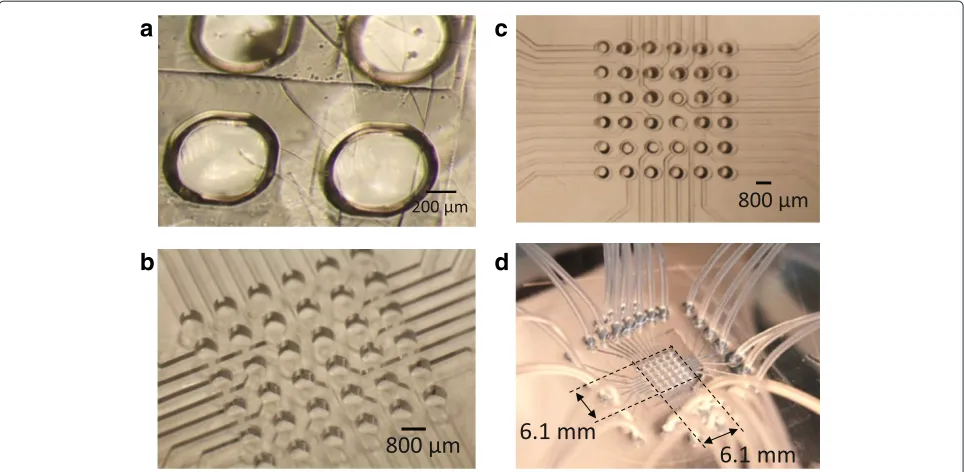
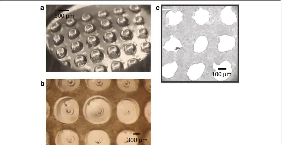
and brought into contact with a 20μm-thick PDMS mem-brane. This PDMS membrane was previously prepared by spin coating (Mikasa Co., Ltd., Japan) a 30:1 PDMS mixture at 4000 rpm for 100 s on the plain PMMA, and subsequently cured at 80°C for 20 min. The assembled part including hole-array PDMS mold and PDMS mem-brane are cured at at 80°C for 20 min, and peeled off the plain PMMA. So, the fabricated PDMS actuator layer is shown in Figure 4(a).
The preparation of PDMS microchannel or support mold is similar to that of PDMS actuator (Figure 3(a) and (b)). As shown in Figure 4(b) and 4(c), it has a channel width of 200μm and a depth of 200μm. It is made of a 20:1 PDMS mixture.
To assemble the actuator and microchannel layers, the bottom surface of actuator layer and top surface of chan-nel layer were exposed to plasma treatment using Plasma Ion Bombarder (PIB-10, Vacuum Device Inc.), and then brought into contact. The alignment of these 2 layers was
done via the observation from microscope (Figure 3(e)). As shown in Figure 4(d), the silicone tubes were inserted to the inlet ports (Figure 3(f )), and connected to a reser-voir of working fluid. The device and a reserreser-voir were degassed in a vacuum chamber over night in order to replace the air trapped inside the cavity of the microchan-nel with the working fluid (Figure 3(g)). Finally, tubes were connected with a motorized syringe used to control the deformation of membrane actuators.
Stability test using different working fluids
a
b
c
d
Figure 4Snapshots during the fabrication process including membrane actuator array(a), microchannel layer before(b)and after hole punching(c), and assembled device(d).
340μm. The motorized syringe was deactivated, and the change in the actuator displacement was observed over time.
Cell culture
Before seeding cells on the device, the actuator layer was previously coated with the 2-methacryloyloxyethyl phosphorylcholine (MPC) in order to prevent cell adhe-sion on PDMS surface. For this preparation, the device was firstly exposed to UV light in the Bio Clean Bench overnight before coating with MPC polymer. Then, Lipidure®-CM5206 (NOF Corporation, USA) was dis-solved in ethanol (Wako Pure Chemical Industries, Ltd., Japan) at 0.5 wt%. The Lipidure® solution was dropped on the actuator layer and spread consistently. Then, it was dried at room temperature for 2 hours. As a result, an adhesion reduction layer (MPC polymer) was coated on the surface of PDMS actuator layer. Then, the device was washed by Phosphate Buffer Saline (Wako Pure Chemical Industries, Ltd., Japan), submerged in Dul-becco’s modified Eagles’s Medium (Sigma-Aldrich Co., Japan) containing 10% Bovine Serum (Life Technologies™, Japan), and kept in aCO2incubator, used in cell culture,
for 3 hours.
The mouse embryonic fibroblast cells (NIH3T3) were used for the biological experiments. The 150μl of culture medium containing 5×10⁶cells of NIH3T3, which were
previously collected by centrifugation after trypsinization, were poured on the prepared scaffold.
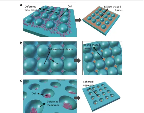
Three different cellular constructs, including micropat-terned cell sheet, round flat cell sheet, and spherical aggregate, were fabricated by our device to demonstrate the applicability in biological applications. For the fabri-cation of micropatterned cell sheet (Figure 5(a)), positive pressure was slowly applied until actuators produced a small displacement without the formation of surface con-tact. To fabricate a round flat cell sheet (Figure 5(b)), a surface contact produced by 4 adjacent actuators was cre-ated. As a result, a fully enclosed boundary was created in the middle of these actuators. Seeded cells accumulated inside this cavity, and formed into an intact tissue sheet. Since this cavity enables the formation of a cutout shaped tissue, tissues with any shapes, such as T-shape, O-shape, and L-shape, are possible to fabricate by simply changing the pattern of deformed actuators. To produce a surface contact, actuators with a diameter of 800μm should have a displacement higher than 730 μm, according the the experimental result shown in Figure 6(a). To illustrate the flexibility of our device, it can provide a structure of hole array enabling the formation of multiple spherical aggre-gates when negative pressure was applied. Seeded cells which accumulate inside holes will form into a spheroid after a period of cell cultivation.
Actuator verification Behavior of membrane actuator
b
c
Figure 5Conceptual fabrication of cell sheet with a pattern of hole array(a), round flat cell sheet(b), and multiple spherical aggregates (c)provided by a flexible scaffold.
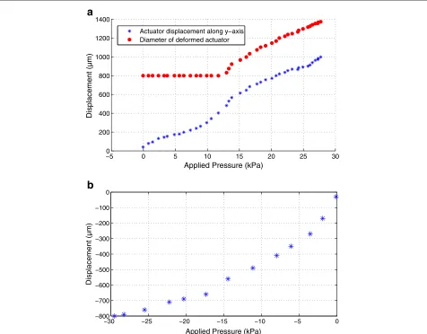
shape to a partial-spherical shape (Figure 2(a)). The base diameter which is 800 μm in our design remains unchanged while the diameter of deformed actuator and actuator displacement keep increasing as a higher pres-sure is applied. As shown in Figure 6(a), the diam-eter of deformed actuator remains at 500 μm before the applied pressure reaches over 12 kPa. When the actuator reaches a displacement along y-axis of about 730 μm, the diameter of deformed actuator is about 1100 μm. Then, the surface contact provided by adja-cent actuators (Figure 2(b)) is observed. If adjaadja-cent actu-ators are activated to achieve a higher displacement, the fully enclosed boundary is possible to fabricate. In our experiment, a cavity in the middle of 4 adjacent actuators enables the formation of a round flat cell sheet. However, if surface contact is not formed, seeded cells will form an intact cell sheet with a hole array instead.
On the other hand, when negative pressure is applied to a membrane actuator, a cup shape, enabling the construc-tion of spherical cellular aggregate, is created (Figure 2(c) and 2(d)). A higher negative-displacement is obtained when a higher decompression is applied (Figure 6(b)). In our experiment, we provided the decompression of about 30 kPa, and it produced an actuator displacement of about 800μm.
Selection of working fluid
−5 0 5 10 15 20 25 30 0
200 400 600 800 1000 1200 1400
Applied Pressure (kPa)
Displacement (
m
)
Actuator displacement along y−axis Diameter of deformed actuator
−30 −25 −20 −15 −10 −5 0
−800 −700 −600 −500 −400 −300 −200 −100 0
Applied Pressure (kPa)
Displacement (
m
)
a
b
µ
µ
Figure 6Graphs showing relation of applied positive pressure versus the geometry of partial spherical actuator(a), and relation of applied negative pressure versus the depth of cup shaped actuator(b).
membrane [29]. However, it shows that the use of liquid as working fluid slightly improves the actuator stability. On the other hand, the actuator displacement remained higher than 340 μm for more than 24 hours when glycerin, which has a much slower evaporation rate, was used. As a result, glycerin was selected for our application since the 24 hour-stability provided by glycerin is adequate for the construction of a functional tissue [7].
Results and discussion Micropatterned cell sheet
The scaffold for the construction of the micropatterned cell sheet is shown in Figure 8(a) where all actuators were activated to reach a displacement of about 600μm. Since the surface contact was not formed, cells formed into an intact cell sheet after 2 days, as shown in Figure 8(b). This cell sheet has a pattern of microhole array, and thickness
of about 100μm. After recovering cell sheet from the scaf-fold, it shrank, and its hole size became 200μm while it was 300μm before recovery.
Round flat cell sheet
0 2 4 6 8 10 12 14 16 18 20 22 24 0
50
Elasped time (hr)
Figure 7Displacement variations of PDMS actuator over time with air, DI water, and glycerin used as working fluids.
The formation of these cellular constructs were clearly observed, as shown in Figure 9(b). These constructs have an average diameter of about 623.87μm.
Spherical cellular aggregate
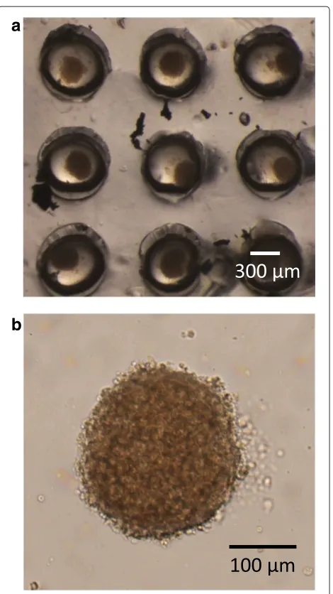
Decompression caused a membrane actuator to form a cup shape. Due to the MPC polymer coating, seeded cells did not adhere to the PMDS membrane and accumulated at the bottom of the deformed actuator. After 2 day-cultivation, cells formed a spherical aggregate, as shown in Figure 10(a). Furthermore, the array of membrane actu-ator array used in our design enables the simultaneous
fabrication of multiple spherical aggregates. The spherical aggregates have an average diameter of about 280μm. Effect of PDMS adhesion reduction
Although cells generally do not adhere to the PDMS mem-brane which is made of a 10:1 (ratio of base to the curing agent) PDMS [13], the adhesion between PDMS and cells changes when the hyperelastic PDMS membrane which has different mechanical properties is used [17]. Thus, seeded cells will not form a 3D construct, and it will be dif-ficult to recover the cellular construct from the scaffold. In our experiment, the prior coating of MPC polymer on the
a
c
b
a
b
Figure 9Microscopic images showing a scaffold with multiple enclosed boundaries(a), and the formation of round flat cell sheets on the scaffold(b).
PDMS actuators helps preventing cells from adhering to them. As a result, the fabricated cellular construct can be harvested from the device, and the device can be reused for other experiments. Before the next use, the device should be washed by PBS, exposed to UV light in bio clean bench, coated with MPC polymer, washed with PBS, sub-merged in culture medium, and kept in the incubator for about 3 hours.
In this paper, the utility of our device was confirmed by the successful fabrication of different cellular constructs. Instead of using many different fixed scaffolds, our device containing a flexible microscaffold facilitate the task by offering many different scaffolds based on the actuation patterns. The formation of cellular constructs was clearly observed via a microscope after 2 day-cultivation. The advantage of using our device is illustrated in the fabrica-tion of an intact cell sheet with a pattern of hole array. Fur-thermore the construction of round flat cell sheet suggests the superiority of using highly elastic, adhesive membrane as an actuator. Due to the coating of MPC polymer, cells aggregated and form 3D cellular constructs. Furthermore, without this coating, the recovery of fabricated cellular constructs would not be possible. In our experiment, cells
a
b
Figure 10Microscopic images showing the formation of multiple spherical aggregates on the scaffold(a), and a spherical aggregate recovered from the scaffold.
always remained their spherical shapes while they were forming their cellular interaction with each other. Fur-thermore, due to the formation of cup shape mold, cells accumulate in 3D and form into a spheroid [13]. This experiment suggests the utility of our device in the prepa-ration of different cellular constructs which could be used as building units for the construction of larger tissue with complex structures by means of part assembly, as shown in Figure 1.
Conclusions
the construction of a larger tissue will be considered.
Competing interests
The authors declare that they have no competing interests.
Authors’ contributions
CP initiated the concept, carried out the design and fabrication of the device, conducted the biological experiments, gathered and analyzed data, and drafted the manuscript. KM helped to initiate the concept, participated in the device design and biological experiments, provided facility and technical support, and helped to revise the manuscript. HM participated in the design and fabrication of the device, provided facility and technical support, and helped to revise the manuscript. OK, KK, MY, AY, and YM participated in the design and fabrication of the device, gave technical advises, and helped to revise the manuscript. AT helped to initiate the concept, participated in the device design, provided all support and advises, and helped to revise the manuscript. All authors read and approved the final manuscript.
Acknowledgments
This work was supported in part by Grant-in-Aid for Scientific Research on Innovative Areas "Bio Assembler" (23106005), and by "Nanotechnology Platform Project (Nanotechnology Open Facilities in Osaka University)" from the Ministry of Education, Culture, Sports, Science and Technology of Japan [F-13-OS-0005, S-13-OS-0004].
Author details
1Graduate School of Engineering Science, Osaka University, Osaka 560-8531,
Japan.2Faculty of Science and Technology, Meijo University, Aichi 468-8502, Japan.3Institute of Advanced Biomedical Engineering and Science at TWIns, Tokyo Women’s Medical University, Tokyo 162-8666, Japan.
Received: 8 May 2014 Accepted: 30 June 2014
References
1. Shimizu T, Yamato M, Kikuchi A, Okano T (2003) Cell sheet engineering for myocardial tissue reconstruction. Biomaterials 24(13):2309–2316 2. Haraguchi Y, Shimizu T, Sasagawa T, Sekine H, Sakaguchi K, Kikuchi T,
Sekine W, Sekiya S, Yamato M, Umezu M, Okano T (2012) Fabrication of functional three-dimensional tissues by stacking cell sheets in vitro. Nat Protocols 7(5):850–858
3. Sugibayashi K, Kumashiro Y, Shimizu T, Kobayashi J, Okano T (2013) A molded hyaluronic acid gel as a micro-template for blood capillaries. J Biomater Sci Polym Ed 24(2):135–147
4. Kubo H, Shimizu T, Yamato M, Fujimoto T, Okano T (2007) Creation of myocardial tubes using cardiomyocyte sheets and an in vitro cell sheet-wrapping device. Biomaterials 28:3508–3516
5. Masuda T, Yamagishi Y, Takei N, Owaki H, Matsusaki M, Akashi M, Arai F (2013) Three-dimensional assembly of multilayered tissues using water transfer printing. J Robot Mechatronics 25(4):690–697
6. Kachouie NN, Du Y, Bae H, Khabiry M, Ahari AF, Zamanian B, Fukuda J, Khademhosseini A (2011) Directed assembly of cell-laden hydrogels for engineering functional tissues. Organogenesis 6(4):234–244
7. Nishiguchi A, Yoshida H, Matsusaki M, Akashi M (2011) Rapid construction of three-dimensional multilayered tissues with endothelial tube networks by the cell-accumulation technique. Adv Mater 23:3506–3510
8. Tsang VL, Bhatia SN (2004) Three-dimensional tissue fabrication. Adv Drug Delivery Rev 56:1635–1647
Three-dimensional cell culture device utilizing thin membrane deformation by decompression. Sensor Actuat B-Chem 147:376–379 14. Ma PX (2004) Scaffolds for tissue fabrication. Materialstoday 7(5):30–40 15. Volder MD, Reynaerts D (2010) Pneumatic and hydraulic microactuators: a
review. J Micromech Microeng 20(4). doi:10.1088/0960-1317/20/4/043001. 16. Chumtong P, Kojima M, Ohara K, Horade M, Mae Y, Akiyama Y, Yamato M, Arai T (10–13 November 2013) An Active Microscaffold for Applications in Tissue Engineering In: international Symposium on
Micro-NanoMechatronics and Human Science. Institute of Electrical and Electronics Engineers, Nagoya, Japan
17. Ryoo JH, Jeong GS, Kang E, Lee SH (2–6 October 2011) Ultrathin, hyperelastic PDMS nano membrane: fabrication and characterization. In: the 15th international conference on miniaturized systems for chemistry and life sciences. Royal Society of Chemistry, Seattle, Washington, USA
18. Kwon HJ, Lee SW, Lee SS (2009) Braille dot display module with a PDMS membrane driven by a thermopneumatic actuator. Sensors Actuat A-Phys 154(2):238–246
19. Watanabe J, Ishikawa H, Arouette X, Matsumoto Y, Miki N (2012) Demonstration of vibrational braille code display using large displacement micro-electro-mechanical systems actuators. Jpn J Appl Phys:51. doi:10.1143/JJAP.51.06FL11.
20. Khanafer K, Duprey A, Schlicht M, Berguer R (2009) Effects of strain rate, mixing ratio, and stress-strain definition on the mechanical behavior of the polydimethylsiloxane (PDMS) material as related to its biological applications. Biomed Microdevices 11(2):503–508
21. Sang S, Witte H (2010) Fabrication of a surface stress-based PDMS micro-membrane biosensor. Microsystem Technol 16(6):1001–1008 22. Thangawng AL, Ruoff RS, Swartz MA, Glucksberg MR (2007) An ultra-thin
PDMS membrane as a bio/micro-nano interface: fabrication and characterization. Biomed Microdevices 9(4):587–595
23. Wu H, Huang B, Zare RN (2005) Construction of microfluidic chips using polydimethylsiloxane for adhesive bonding. R Soc Chem 5:1393–1398 24. Eddings MA, Johnson MA, Gale B (2008) Determining the optimal
PDMS-PDMS bonding technique for microfluidic devices. J Micromech Microeng:18. doi:10.1088/0960-1317/18/6/067001.
25. Zhang WY, Ferguson GS, Talic-Lucic S (25–29 January 2004) Elastomer-supported cold welding for room temperature wafer-level bonding In: the 17th IEEE international conference on micro electro mechanical systems. Institute of Electrical and Electronics Engineers, Maastrichit, Netherlands 26. Aroutte X, Matsumoto Y, Ninomiya T, Okayama Y, Miki N (2010) Dynamic
characteristics of a hydraulic amplification mechanism for large displacement actuators systems. Sensors 10:2946–2956
27. Merkel TC, Bondar VI, Nagai K, Freeman BD, Pinnau I (2000) Gas sorption, diffusion, and permeation in poly(dimethylsiloxane). J Polym Sci Part B 38:415–434
28. Johnson M, Liddiard G, Eddings M, Gale B (2009) Bubble inclusion and removal using PDMS membrane-based gas permeation for applications in pumping, valving and mixing in microfluidic devices. J Micromech Microeng 19(9). doi:10.1088/0960-1317/19/9/095011.
29. Zhang Y, Ishida M, Kazoe Y, Sato Y, Miki N (2009) Water-vapor permeability control of PDMS by the dispersion of collagen powder. IEEJ T Electr Electr 4(3):442–449
doi:10.1186/s40648-014-0009-4
Cite this article as:Chumtonget al.:Flexible microscaffold facilitating the
in vitro construction of different cellular constructs.ROBOMECH Journal