(UDC: 539.183.3:519.673)
Finite element elastic analysis of hypar shells on winkler foundation
R. J. Aziz1, A. A. Al-Azzawi2 and Ali A. Al-Ani3
1Nahrian University, Baghdad, Iraq riyadh1948@yahoo.com
2Nahrian University, Baghdad, Iraq dr_adel_azzawi@yahoo.com 3Baghdad University, Baghdad, Iraq ali1972@yahoo.com
Abstract
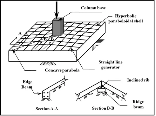
In this research, the hyperbolic paraboloidal shell is investigated. The two components of the interacting system; the soil and the shell foundation, are modelled using the finite element method. In this study, 9-node isoparametric degenerated shell element with five degrees of freedom at each node was used. The soil-structure interaction between the shell elements and the supporting medium are model in this study by representing the soil medium by certain analytical equivalent such as Winkler model with both normal compressional and tangential frictional resistances.
A parametric studies have been carried out to investigate the effect of some important parameters on the behaviour of shell foundations. These parameters are: shell thickness, shell warp, ridge and edge beams cross-sectional dimensions.
Comparison between the results obtained by the present analysis and those obtained by many other investigations are made. The present analysis shows satisfactory results when compared with those obtained by other studies with largest percentage difference of 4.4097 % in the value of the vertical displacement value.
Key words: Elastic analysis, finite element, hypar shell, Winkler foundation.
1.Introduction
considered for use as foundation is the pyramidal combination of four inclined trapezoidal plate elements, that can support a column at its centre. Since these pyramidal folded plates can be rendered square or rectangular in plan, they can be combined to form multiple units to serve as combined footings. The construction is simpler as hypar footing. The pyramid shell foundation can be modeled by flat shell finite elements.
Fig. 1. Individual hypar footing.
The literature pertaining to the theoretical studies on the behavior of shell foundations is reviewed herein.
Bairagi and Buragohain, (1985) have applied the finite element technique to study the stress analysis of a square hypar footing under axial and moment loads. In that study, various three dimensional isoparametric finite elements have been used to model the shell and the soil half space.
Melerski, (1986) presented an approximate elastic solution to the statical problem of a reinforced concrete shell foundation, the method of analysis being based on the finite difference procedure in the variational formulation.
Kurian, (1993) investigated the performance of shell foundations on soft soils. Two types of shell foundations have been used, which were the hypar and the conical shell foundations. The soil was represented by Winkler springs, in which the subgrade reaction (kn) of the soil is varied to simulate a wide range of soil conditions.
Kurian, (1994) studied the behavior of shell foundations under subsidence of core soil. This problem has been addressed in respect of shell foundations in a single cone, a double cone and a hyperbolic paraboloid. These systems were analyzed by the finite element method.
Al-Azzawi, (2000) studied the nonlinearity in material and geometry by using the finite element method for the analysis of reinforced concrete shell foundations under static loading. The response of reinforced concrete shell foundation was traced through its elastic, inelastic and ultimate load ranges. He also used a layered approach in his analysis by dividing the concrete into eight layers. Also, a number of steel reinforcement layers were smeared into the concrete layers at appropriate position. The shell was modeled by using nine-node curved shell element.
Hassan, (2002) investigated the behavior of hypar and conical shells on Winkler foundations. The two components of the interaction system; the soil and the foundation, were modeled using the finite element method. Four-node elements with six and five degrees of freedom per node were used in the analysis.
2. Finite element method
The Ahmad-type degeneratedisoparametric shell elements based on independent rotational and translational displacement interpolation have become popular in recent years. In this element, the Mindlin-type theory is employed. The normal to the middle surface of the three-dimensional element is constrained to remain straight after deformation in order to overcome the numerical difficulty associated with the large stiffness ratio in the through-thickness direction. Also, this element neglects the strain energy associated with stresses perpendicular to the local x'y'
surface and constrains the normal stress component to zero to simplify the constitutive equations. By adopting the isoparametric geometric description, the element can be used to represent thin and thick shells with arbitrary shapes, circumventing the complexities of classical shell theory and differential geometry (Ahmad et al. 1970).
The four coordinate systems used in the degenerated shell element formulations are shown in Fig. 2.
(1) Global Cartesian coordinate system (x, y, z or xi). (2) Natural coordinate system (,,).
(3) Local Cartesian coordinate system (
x
',
y
',
z
'or
x
'i). (4) Nodal Cartesian coordinate system ( k3 k 2 k 1,V ,V
Fig. 2. Coordinate systems for the degenerated shell element.
3. Elastic foundation
For a foundation represented by Winkler model for both compressional and frictional resistances, the stiffness matrix is given by Al-Azzawi (1995):
n n w w w f]
[R
..
0
0
..
..
..
..
0
..
]
[R
0
0
..
0
]
[R
K
(1)
f5 f4 f3 f2 f1 wK
0
0
0
0
0
K
0
0
0
0
0
K
0
0
0
0
0
K
0
0
0
0
0
K
R
(2)The stiffness of foundation is distributed on the nodes of the element like the distribution of pressure load on the bottom surface of the element ( = 1), thus at node k
1 1 1 1 k xf1 k N (ξ, η) J(ξ, η,ζ) dξ dη
K ' (3)
1 1 1 1 k yf2 k N (ξ, η)J(ξ, η,ζ) dξ dη
K ' (4)
1 1 1 1 k zf3 k N (ξ, η)J(ξ, η,ζ) dξ dη
K ' (5)
1 1 1 1 k k s xf4 k h2 N (ξ, η) J(ξ, η,ζ) dξ dη
K ' (6)
1 1 1 1 k k s yf5 k h2 N (ξ, η)J(ξ, η,ζ)dξ dη
K '
(7)
where
k
x',
k
y'and
k
z' are the subgrade reaction coefficients in the local coordinates ks ' '
' ,y and z, h
x is the thickness of the shell at node k, Nk(ξ, η) is the shape function at node k and
J(
ξ
,
η
,
ζ
)
is the determinant of the Jacobian matrix.4. Applications and discussions
In this paper, an example have been analyzed by a computer program named SFAP (Shell Foundation Analysis Program), (Al-Azzawi 2000) which is developed from a program named PLAST (Huang 1989) by adding subroutines of foundation properties and stiffnesses in order to be capable of solving different types of shell foundations.
4.1 Hyperbolic paraboloidal shell foundation
Melerski (1986)analyzed a square hypar shell foundation by the finite difference method. The square hypar footing has 5m × 5m in plan with 0.5m rise and 0.1m thickness. The edge and ridge beams cross sectional dimensions are 0.2m × 0.3m and the footing is subjected to a central vertical load of 1600kN. The elastic properties of the hypar shell are (E = 24 × 106kN/m2 and
The problem is solved by the finite element method and due to symmetry one quadrant of the shell is taken for the analysis. Due to symmetry, one quadrant of footing is analyzed by using 9-node isoparametric degenerated shell elements as shown in Fig. 3. This problem was also solved by Hassan (2002) who used a different finite element model. In the present study, the results are compared with both Melerski (1986) and Hassan (2002). Figure 4 shows the variation of the vertical displacement along the diagonal of the footings. Figures 5 and 6 show the variation of axial force and the bending moment in the edge beam, respectively. Figures 7 and 8 show the variation of axial force and bending moment in ridge beam, respectively.
The percentage difference in results (for the vertical displacement) between the present study and Melerski (1986)is about 4.409 %. The percentage difference in results between the present study and Hassan (2002)is about 7.083 %.
Fig. 4. Variation of vertical displacement along the diagonal of hypar shell.
Fig. 5. Variation of axial force in ridge beam.
Fig. 7. Variation of axial force in edge beam.
Fig. 8. Variation of bending moment in edge beam.
4.2 Parametric study
In order to study the influence of variation of selected parameters on the behavior of the hypar shell foundations, four parameters are considered which are: shell warp, shell thickness, ridge beam cross sectional dimensions and edge beam cross sectional dimensions.
4.2.1 Shell warp
The influence of variation of shell warp (k f ab) on its behavior is now considered. Different values are taken (k = 0.08, 0.16, 0.24, 0.32, 0.4m-1). Figure 9 shows the variation of the vertical displacement along the diagonal. From this figure, it is seen that with increasing the shell warp, the vertical displacement decreases near and at the center of the hypar shell while it increases when it approaches the edges. This behavior is due to the increase in the concentrated load component towards the edges of the shell with the increase in the shell warp.
the ridge beam. Figure 12 shows that the variation of the axial force in the ridge beam decreases. From this figure, it is seen that the axial force decreases with the increase in the shell warp which is due to reason that the increase in the shell warp will cause a decrease in the membrane shearing stress in the shell.
4.2.2 Shell thickness
The influence of variation of shell thickness is now considered. Five values of shell thickness were considered in this study (h = 0.1, 0.15, 0.2, 0.25 and 0.3m). Figure 13 shows the variation of the vertical displacement along the diagonal of the hypar footing. From this figure it is found that the vertical displacement decreases at the center of the footing (i.e. under the concentrated load) and increases near the edges. This behavior is the result of increasing the shell rigidity, i.e. the hypar shell tries to reduce the vertical displacement.
Figures 14 and 15 show the variation in the bending moment and the shearing force in the ridge beams, respectively. It is seen that the bending moments and the shearing forces decreases with the increase in the shell thickness which is due to the decrease in the variation of the vertical displacement. Figure 16 shows the variation of the axial force in the ridge beam. From this figure it is seen that the axial force decreases with the increase in the shell thickness. 4.2.3 Ridge beam cross sectional dimensions
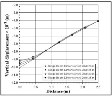
Four values of ridge beam cross sectional dimensions are taken (0.20m × 0.20m, 0.20m × 0.25m, 0.20m × 0.30m and 0.20m × 0.35m). Figure 17 shows the variation of the vertical displacement along the ridge beam. It is seen that with increasing the cross sectional dimensions of the ridge beam, the vertical displacement at the center of the hypar shell will decrease. This behavior is due to the four ridge beams meeting at the center of the hypar shell and they will increase the hypar shell stiffness and so to decrease the vertical displacement at the same position.
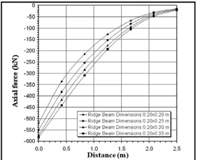
Figures 18, 19 and 20 show the variation of the bending moment, shear force and axial force in the ridge beam, respectively. The values of the bending moment, shearing force and axial force in the ridge beam will increases with increasing its cross sectional dimensions. This behavior is due to the fact that the ridge beam stiffness is increased and will attract more forces. 4.2.4Edge beam cross sectional dimensions
Four values of edge beam cross sectional dimensions are taken (0.20m × 0.20m, 0.20m × 0.25m, 0.20m × 0.30m and 0.20m × 0.35m). Figure 21 shows the variation of the vertical displacement along the edge beam. It is seen that with increasing the cross sectional dimensions of the edge beam, the vertical displacement at the center of the beams will decrease while it will increase near edges. This behavior is due to the increase in the edge beam rigidity by increasing its cross sectional dimensions.
Fig. 9. Effect of variation of shell warp on the vertical displacement along the diagonal.
Fig. 10. Effect of variation of shell warp on the bending moment in ridge beam.
Fig. 12. Effect of variation of shell warp on the axial force in ridge beam.
Fig. 13. Effect of variation of shell thickness on the vertical displacement along thediagonal.
Fig. 15. Effect of variation of shell thickness on the shear force in ridge beam.
Fig. 16. Effect of variation of shell thickness on the axial force in ridge beam
Fig. 18. Effect of variation of ridge beam cross sectional dimensions on the bending moment in ridge beam.
Fig. 19. Effect of variation of ridge beam cross sectional dimensions on the shear force in ridge beam.
Fig. 21. Effect of variation of edge beam cross sectional dimensions on the vertical displacement along edge beam.
Fig. 23. Effect of variation of edge beam cross sectional dimensions on the shear force in edge beam.
Fig..24. Effect of variation of edge beam cross sectional dimensions on the axial force in edge beam.
5. Conclusions
The major conclusions obtained from the study of the hypar shell foundation are: 1. Increasing the shell warp from 0.08m-1 to 0.16m-1.
decreases the vertical displacement by about (31.5 %) near and at the center of the hypar shell while it increases by about (70.11 %) when it approaches the edges.
decreases the bending moments in the ridge beams by about (53.53 %).
decreases the shearing forces in the ridge beams by about (24.94 %).
decreases the vertical displacement by about (5.2 %) at the center of the hypar shell while it increases by about (10.78 %) when it approaches the edges.
decreases the bending moments in the ridge beams by about (21.22 %).
decreases the shearing forces in the ridge beams by about (15.97 %).
decreases the axial force in the ridge beams by about (20.48 %).
3. Increasing edge beam cross sectional dimensions from 0.2m 0.2m to 0.2m 0.25m.
decreases the vertical displacement by about (1.25 %) at the center of the edge beams while it increases about (19.53 %) when it approaches the edges.
increasing the bending moments in the edge beams by about (41.46 %).
increasing the axial forces in the edge beams by about (11.43 %).
increasing the shearing forces by about (29.59 %) at the center of edge beams while it decreases by about (23.60 %) at the ends of those beams.
4. Increasing ridge beam cross sectional dimensions from 0.2m 0.2m to 0.2m 0.25m.
decreases the vertical displacement by about (2.95 %) at the center of the hypar shell foundation.
increasing the bending moments in the ridge beams by about (41.42 %).
increasing the shearing forces in the ridge beams by about (23.53 %).
increasing the axial forces in the ridge beams by about (6.06 %).
Извод
Еластична
анализа
коначним
елементима
х
y
пар
(
хипербполично
параболоидне
)
љуске
на
Винклеровој
подлози
R. J. Aziz1 , A. A. Al-Azzawi2 and Ali A. Al-Ani3
1Nahrian University, Baghdad, Iraq riyadh1948@yahoo.com
2Nahrian University, Baghdad, Iraq dr_adel_azzawi@yahoo.com 3Baghdad University, Baghdad, Iraq ali1972@yahoo.com
Резиме
Уовомраду, проучаванајехиперболичнапараболоиднаљуска. Двекомпонентесистема интеракције, тло и подлоге од љуске су моделиране користећи методу коначних елемената. У овој студији је коришћен деветоцворни изопараметарски дегенерисани елемент љуске са пет степена слободе у сваком чвору. Интеракција тло-структура измедјуелеменатаљускеипотпорногслојајемоделованауовојстудијипредстављањем слоја тла одређеним аналитичким еквивалентима као што су Винклеров модел са нормалнимкомпресивнимитангецијалнимфрикционалнимотпорима.
Изведене су параметарске студије како би се истражио утицај неких важних параметара на понашање подлоге од љуске. Ти параметри су: дебљина љуске,
витоперењељускеидимензијегреднихпресекаивица.
Извршенасу поређења резултата добијенихсадашњом анализом ионих добијених многим другим истраживањима. Садашња анализа показује задовљавајуће резултате
када се пореде са онима који су добијени другим студијама, са највецим процентом разликеод 4.4097 % увредностимавертикалнихпомерања.
Клучнеречи: Еластичнаанализа, коначниелементи, хyпарљуска, Wинклероваподлога
References
Ahmad S., Irons B. M. and Zienkiewicz O. C. (1970). Analysis of Thick and Thin Shell Structures by Curved Finite Elements, International Journal for Numerical Methods in Engineering, 2, 419-451.
Al-Ani A. A. (2006).Finite Element Elastic Analysis of Shells on Winkler Foundations, M.Sc. Thesis, Faculty of Engineering, Nahrain University, Baghdad, Iraq.
Al-Azzawi A. A. (1995).Thick Circular Plates on Elastic Foundations. M.Sc. Thesis, Faculty of Engineering, Nahrain University, Baghdad, Iraq.
Bairagi N. K. and Buragohain D.N. (1985). Application of Finite Element to Hypar Shell Footings. Proceedings of the 2nd International Conference on Computer Aided Analysis and Design in Civil Engineering, Roorkee, III, 61-69.
Hassan S. A. (2002). Finite Element Analysis of Shell Footings. M.Sc. Thesis, College of Engineering, Al-Mustansiria University, Baghdad, Iraq.
Huang H. C. (1989). Static and Dynamic Analysis of Plates and Shells, Springer-Verlag, London, UK.
Kurian N. P. (1982). Modern Foundations: Introduction to Advanced Techniques. Tata-MacGraw Hill, New Delhi.
Kurian N. P. (1993). Performance of Shell Foundation on Soft Soil. Proceedings of the International Conference on Soft Soil Engineering, Guangzhou, November, 383-392. Kurian N. P. (1994). Behavior of Shell Foundations under Subsidence of Core Soil. Proceedings
XIII of the International Conference on Soil Mechanics and Foundation Engineering, New Delhi, Jan., 2, 591-594.
Kurian N. P. (1995). Parametric Studies on the Behavior of Conical Shell Foundations. Proceedings V East Asia-Pacific Conference on Structural Engineering and Construction, Gold Coast, Australia, July, II, 1733-1738.