PHOTONIC STRUCTURES AND DEVICES MOLDED ON SOFT POLYMER MATERIALS
Cary Aaron Tippets
A dissertation submitted to the faculty of the University of North Carolina at Chapel Hill in partial fulfillment of the requirements for the degree of Doctor of Philosophy in the Department of Applied
Physical Sciences in the College of Arts and Sciences.
Chapel Hill 2017 Approved by: Rene Lopez Edward Samulski Michael Falvo Daphne Klosta Sergei Sheiko
ii ©2017 Cary Aaron Tippets ALL RIGHTS RESERVED
iii ABSTRACT
Cary Aaron Tippets: Biomimetic Structures and Shape Active Polymers (Under the direction of Rene Lopez)
Polymer materials are ubiquitous, relatively cheap, easy to process, and functionalize, making them interesting for many applications, in particular for optical systems that are
traditionally fabricated from rigid and expensive materials. Polymer properties can be exploited to modulate the optical response of photonic structures. In this dissertation, I will discuss the fabrication and demonstration of several applications of soft polymers in the field of optics. Soft polymers can be used to fabricate structures with optical effects inaccessible using a single optical element created from standard materials. First, I employed a biomimetic approach to produce structural color similar to the bright blue of the Morpho Butterfly. Second, I used shape active polymers to reversibly modulate the height of an optical grating through heat. Lastly, I developed a varifocal polymer lens for an augmented reality system.
Structural Color, as opposed to pigmented color, is the result of light interacting with structures with geometrical length scales comparable with the wavelength of visible light. There are many examples of structural color found in nature, from the various colors of the jewel beetles to the vibrant blue of the kingfisher bird. This structural effect can typically be identified by the iridescent nature of the coloration. I will discuss my approach toward biomimicry of the unique photonic structure found on the surface of the Morpho butterfly wings. This sub-micron sized structure is a ridge which in cross-sectional view resembles a tree, with a thin “trunk” and
iv
many periodic “branches” that produce a multilayer interference effect, strongly reflecting a brilliant blue color over a wide angular range.
Biomimicry of the Morpho butterfly nanostructure has been attempted but the angular insensitivity has never been fully shown in a man-made replica. I will discuss the importance of the inherent randomness found within the Morpho structures that causes light to spread over such a large range. Here in, I will show two different fabrication approaches to integrate microstructure randomness and the consequence of such variations on the angular response. In structures that were fabricated using interference lithography a quasi-randomness (incomplete randomization) is induced through drying. Angular measurements show that a two-lobe reflection, much alike that produced by the true butterfly wing, is produced in angular space and is attributable to this quasi-random nanostructure. However, periodicity needs to be fully destroyed in order to overcome diffraction. To do this a direct-write lithography system was built and used to produce completely non-periodic structures. The results showed a more pronounced a two-lobe reflection at oblique angles. Finite-difference time-domain (FDTD) simulations were employed to understand this reflection signature and to determine effect of other geometric features. From these simulations a photonic structure, capable of spreading light in similar fashion to the butterfly, and that can be fabricated with standard microfabrication techniques is proposed.
In connection to the use of polymers in diffractive structures, I will discuss my work with shape active polymers. Shape memory polymers offer a unique approach for application that demand multipurpose parts and have been utilized as heart stents and actuators. The applicability of these shape memory polymers as optical elements is demonstrated by examining the optical response of a shape shifting diffraction grating. As the height of the diffraction grating is
v
reversibly changed the intensity of diffracted light is modulated. This constitutes a simple device realization that nevertheless illustrates the materials and optical issues that arise from the
application of shape memory polymer in more complex photonic shapes will lead to the optical systems with versatile components.
Finally, the use of elastomeric polymers as shape active lens will be explored. Varifocal lenses have shown the potential to solve an inherent problem in virtual and augmented reality headsets. In augmented and virtual reality headsets, the human eye will focus on the screen several inches from the face but images for both eyes are off set in order cause the users eyes to converge at a certain angle, imitating distance. In the real-world focus and vergence are in sync but these headsets encounter what is known as vergence–accommodation conflict and it is the source of major user discomfort. Vergence–accommodation conflict prevents the wide spread adoption of these potentially impactful technologies. I will present my work in developing a varifocal half silvered mirror for use in an augmented reality system. The system was validated by a perception test that showed users having increased success when the system was properly focused
vi
To Carla, Thanks for walking to the end of the road with me. Now let’s play some games.
vii
ACKNOWLEDGEMENTS
I would like to thank Rene, who has honestly been the best advisor I could have asked for. You allowed me to grow and figure many things out on my own and put up with me telling you on multiple occasion that I had figured out the problem, only to then find another.
I would like to thank my committee namely Edward Samulski, Michael Falvo, Michael Rubinstein, Daphne Klosta, Sergei Sheiko for the advice you offered over the years. I would not be the scientist I am without all the many people that I collaborated with throughout my PhD. Thank you to Qaioxi Li and David Dunn for introducing me to interesting problems, materials and applications. Thanks to my polymer chemist friends, Sarah Brosnan, Sara Turner, Annie Jackson and Kate Houston for letting me ask constant questions about polymers and synthesizing polymers for me.
My education would not have been the same without guidance and input from our group postdocs Eugene Donev and Yulan Fu. Your friendship and mentorship is greatly valued and appreciated. Thanks to Yinchi Lui for teaching me about OPVs. Thanks to Qian Dong, Taylor Moot, Tim Garvey and Robert Call, you always offered helpful advice that propeled my work forward and your friendship kept me sane. Taylor thanks for brainstorming with me, our crazy side projects were often my favorite to pursue.
I have had the opportunity to work with serval outstanding undergraduate students during my time here and have enjoyed getting to know each of them. I am most grateful to Adam Kunesh, who embraced the butterfly project and was able to get the direct write lithography
viii
system up and running. Your ability to focus a laser still amazes me. You are a fantastic scientist and I wish you the best in your graduate work.
Finally, I would like to thank my family, without your support I would have never made it through this crazy endeavor. To my parents who literally never let a week pass without telling me “the only good PhD is a done PhD”, for 6 years…Thanks for the encouragement and you were right the whole time. To my children who deprived me of sleep but lit up every single day for me, helping me to keep life in perspective. And to my wife, Carla, you are my rock and my favorite person. Thanks for supporting me and helping me to stay the course.
ix
TABLE OF CONTENTS
List of Figures ... xiii
List of Abbreviations and Symbols... xv
Chapter 1 Introduction ... 1
1.1 Introduction ... 1
1.2 Biomimicry: Structural color and taking inspiration from nature ... 2
1.2.1 Structural Color in Nature ... 3
1.2.2 Structural color of the Morpho Butterflies ... 6
1.2.3 Physics of the structural color of the Morpho butterfly ... 7
1.2.4 Optical Properties of the Morpho butterfly: double angle measurement ... 8
1.3 The Shape Memory Effect ... 10
1.3.1 Shape Memory Polymers ... 11
1.3.2 Reversible Shape Memory Polymers ... 12
1.3.3 Length Scales: From Macro to Micro to Nano ... 13
1.4 Augmented Reality ... 14
1.4.1 Vergence and Accommodation in the Eye ... 14
1.4.2 Vergence-Accommodation conflict in AR and VR ... 15
References ... 17
Chapter 2 Biomimetic Photonic Structures and their Angular Reflection ... 21
2.1 Introduction ... 21
2.2 Possible Applications of Biomimetic Butterfly Structures ... 21
2.3 Review of Bioinspired butterfly structures ... 22
2.4 Experimental Methods ... 23
2.4.1 PFPE synthesis ... 23
2.4.2 Fabrication of hard master ... 24
2.4.3 Interference Lithography and development ... 25
2.4.4 Fabrication of PFPE structures ... 28
2.4.5 θ-ϕ measurements ... 29
2.4.6 Normal-incidence reflection measurements ... 30
x
2.5 Results and Discussion ... 31
2.5.1 Morpho Butterfly θ-ϕ measurements ... 31
2.5.2 Biomimetic Periodic Nanostructure ... 33
2.5.3 Quasi-periodic nanostructures ... 35
2.5.3.1 Randomness via drying ... 36
2.5.3.2 Optical Results of Quasi periodic nanostructures ... 37
2.5.3.3 Importance of Absorption ... 38
2.5.4 Origin of the Optical Signature ... 39
2.5.4 FDTD Simulations ... 40
2.6 Conclusion ... 43
References ... 45
Chapter 3 Controlled Randomness through Direct Write Lithography and Surface Modification ... 48
3.1 Introduction ... 48
3.2 Previous attempts to randomize ... 49
3.3 Maskless Lithography ... 49
3.4 Experimental methods ... 50
3.4.1 Direct write lithography with nano stepper control ... 50
3.4.2 Chemical vapor deposition of multilayers ... 51
3.4.3 Fabrication of hard master ... 52
3.5 Results and Discussion ... 53
3.5.1 Disrupting the periodicity ... 53
3.5.2 Uniform random distribution ... 54
3.5.3 Normal random Distribution ... 56
3.5.4 Addition of Chopper ... 57
3.5.5 FDTD Simulations: controlling the angular spread ... 58
3.5.5.1 Effects of branch asymmetry ... 58
3.5.5.2 Effects of branch shape ... 60
3.5.5.3 Effect of trunk size ... 61
4.5.5.4 Effect of branch taper ... 62
3.5 Conclusion ... 63
References ... 65
xi
4.1 Introduction ... 67
4.2 Introduction to Soft Lithography and Optical Applications... 67
4.2.1 Shape Active Optics via Soft Lithography ... 68
4.3 Experimental Methods ... 69
4.3.1 Materials ... 69
4.3.2 Synthesis of PFPE ... 70
4.3.2 Fabrication of PFPE Soft Masters ... 70
4.3.3 Fabrication of SMP gratings ... 70
5.3.4 Atomic Force Microscopy and Height Analysis ... 71
4.3.5 Optical measurement ... 72
4.4 Results and Discussion ... 73
4.4.1 POA Operational Temperature Range ... 73
4.4.2 Bulk Reversibility ... 75
4.4.3 Theoretical Diffractive Intensity ... 76
4.4.4 Optical Reversibility ... 77
4.4.5 Polymer Crystallization ... 80
4.4.6 Recovery of Intensity... 81
4.4.6 Separating scattering and diffraction ... 81
4.4.7 Repeatability and Fatigue ... 83
4.4.8 Physical reversibility ... 84
4.4.9 Discrepancy between physical and optical reversibility... 85
4.5 Conclusion ... 86
References ... 88
Chapter 5 Dynamic Optical Lens for Augmented Reality ... 90
5.1 Introduction ... 90
5.2 Review of approaches to overcoming limitations in NEDs ... 91
5.3 Experimental methods ... 91
5.3.1 Optical Design ... 91
5.3.2 Membrane requirements and materials ... 92
5.3.3 Fabrication of membrane ... 93
5.3.5 Housing Design ... 94
xii
5.4 Results and Discussion ... 95
5.4.1 Implementation ... 95
5.4.2 Effects of pre-stretching membrane ... 96
5.4.3 Wavelength dependent reflection ... 98
5.4.4 Loss of resolution due to focal depth ... 99
5.4.5 Membrane durability ... 99
5.4.6 Perception test results ... 101
5.5 Conclusion ... 104 References ... 106 Chapter 6 Conclusion ... 108 6.1 Thesis Contribution ... 108 6.2 Looking Forward ... 109 6.2.1 Biomimetic Structures ... 109
6.2.2 Shape active gratings ... 109
6.2.3 Varifocal membranes mirror ... 110
6.2.4 Moon Shot ... 110
xiii
LIST OF FIGURES
Figure 1.1 Sources of structural color. ... 3
Figure 1.2 Reversible color change in the skin of a male panther chameleon ... 4
Figure 1.3 The blue tarantula and its nanostructure ... 5
Figure 1.4 Images of Morpho rhetenor butterfly ... 6
Figure 1.5 Scanning electron micrographs of Morpho rhetenor scales ... 7
Figure 1.6 Morpho nanostructure schematic ... 8
Figure 1.7 Angular reflection of a Morpho wing. ... 10
Figure 1.8 Shape memory Programing process ... 12
Figure 1.9 Vergence and Accommodation ... 15
Figure 1.10 Real world and near eye display vergence and accommodation ... 16
Figure 2.1 Hard Master Fabrication ... 25
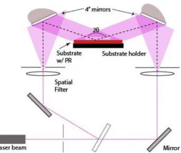
Figure 2.2 Interference lithography set up ... 26
Figure 2.3 Polymer replica process for Morpho-inspired ultrastructures ... 28
Figure 2.4 The θ-ϕ experimental setup. ... 29
Figure 2.5 Experimental and simulated θ-ϕ of the Morpho rhetenor ... 32
Figure 2.6 SEM of periodic nanostructures. ... 33
Figure 2.3. SEM micrographs of qausi-periodic structures ... 36
Figure 2.9 Optical analysis of quasi-periodic sample ... 37
Figure 2.10 Underlying order ... 40
Figure 2.11 FDTD simulations ... 42
Figure 3.1 Direct Write Lithography System ... 51
Figure 3.2 Direct write fabrication flow ... 52
Figure 3.3 SEM aerial and cross-section micrographs ... 54
Figure 3.4 Double angle measurements for various uniform distribution periodicities ... 55
Figure 3.5 FDTD simulation of a multilayer stake with and without a “trunk” ... 56
Figure 3.6 Normal distribution θ-ϕ graphs. ... 57
Figure 3.7 Uniform distributions with chopper. ... 58
Figure 3.8 FDTD simulations comparing the effect of offset branches ... 59
Figure 3.9 Simulation of original biomimetic structure and determination of the effect of branch shape ... 60
Figure 3.10 FDTD simulation exploring the effect of trunk shape and thickness ... 62
xiv
Figure 4.1 Chemical Structure of Poly(octylene adipate) ... 69
Figure 4.2 The SMP molding process... 70
Figure 4.3 Average ridge height calculation ... 72
Figure 4.4 Optical measurement set up... 73
Figure 4.5 A differential scanning calorimetry (DSC) thermogram of a crosslinked POA ... 74
Figure 4.6 A dogbone bulk sample’s maximum reversibility was characterized by DMA tensile test ... 75
Figure 5.8 Theoretical expectation of the experimental results. ... 76
Figure 4.9 Optical modulation of a reversible SMP grating ... 78
Figure 4.10 The diffraction and scattering intensity change with temperatures ... 80
Figure 5.11 Optical measurements of a permanent grating, with no programed secondary memory ... 83
Figure 4.12 AFM images of as prepared and at room temperature grating ... 85
Figure 4.13 evidence of plastic deformation... 86
Figure 5.1 A sketch showing the varifocal optical layout ... 92
Figure 5.2 Membrane fabrication process ... 94
Figure 5.3 AR Implementation ... 95
Figure 5.4 A view approximating the point spread function across the membrane ... 96
Figure 5.5 Black and white grid projection on to the membrane as the focal depth is changed .. 97
Figure 5.6 Reflectance and Transmission of coated membrane ... 99
Figure 5.7 Photographs showing the result of the deformation test ... 100
Figure 5.8 Series of photographs showing example stimulus... 102
Figure 5.9 Perception test ... 103
Figure A1 Full Simulation branch shape ... 112
Figure A2 Full FDTD simulations comparing the effect of offset branches ... 113
Figure A3 Full FDTD simulation exploring the effect of trunk shape and thickness ... 114
xv
LIST OF ABBREVIATIONS AND SYMBOLS
1D 1 dimensional
2D 2 dimensional
3D 3 dimensional
AFM Atomic force microscopy
AR augmented reality
CVD chemical vapor deposition DMA Dynamic mechanical analysis DSC Differential Scanning Calorimetry Ebeam electron beam lithography
FDTD finite difference time domain
FOV field of view
NED near eye display
LPCVD low pressure chemical vapor deposition
IL Interference lithography
M. rhetenor Morpho rhetenor
Nm nanometer
PDMS Polydimethylsiloxane
PET Polyethylene terephthalate
PECVD plasma enhanced chemical vapor deposition PFPE perfluoropolyether
POA polyoctylene adipate
RSM reversible shape memory
SEM scanning electron microscope
SMP Shape memory polymer
Tm melting temperature
Tp Partial melting temperature
xvi
VR virtual reality
θ Incident angle
ϕ reflected or scattered angle
δ height of grating
1
Chapter 1 Introduction 1.1 Introduction
Polymers have already found their way into a multitude of technological areas and have the potential to increase the functionality of a great variety of components. Soft polymers in particular could add useful functionality to optical systems by allowing control of the optical response. Standard optical elements are typically crafted from hard materials, while these faithfully serve a single purpose, multi-functional polymer optics that could provide cheap, replicable, and on demand photonic structures. I will discuss the application of soft polymers in order to access or enhance an optical response, and how this can be used in widely different areas (or for different purposes). The first part of this dissertation focuses on structural colors inspired by the Morpho butterfly wing structure. I will review various photonic biological models found in nature, in terms of their unique nanostructures that are the sources of their remarkably brilliant colors. In particular, I will discuss the Morpho rhetenor butterfly. Secondly, I will present a brief discussion on shape memory effects in materials, with particular emphasis in the shape memory effect that arises from polymers. Shape memory polymers offer a simple manner by which to manipulate photonic shapes, thus controlling the optical response.
2
Finally, I will discuss a fundamental limitation in current augmented reality headsets, which produces a mismatch in the human visual system. This limitation, along with several others, can be address by the use of elastomeric polymer lenses Therefore, in the following sections of this introductory chapter, I address the background of each of the components of this three-pronged dissertation on applications of soft polymers in optical structures.
1.2 Biomimicry: Structural color and taking inspiration from nature
Biomimicry is the process by which methods and designs from nature are replicated or used as inspiration to solve complex real world problems. Scientist often seek to replicate the natural model and then improve upon it. Classic examples of biomimicry, such as the supposed story of how the Wright brother took inspiration from pigeons to develop their flight machine [1] or more recently on the development of Velcro, which was inspired by the surface of burrs [2], illustrate the impact biomimicry can have on the innovative process. A peculiar occurrence in nature is that of structural color, displayed on a variety of animals and plant spices, it is characteristically vibrant and exhibits several other unique optical attributes. These optical properties could be exploited and make it an attractive target for biomimicry. However, it should be noted that biomimicry of these optical properties requires that the structures responsible for these phenomena be crafted from a material, or materials, with a single refractive index (or a system that can be approximated as such). Fabricating such structures from hard materials has been done using natural templates, but soft polymers provide the opportunity to use different fabrication routes, while satisfying the optical requirements.
3
1.2.1 Structural Color in Nature
Scientists fascination with structural color reaches back to the inception of the study of optics, when Robert Hooke and Sir Isaac Newton studied the coloration of the peacock feather and observed that the reflected light is” tinged… in a most curious manner”. [3,4] Within the last several decades scientists have become increasingly interested in understanding and explaining the source of structural color exhibited by different animals, insects and plants.[5–8] Structural color in nature can often be identified by a strong metallic or iridescent appearance. Structural color, as opposed to pigmented color, is the result of nanostructures found on the biological surface, which interfere with the incident light and reflects only a specific limited range of electromagnetic wavelengths. The simplest example of structural color is thin film interference, when an incident light is reflected by each boundary of the film. The thickness of the thin film will dictate the wavelength of light that undergoes constructive interference when reflected. This in effect gives the perception of color when light is incident on the film. Everyday examples of this can be seen on the surface of a bubble or oil spreading out over the surface of water.
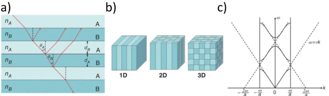
Figure 1.1 Sources of structural color. A multilayer structure, with alternating layers of high and low index materials (a). Reflects a preferential wavelength depending on the layer thickness and incident angle. (b) shows 1D ,2D, and 3D crystalline structures that produce photonic effects.(c) Band dispersion diagram of a 1D photonic crystal.[8]
4
All structural color found in nature, can be simplified down to a multilayer or crystalline structure with dimensions on the scale of the visible wavelength of light. Shown in Figure 2.1a, when light impinges on a multilayer photonic stack of periodic layers that alternate between materials of high and low refractive indices, only certain wavelengths will undergo constructive interference, when reflected. Reflected wavelengths can be controlled by thickness of these alternating layers and the respective refractive indices. For multilayer stacks the apparent color will change as the observation angle changes, producing the iridescent property. Likewise, with any photonic crystal, from a 1 dimensional (1D) multilayer to a two-dimensional (2D) or three-dimensional (3D) spatially periodic photonic crystal, similar physics can be observed. 2D and 3D photonic structures optical behavior is comparable to crystalline solids. The contrasting periodic refractive indices give rise to a photonic band gap in similar fashion that crystalline solids give rise to an electronic band gap though the lattice arrangement of ions.
Examples of structural colors due to multilayer reflection can be found on beetles[9–11], birds[12], tarantulas[13] and butterflies[5,14], as well as other animals[15–17]. While multilayer reflection is the most common source of structural color in nature, there are many examples of structural colors due to a 3D crystalline structure.[18] For example, the chameleon’s color
a)
c)
b)
Figure 1.2 Reversible color change in the skin of a male panther chameleon from relaxed to excited state (a). (b) TEM images of the lattice of guanine nanocrystals in S-iridophores from the same individual in a relaxed (left panel) and excited (right panel) state. Scale bar, 200 nm. (c) Reflectivity of a chameleon skin sample with white skin osmolarity from 236 to 1416 mOsm.[19]
5
changing ability was recently shown to be the result of crystal structures in its skin, shown in Figure 1.2. When the chameleon feels threatened or aroused the nanostructured layer of skin will contract, changing the spacing between the nanoparticles and thus the color reflected.[19]
Additionally the chameleon has a deeper skin layer that is embedded with rod-like nanoparticles that reflects infrared light, aiding the reptile in staying cool.[19]
The underlying mechanism of structural color found in nature can be understood with simple physical principles however, the structures themselves vary in complexity As the
photonic structures increase in complexity, the optical response acquires unique characteristics. [13,20,21] Take for example the blue tarantula, shown in Figure 1.3, the ultrastructure consists of multilayers wrapping around the hair, combined with sub cylindrical multilayers intertwined with the underlying multilayers. This complexity results in a nearly non-iridescent color while still maintaining short and long range order.[22] Another fascinating example of structural color is that of the Morpho butterfly genus. The optical behavior of the Morpho butterfly genus has piqued the interest of researchers due to its high intensity, color purity, and unique angular response. The Morpho butterflies color is the results of a distinct nanostructure on the surface of their wings.
Figure 1.3 The blue tarantula and its nanostructure. Shown in (a) the Ischnocolinae tarantula. (b) and (c) show SEM and TEM micrographs of the spiders nanostructure. [13]
6
1.2.2 Structural color of the Morpho Butterflies
Although the colors and patterns of the different Morpho subspecies differ, the
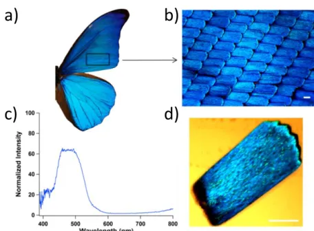
underlying nanostructures are quite similar. From the bluish white of the M. sulkowskyi to the dull blue of the M. peleides, each butterfly has ridges with tree like structures on the surface of the scales on their wings.[23] In particular, the M. rhetenor subspecies is known for its amazing blue color, shown in Figure 1.4(a–d). The thousands of overlapping scales combine to reflect over 60% of incident blue light. Over the last several decades M. rhetenor has been studied in detail, and the source of its optical behavior is now well understood.[24–27]
Figure 1.4 Images of Morpho rhetenor butterfly show the various structures found on its wings. a) A photograph of one half of the butterfly. b) Optical micrograph of the wing’s tilted scales. c) An individual scale with grating-like structures visible. d) Reflection spectrum of the Morpho
wing, with an intensity peak between 460 and 500 nm. Scale bars: 50 μm
a)
c)
b)
7
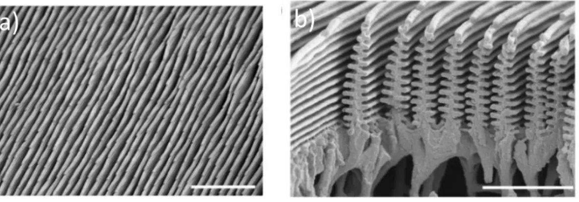
Figure 1.5 Scanning electron micrographs of Morpho rhetenor scales. (a) Quasi-parallel rows with varying heights and periods. b) The cross-section of the Morpho ultrastructures, showing alternating lamellae. Scale bars: a) 5 μm, b) 2 μm
1.2.3 Physics of the structural color of the Morpho butterfly
The nanostructures responsible for this brilliant color are quasi periodic ridges (Figure 1.5a) whose cross-sections resemble pine trees made of chitin (Figure 1.5a). A schematic of the nanostructure is shown in Figure 1.6, with each of the optically relevant geometrical parameters labeled. The “pine-tree” branches (lamellae) on either side of each tree are vertically offset (a), thus producing an asymmetric structure. Each pine-tree ridge randomly varies in height (h) and lateral spacing from its neighbors (b). A well as a tree “trunk” that has a slight taper (t). This hierarchical arrangement is often referred to as an “ultrastructure”. The alternating lamellae-and-air stack of the ultrastructure gives rise to a multilayer interference effect, which regulates the wavelength of reflected light.[5,21,25,28–30] The spacing between each lamellae (d) dicatate that the structure will relfect blue light and the index of the chitin will determine the effective intesity of the reflection. Chitin has an index of refraction of 1.55, producing a large contrast between the lamellae and the air. The color purity across a wide range of viewing angles is enabled by the quasi-periodicity of the structures, which causes the light to spread.[23]
8
Diffraction effects are smeared out due to irregularity in the height of the ultrastructures and the asymmetry of each individual tree.[28,31,32]The irregularity of the structures thus allows each ridge to contribute separately to the overall optical effect.
Figure 1.6 Morpho nanostructure schematic. There are several important geometrical parameters that are responsible for the unique optical response of the Morpho butterfly. The irregular
spacing between ridges (b), and variation in height (h) along each ridge eliminate diffraction. The multilayer lamellae- air stack preferentially reflects the blue wavelengths based on the distance between lamellae (d). The “trunk” taper and asymmetric offset of the branches on each side of the ridges, give rise to the characteristic two lobe reflection. This unique reflection is best characterized by looking at the angle of reflections ϕ for each incident angle θ.
1.2.4 Optical Properties of the Morpho butterfly: double angle measurement
The M. rhetenor’s ability to spread light is difficult to visualize when observing the butterfly. Yoshioka and Kinoshita, presented the angular spread of light from various Morpho subspecies, by placing a single wing/scale in front of reflective paper with a small hole for the incident light to come through.[26] Shown in Figure 1.7, the M. rhetenor’s reflection is compared to the M.
didus, here it can be clearly seen just how effectively the butterfly nanostructures are able to
spread the reflective light over a wide angular range. Additionally, Figure 1.7 demonstrates the
ϕ
θ
h
d
a
b
t
9
angular insensitivity of the reflected wavelengths. Careful inspection of the photographs would reveal a high intensity lobe all around the hole used to let incident light pass, with very little light being specularly reflected. However, this effect is hard to quantify in this simple experiment. Kambe et al. showed that measuring the incident angle (θ) vs scattering angle (ϕ) can provide an informative physical description of the angular color response.[33] M. rhetenor has been shown to actually exhibit a two-lobe back reflection in angular space. The θ - ϕ measurement will be explored in further detail in section 2.4.5 and description of the M. rhetenor’s angular reflection will be discussed in section 2.5.1.
10
1.3 The Shape Memory Effect
The shape memory effect, is often associated with a class of so called ‘smart’ materials that have the potential to find applications across a whole swath of industries, from aerospace, to
a)
b)
c)
Figure 1.7 Angular reflection of a Morpho wing. (a) M. rhetnor (b) M. didius (c) experimental set up [26]
11
biomedical and optics. Shape memory materials are those that have the ability to ‘memorize’ a certain permanent shape (macroscopic or microscopic) and be fixed into a secondary (temporary) shape through an applied external stimulus. This process can then be reversed through the
application of the same stimulus, thus the material ‘remembers’ the original shape. Shape memory optics could be particularly attractive application for these materials. A single optical element capable of multiple photonic shapes, would dramatically increase the functionality without increasing complexity of a given system. One of the first reports of the shape memory effect came in 1941, from L.B Vernon who claimed his methacrylic acid ester resin had an ‘elastic memory’, for dental applications.[34,35] The most advanced applications of the shape memory effect come from the use of shape memory alloys, which typically occur in materials with two stable crystalline structure. Each crystalline structure is thermodynamically favorable at different temperature and a transition can be observed through the application of heat. AuCd was the first reported shape memory alloy in 1951, but since then researchers have discovered a plethora of materials that exhibit this effect. Draw backs of shape memory alloys include non-tunable transition temperature, high cost, high stiffness and limited recoverable strain (~8%).[35] These limitations gave the proper motivation for researches to develop alternative materials. Polymers provided the pathway to overcome many of the limitations of shape memory alloys, namely cost, and the ability to tune stiffness, recoverable strain and transition temperature.
1.3.1 Shape Memory Polymers
Shape Memory Polymers (SMPs) are a group of polymers that have the ability to switch between one or more programed shapes. Research into SMPs, began to gain steam in the 1980’s and has quickly advanced, with SMPs finding their way into applications including stents, self-folding structures, and smart clothing.[36,37] SMP and composites have been shown to
12
responsive to external stimulus of heat, sound, light, and electricity.[38–41] By far the most common type of SMPs are semi crystalline polymers that can transition between shapes via heat. These SMPs, as illustrated in Figure 1.8, are first crossed-linked (physically or covalently) into a permanent (primary) shape. Once cross linked, the polymer can be heated above the crystallite melting temperature (Tm) and molded, stretched or compressed into a secondary shape. The
polymer is then quickly quenched, which freezes the crystallites into a secondary shape. When desired, the SMP can be heated above its Tm and it will revert to its original permeant shape.
SMPs have been used in several applications were a single programing event is viable, such as stents.[37] However, a major limitation to SMPs is that without application of external
constraints most shape memory processes are irreversible.[42–44] In most applications, a reversible processes would be needed for SMP products to be utilized as an optical element.
Figure 1.8 Shape memory Programing process
1.3.2 Reversible Shape Memory Polymers
Reversible shape memory (RSM), in which the shape can be actively tuned, was recently reported and shown to be able to reliably switch between its permeant and secondary
13
shape.[40,45,46] These processes require no external forces and do not need to undergo
reprograming in between actuation. This hands-free functionality is the results of the interaction between the crosslinked polymer chains and the crystalline scaffold. When the polymer is heated to any temperature below its melting point (Tm), a crystalline scaffold remains. The crystalline
scaffold provides a latent crystalline template, and the programmed shape is recovered upon cooling due to self-seeded crystallization along kinetically preferred pathways to replicate the scaffold. This reversibility can be controlled by tuning the chemical crosslinking density and the partial melting temperature. For poly(octylene adipate) bulk reversibility as high as 75% has been reported.[45]
1.3.3 Length Scales: From Macro to Micro to Nano
Almost all reported results of SMP actuation are on the scale of > 1 mm. Within the last decade micron and sub-micron SMP have been reported.[47–50] Zhao et al., showed the formation of micron and submicron wrinkles on the surface of pre-deformed SMP substrate coated with a thin gold film. After heating, the substrates returned to their primary shapes which induced sub-micron wrinkling. They were able to control the pattern and size of wrinkling depending on how the process of setting the secondary shape. RSM sub micron features were reported by Turner et al., they were able to show the change in contact angle as the height of different sub-micron shapes were varied.[51] SMPs have shown adequate ability to work on micron and sub-micron lengths scales but the optical response of RSM structures have not been studied. An RSM optical grating is an initial step in validating RSM polymers as suitable materials for truly multifunctional SMP optical elements.
14
1.4 Augmented Reality
Augmented reality (AR) is the overlaying of computer-generated images onto the real world in real time. In contrast, virtual reality (VR) is a completely immersive technology that closes off the user from the surrounding world and all images are computer-generated. Augmented reality has the potential to impact every industry and academic field, from
engineering to computer science, architecture and the arts. The user base could be unlimited. However, in order to fully take advantage of the vast potential of augmented reality, there are several fundamental limitations in near eye displays (NED) used for AR and VR that need to be overcome. These limitation include limited field of view, low angular resolution and fixed accommodation.[52] Typically addressing just one of these limitations requires tradeoff in the others. Interchanging elastomeric polymer lenses in place of the traditional glass lenses, used in these systems, is one approach to improve on all of these limitations.
1.4.1 Vergence and Accommodation in the Eye
In order to understand the limitations of current NED it is important to review how the human eye focuses at varying distances. When the human eye attempts to focus on a near object, the lens of the eye will bend to bring into focus the light from the object. Likewise, when light comes from an object at a further distance, the eye lens must again bend to bring the object into focus. This process is called accommodation and is shown in Figure 1.9. Before accommodation can occur, the human eyes must rotate inward to converge so that the images coming from both eyes overlap, this process is called vergence. When objects are at a far distance the eyes will be parallel, as the distance between the eyes is small compared to the distance of the object. Likewise, when the object is close the eyes must rotate acutely until the images converge. An example of vergence is shown in Figure 1.9.
15
1.4.2 Vergence-Accommodation conflict in AR and VR
Vergence and accommodation happen nearly instantaneously, and go relatively unnoticed during in everyday life. However, in basic AR and VR systems the content display is positioned approximately three inches from the viewer’s eye. This presents a conflict between vergence and accommodation, as the lens of the eye will be focused on the light coming from the screen. Yet the eyes will converge on an object at any distance in the given field of view. This is often referenced as vergence-accommodation conflict and is the source of major discomfort for AR users. An example of viewing real world objects and NEDs, is shown in Figure 1.10. One way that companies and researchers have tried to address this issue, is by placing a single lens in between the user and the screen. At a focal length of 1 to 2m, as light coming from this distance tends to provide the most comfort possible over all distances. However, the need to fully address this issue remains, before wide spread adoption of this technology is possible. Elastomeric polymers allow for a new approach to overcoming this frustrating limitation. Elastomeric lenses
Accommodation
Convergence
Cornea Near Object Near Object Far Object Far Object16
would provide on demand accommodative cues, possibly eliminating VAC in AR systems all together.
V
er
ge
nce Di
st
ance
Foc
al Di
st
ance
V
er
ge
nce Di
st
ance
Foc
al Di
st
ance
Near Eye Display
Real World
Display Screen
Figure 1.10 Real world and near eye display vergence and accommodation. With a real world object the vergence and focal distances are the same. In a near eye display system, the vergence and focal distance differ, causing visual discomfort for the user.
17
REFERENCES
[1] Howard F 1988 Wilbur and Orville: A Biography of the Wright Brothers (New York: Ballantine Books)
[2] Suddath C 2110 A Brief History of: Velcro Time
[3] Hooke R 1665 Micrographia, xxxvi. Of Peacoks, Ducks, and other Feathers of
changeable colours. (London)
[4] Newton I 1704 Opticks (William Innys at the West-End of St. Paul’s, London)
[5] Kinoshita S and Yoshioka S 2005 Structural colors in nature: the role of regularity and irregularity in the structure. Chemphyschem 6 1442–59
[6] Vukusic P 2011 Structural colour: elusive iridescence strategies brought to light. Curr.
Biol. 21 R187-9
[7] Parker A R 2000 515 Million Years of Structural Colour J. Opt. A Pure Appl. Opt. 2 R15–28
[8] Fu Y, Tippets C A, Donev E U and Lopez R 2016 Structural colors: from natural to artificial systems Wiley Interdiscip. Rev. Nanomedicine Nanobiotechnology 8 758–75 [9] Schenk F, Wilts B D and Stavenga D G 2013 The Japanese jewel beetle: a painter’s
challenge. Bioinspir. Biomim. 8 45002
[10] Anderson T F and Richards A G 1942 An Electron Microscope Study of Some Structural Colors of Insects J. Appl. Phys. 13 748–58
[11] Durrer H and Villiger W 1972 Schillerfarben von Euchroma gigantea (L.): (Coleoptera: Buprestidae): Elektronenmikroskopische untersuchung der elytra Int. J. Insect Morphol.
Embryol. 1 233–40
[12] Stavenga D G, Leertouwer H L, Marshall N J and Osorio D 2011 Dramatic colour changes in a bird of paradise caused by uniquely structured breast feather barbules. Proc.
Biol. Sci. 278 2098–104
[13] Hsiung B-K, Deheyn D D, Shawkey M D and Blackledge T A 2015 Blue reflectance in tarantulas is evolutionarily conserved despite nanostructural diversity Sci. Adv. 1
e1500709–e1500709
[14] Ghiradella H 1991 Light and color on the wing: structural colors in butterflies and moths.
Appl. Opt. 30 3492–500
[15] Search H, Journals C, Contact A, Iopscience M, Appl P and Address I P 2000 515 million years of structural colour 15
[16] Fu Y, Tippets C A, Donev E U and Lopez R 2016 Structural colors: from natural to artificial systems Wiley Interdiscip. Rev. Nanomedicine Nanobiotechnology n/a-n/a [17] McPhedran R C and Parker A R 2015 Biomimetics: Lessons on optics from nature’s
18
[18] Simonis P and Vigneron J P 2011 Structural color produced by a three-dimensional photonic polycrystal in the scales of a longhorn beetle: Pseudomyagrus waterhousei (Coleoptera: Cerambicidae) Phys. Rev. E 83 11908
[19] Teyssier J, Saenko S V., van der Marel D and Milinkovitch M C 2015 Photonic crystals cause active colour change in chameleons Nat. Commun. 6 6368
[20] Caveney S 1971 Cuticle Reflectivity and Optical Activity in Scarab Beetles: The Role of Uric Acid Proc. R. Soc. London. Ser. B. Biol. Sci. 178205 LP-225
[21] Smith G S 2009 Structural color of Morpho butterflies Am. J. Phys. 77 1010
[22] Hsiung B-K, Deheyn D D, Shawkey M D and Blackledge T A 2015 Blue reflectance in tarantulas is evolutionarily conserved despite nanostructural diversity Sci. Adv. 1
e1500709–e1500709
[23] Kinoshita S, Yoshioka S and Miyazaki J 2008 Physics of structural colors Reports Prog.
Phys. 71 76401
[24] Vukusic P and Sambles J R 2003 Photonic structures in biology. Nature 424 852–5 [25] Zhu D, Kinoshita S, Cai D and Cole J 2009 Investigation of structural colors in Morpho
butterflies using the nonstandard-finite-difference time-domain method: Effects of alternately stacked shelves and ridge density Phys. Rev. E 80 51924
[26] Yoshioka S and Kinoshita S 2004 Wavelength-selective and anisotropic light-diffusing scale on the wing of the Morpho butterfly. Proc. Biol. Sci. 271 581–7
[27] Lee R T and Smith G S 2009 Detailed electromagnetic simulation for the structural color of butterfly wings. Appl. Opt. 48 4177–90
[28] Siddique R H, Diewald S, Leuthold J and Hölscher H 2013 Theoretical and experimental analysis of the structural pattern responsible for the iridescence of Morpho butterflies Opt.
Express 21 14351–61
[29] Steindorfer M a, Schmidt V, Belegratis M, Stadlober B and Krenn J R 2012 Detailed simulation of structural color generation inspired by the Morpho butterfly. Opt. Express
20 21485–94
[30] Banerjee S, Cole J B and Yatagai T 2007 Colour characterization of a Morpho butterfly wing-scale using a high accuracy nonstandard finite-difference time-domain method.
Micron 38 97–103
[31] Kinoshita S, Yoshioka S and Kawagoe K 2002 Mechanisms of structural colour in the Morpho butterfly: cooperation of regularity and irregularity in an iridescent scale. Proc.
Biol. Sci. 269 1417–21
[32] Johansen V E 2014 Optical role of randomness for structured surfaces. Appl. Opt. 53 2405–15
[33] Kambe M, Zhu D and Kinoshita S 2011 Origin of retroreflection from a wing of the morpho butterfly J. Phys. Soc. Japan 80 1–10
19
[34] Vernon L B and Vernon H M 1941 Producing Molded Articles such as Dentures from Thermoplastic Synthetic Resins US Pat. 2234993
[35] Liu C, Qin H and Mather P T 2007 Review of progress in shape-memory polymers J.
Mater. Chem. 17 1543
[36] Ratna D and Karger-Kocsis J 2008 Recent advances in shape memory polymers and composites: A review J. Mater. Sci. 43 254–69
[37] Yakacki C M, Shandas R, Lanning C, Rech B, Eckstein A and Gall K 2007 Unconstrained recovery characterization of shape-memory polymer networks for cardiovascular applications Biomaterials 28 2255–63
[38] Havens E, Snyder E a. and Tong T H 2005 Light-activated shape memory SPIE 5762,
Smart Structures and Materials 2005: Industrial and Commercial Applications of Smart Structures Technologies vol 5762, ed E V. White pp 48–55
[39] Xie T 2010 Tunable polymer multi-shape memory effect. Nature 464 267–70
[40] Behl M, Razzaq M Y and Lendlein A 2010 Multifunctional shape-memory polymers.
Adv. Mater. 22 3388–410
[41] Liu Y, Lv H, Lan X, Leng J and Du S 2009 Review of electro-active shape-memory polymer composite Compos. Sci. Technol. 69 2064–8
[42] Chung T, Romo-Uribe A and Mather P T 2008 Two-way reversible shape memory in a semicrystalline network Macromolecules 41 184–92
[43] Pandini S, Passera S, Messori M, Paderni K, Toselli M, Gianoncelli A, Bontempi E and Ricc T 2012 Two-way reversible shape memory behaviour of crosslinked poly(??-caprolactone) Polymer (Guildf). 53 1915–24
[44] Westbrook K K, Mather P T, Parakh V, Dunn M L, Ge Q, Lee B M and Qi H J 2011 Two-way reversible shape memory effects in a free-standing polymer composite Smart
Mater. Struct. 20 65010
[45] Zhou J, Turner S A, Brosnan S M, Li Q, Carrillo J Y, Nykypanchuk D, Gang O, Ashby V S, Dobrynin A V and Sheiko S S 2014 Shapeshifting: Reversible Shape Memory in Semicrystalline Elastomers ⊥
[46] Meng Y, Jiang J and Anthamatten M 2015 Shape actuation via internal stress-induced crystallization of dual-cure networks ACS Macro Lett. 4 115–8
[47] Altebaeumer T, Gotsmann B, Pozidis H, Knoll A and Duerig U 2008 Nanoscale shape-memory function in highly cross-linked polymers Nano Lett. 8 4398–403
[48] Bae W G, Choi J H and Suh K Y 2013 Pitch-tunable size reduction patterning with a temperature-memory polymer Small 9 193–8
[49] Wang Z, Hansen C, Ge Q, Maruf S H, Ahn D U, Qi H J and Ding Y 2011 Programmable, pattern-memorizing polymer surface Adv. Mater. 23 3669–73
20
[50] Zhao Y, Huang W M and Fu Y Q 2011 Formation of micro/nano-scale wrinkling patterns atop shape memory polymers J. Micromechanics Microengineering 21 67007
[51] Turner S a, Zhou J, Sheiko S S and Ashby V S 2014 Switchable Micropatterned Surface Topographies Mediated by Reversible Shape Memory. ACS Appl. Mater. Interfaces [52] Kruijff E, Swan J E and Feiner S 2010 Perceptual issues in augmented reality revisited
21
Chapter 2
Biomimetic Photonic Structures and their Angular Reflection
2.1 Introduction
Several optical characteristics of the M. rhetenor make it an attractive model to understand and emulate. The reflected color is nearly angular independent, until viewed at oblique angles and the nanostructure has a large specific surface area that is open to the
environment, making it very sensitive to the surrounding medium. In this chapter I will discuss my initial approach to fabricating biomimetic Morpho nanostructures and the introduction of randomness through controlled drying. As will be shown, the introduction of randomness is crucial to begin to approach the optical qualities of the butterfly wings.
2.2 Possible Applications of Biomimetic Butterfly Structures
Artificial photonic structures inspired by the Morpho butterfly could exploit its unique optical properties for a variety of applications[1,2]Morpho-mimetic and simplified
22
temperature sensors.[7,8]Further advances may allow for tunable structural color to find application in high precision- and broad-color gamut displays, waveguides, non-duplicable security labels and camouflage technology. In order for these applications to possess similar optical sensitivity, Morpho-inspired nanostructures must retain the Morpho butterfly’s optical and morphological features.
2.3 Review of Bioinspired butterfly structures
The complex shape of the Morpho nanostructure is a challenge for any potential fabrication. Alternative approaches to produce structural color include rigid and polymeric multilayers[9,10]or self-assembled colloidal films.[11–13] While these methods can produce non-diffractive colors observable near normal incidence, intense diffractive colors with strong angular dependence are observed outside of this narrow angular range. Angle dependence in the reflection spectra of multilayer stacks and colloidal films has been overcome by applying lessons from the Morpho butterfly, utilizing variations in height and periodicity to produce structural randomization.[14–16]However, multilayer stacks fail to reproduce the large specific surface area and angular response of the butterfly, limiting the possible applications, such as sensors that require a large surface area to elicit a wavelength response while interacting with gases or liquids.
Attempting to replicate the exact structure of the butterfly, some researchers have used the butterfly wings as a biological template for direct molding.[7,17–21]This approach
accurately reproduces the exact shape of the ultrastructure and the optical response can be tuned by changing the composition or thickness of a deposited coating on top of the butterfly
structures.However, the need for the natural template limits the applicability of any such device. Ultrastructures that exhibit optical effects similar to the butterfly’s optical response have been
23
demonstrated by direct ion beam writing[22]and e-beam lithography,[5,23,24]but these methods are limited in scale and avoid the diffraction effects of periodic structures by studying the optics of a few structures. Recently Zhang et al. showed a new approach to fabricating Morpho-like biomimetic structures by the use of ebeam lithography. Zhang used a multilayer stack of polymethyl methacrylate and Lift-Off resist, after ebeam exposure the multilayers were dissolved via alternating development of the layers. Siddique et al. demonstrated a photolithography
method that allows for large-area fabrication and broad angular response for blue light, but the fabrication method does not allow for the introduction of randomness similar to the butterfly to break the periodicity.[25]
I will show the fabrication and optical characterization of periodic and quasi-periodic ultrastructures made of perfluropolyether (PFPE). The polymer material allows for the
introduction of randomness, in order to optically decouple the individual ridges. Both periodic and quasi-periodic versions of the artificial butterfly structures differ substantially in their angular response but have similar normal-reflection spectra, which peak in the region of the real butterfly’s color.
2.4 Experimental Methods 2.4.1 PFPE synthesis
1g (1 mmol) perfluoropolyether (PFPE) (Solvay Solexis) was dissolved in 50 mL dry methylene chloride. Triethylamine (2 mmol, 0.2 g) was dropwise added to the solution at 0 °C. 2-Isocyanatoethyl methacrylate (2.1 mmol, 0.33 g) (TCI America) was added to the solution and stirred overnight at room temperature. The solution was filtered, and remaining solvent was removed by rotary evaporation. The product was purified by washing with toluene,
24
centrifugation and then drying in vacuo at room temperature.180 MPa PFPE was made by mixing 1k PFPE with 1,1,5,5-tetrahydroperfluoro-1,5 pentanediol dimethacrylate monomer at a ratio of 1:3. The solution was then mixed with 2% w/v of photointiator
2,2-diethoxyacetophenone.
2.4.2 Fabrication of hard master
Fabrication steps of the hard master are shown in Figure 2.1 and was first reported by Aryal et al.[26]. First a multilayer stack of Silicon Nitride (Si3N4) and Silicon Dioxide (SiO2)
pairs were deposited by low pressure chemical vapor deposition (LPCVD). Si3N4/SiO2 was
chosen for several reasons, first Si3N4 and SiO2 have been widely used for decades and have
been studied and well understood. Second, the intent of this project was always to use standard microfabrication techniques that would allow for large area fabrication and provided less inertia to scale up. The multilayer stack was then coated with a positive photoresist (Shipley 1811, Microchem) using a spin coater and exposed using an in house interference lithography system. The exposed sample is then developed in a basic solution (MF-319, Microchem) and the exposed areas are washed away. Subsequently a grating remains, and is placed in a physical vapor
deposition (PVD) system to deposit a mask material. In this case a KJ Lesker PVD 75 system was used to deposit ~ 100nm of chromium (Cr). The sample was then placed in an acetone bath and sonicated for several minutes to lift-off the photoresist grating. The remaining Cr line will act as mask for dry etching. Samples were dry etch with a Alcatel AMS 100 Deep Reactive Ion Etcher, using Argon ion bombardment to mill the exposed multilayer stack. A constant flow of C4F8 was used as means to both increase the resistance of the Cr mask and to control the taper of
the etch. For a standard etch 150 sccm of Argon and 17 sccm of C4F8 was flowed through the system as 1400W was applied to ionize the gas and 75W was applied to the sample to direct the
25
ions to the sample surface. A multilayer stack of five pairs of Si3N4/SiO2 typically required 12
minutes to etch. After dry etching the remaining Cr was removed with a Cr etchant, and the samples were dipped into a 10% hydrofluoric acid (HF) bath to selectively etch the SiO2 layers.
The 10% HF would etch approximately 3nm/s, and were typically etch for 40 seconds, to produce 120nm branches.
2.4.3 Interference Lithography and development
Interference lithography (IL), is a photolithography technique that uses an interference pattern to expose a periodic pattern on a photoresist film. At the sample surface, two coherent light sources cross paths and, undergo constructive and destructive interference, producing a periodic pattern of maximum and minimum intensities. This interference pattern is then used to
Figure 2.1 Hard Master Fabrication. A multilayer stack of Si3N4/SiO2 is deposited by
LPCVD. Interference lithography is used to expose periodic lines across the surface of the sample. Cr was deposited onto the substrate and a liftoff step leaves Cr lines as a dry etch mask. Argon milling results in multilayer ridges, which are subsequently wet etch in HF to create the “branches” of the tree.
26
expose the photoresist thin film, either a positive or negative resist, and is subsequently washed in a suitable developer. The exposed or unexposed areas are washed away depending on the resist choice. This pattern can then be used as a dry and wet etch mask, or as a mask for metal deposition and lift off.
The advantage to using interference lithography over other photolithographic techniques is the ability to expose wide areas with no loss of focus. Additionally, IL allows for the freedom to create high density features with periodicities that can be easily changed by a simple change in the set up. The most important feature to produce an interference pattern for lithography, is a coherent and monochromic light source. A uniform wavefront is typically produced by
collimating the point light source. The beam is then split and the separate beams follow similar path lengths before being directed toward the sample by mirrors, a prism, diffraction grating, or a Lloyds mirror. A broadband source is possible to use however the use of a band pass filter or diffraction grating would be required.
Figure 2.2 shows the general approach used to produce interference patterns used for the biomimetic structures in this chapter. A 375 nm source laser is used, the beam is passed through a pin hole to clean up the beam and then passed through a beam splitter. The two beams pass through an additional pin hole to ensure that the expanded beam is, as uniform as possible. Then
the beam is allowed to expand till it
can cover the entire substrate area.
27
This set up was optimized, to allow for exposure of 2.5 cm2 areas. The beams are then reflected off two large rotating mirrors. As discussed previously, the angle of reflection
determines the periodicity of the pattern, the minimum repeating length is determined by the wavelength of the light source. The samples are then developed and dried. The duty cycle of these patterns can be controlled by varying the exposure and development times.
28
2.4.4 Fabrication of PFPE structures
A PFPE solution was poured over the Si3N4/SiO2 nanostructured hard master, and
degassed in a desiccator for 30 minutes. The polymer was cross-linked under 365 nm light for 5 min in a nitrogen atmosphere. The cross-linked PFPE and hard master were then placed in 48% HF acid solution for several hours until the hard master was completely destroyed. Periodic-tree samples were kept submerged in water, and then transferred to a water-ethanol solution,
gradually increasing the concentration until the sample was submerged in a 100%-ethanol bath. Subsequently, the sample was transferred to a Tousimis Semidri PVT-3 critical point dryer and immersed in liquid CO2. After supercritical drying, the sample was separated from the remaining
Si substrate of the hard master. For the quasi-periodic nanostructures, the sample was
immediately removed from the acid solution and cleaned in deionized water. The PFPE replica and Si substrate were separated and the PFPE replica allowed to dry in air. PFPE replica process is shown in Figure 2.3.
Figure 2.3 Polymer replica process for Morpho-inspired ultrastructures. a) The SiO2 and Si3N4
master is infilled with PFPE and cross-linked under UV radiation. The master is then etched away in a hydrofluoric acid bath and the resulting PFPE replica is separated from the remaining Si substrate, followed by supercritical drying or air drying
29
2.4.5 θ-ϕ measurements
To fully appreciate M. rhetenor’s ability to spread light, incident vs reflected angle (θ-ϕ) measurements were performed for each wavelength. θ-ϕ measurements have been shown to present an informative description of the angular wavelength dependence of reflected light.[27] Angular optical measurements were taken for incident and reflected beams both ranging from 10° to 170° with a resolution of 2°. The incident angle was changed by adjusting the sample angle using a rotary stage, while a second rotary stage, rotated 160° about each incident angle, and controlled the angle of collection. An unpolarized halogen light source with a 2-mm-diameter spot size was used to illuminate the sample and a Princeton Instruments Spectra Pro 2300i spectrograph with a Pixis 400 CCD, collected the visible spectrum for each angle. Samples were aligned, such that ridges ran vertical to the plane of the sample.
Figure 2.4 The θ-ϕ experimental setup. For incident angle (θ, white) a spectrum is taken for each reflection angle (ϕ, black) from 10° to 170°; θ and ϕ are measured from the sample’s plane. Note: When ϕ = θ, no data could be collected due to a limitation in the experimental setup. A schematic of the θ-ϕ measurement setup is presented in Figure 2.4. The M. rhetenor butterfly specimen was ordered from ButterflyUtopia.com.
30
2.4.6 Normal-incidence reflection measurements
A halogen lamp was used to illuminate the sample surface. Reflection measurements were taken at normal incidence and collected with a 20x objective with a 0.4 numerical aperture resulting in a collection cone of 46°. Spectra were normalized using reflected light from an aluminum-coated mirror. Reflected light was analyzed with an Ocean Optics USB4000 spectrometer.
2.4.7 FDTD simulations
Finite-difference time-domain (FDTD) computer simulations were performed using the commercial software package FDTD Solutions (ver. 8.12.501 by Lumerical Solutions, Inc.) on a single workstation with two octa-core 2.0-GHz processors and 64 GB memory. Each set of 2-D simulations consisted of nested sweeps of the illumination parameters: incident angle (θ = 20– 160°, Δθ = 2°), electric-field polarization (transverse electric and transverse magnetic, TE and TM), and wavelength (one or more values within λ = 400–520 nm). The largest sets contained close to 1000 individual simulations and ran for about 24 hours, including far-field post-processing. The scattering object(s), i.e. one or more like (Figure 2.5c) or Morpho-mimetic (Figures 2.7 and 2.11(a, e, i)) “trees” in vacuum (Figure 2c) or on a substrate of the same refractive index, were placed inside a 2-D computational domain (20 x 2 μm2) surrounded by absorbing boundaries of 80 uniaxial perfectly matched layers (UPML). The domain was meshed globally with a non-uniform conformal mesh, while a smaller rectangular region
containing the scatterer(s) was meshed locally at uniform 5-nm increments in both directions. A total-field/scattered-field (TF/SF) source region spanning the inside of the overriding local mesh injected a monochromatic plain wave down from ~50 nm above the scatterer(s). With the
31
near-zone fields scattered by the object(s) were collected by a horizontal line monitor placed ~100 nm above the object(s) and cutting across the full domain and side UPML boundaries. The time-dependent near fields collected by the monitor were first Fourier-transformed into
frequency space, and then transformed to the far (radiation) zone (here: 1 m away from the origin in the upper hemisphere) at different scattering angles (ϕ = 20–160°, Δϕ = 1°). At each
wavelength of interest, the squares of the magnitudes of the complex electric far fields for TE and TM incident polarizations were added together, and the resulting far-field “intensity” (|Ẽfar|2)
was plotted on a ϕ-vs-θ color-scaled image as a function of scattering and incident angles.
2.5 Results and Discussion
2.5.1 Morpho Butterfly θ-ϕ measurements
A double-angle measurement of a M. rhetenor wing, was taken for each wavelength and compiled into a video shown at this link. The video shows that short wavelengths spread over large angles, while the peak-intensity wavelengths concentrate the reflected (scattered) light into the two-lobe feature. Figure 2.5a shows the θ-ϕ angular measurement at 460 nm for the M.
rhetenor. At short wavelengths (400-430 nm), the light is spread out over a large range of
incident and reflected angles. For wavelengths larger than 430 nm, the intensity pattern begins to coalesce within smaller angular ranges and forms the high-intensity two-lobe pattern, as shown previously.[28] The intensity of the patterns peaks between 460 and 500 nm and then begins to dissipate. FDTD simulations (Figure 2.5b) of a single Morpho ultrastructure qualitatively reproduce this pattern, with angular position and general shape of the central peak similar to those found experimentally. The concentric ring features in the FDTD θ-ϕ pattern are the only difference between the simulation and the real butterfly. Testing variations in the structure (not shown), we noticed that those rings are much more dependent on the ultrastructure’s geometrical
32
aspects than are the bright lobes, thus the real butterfly, with its millions of non-identical ridges must average out the rings effectively. Overall, the simulation indicates that each ultrastructure row on the scales of the butterfly contributes incoherently to the optical signature without undergoing significant interference with neighboring ultrastructures.[29] This θ-ϕ pattern illustrates the challenge of artificial reproduction of the Morpho color characteristics, highlighting the need for decoupling the ultrastructures while simultaneously maintaining parallel nanofabrication.
Figure 2.5 Experimental and simulated θ-ϕ of the Morpho rhetenor. (a) The θ-ϕ sweep at 460 nm of the M. rhetenor wing shows regions of strong back-reflection peaking in intensity between 460 and 480 nm. (b) Two-dimensional (2-D) FDTD simulations of far-field electric-field intensity scattered from the cross-sectional model of a single M. rhetenor ridge, with a similar peak position of the two-lobe optical signature. (c) Simulated Morpho “tree”, based on
previously reported cross-sectional model. [28]
33
2.5.2 Biomimetic Periodic Nanostructure
Figure 2.6 SEM of periodic nanostructures. a) The cross-section of super critically dried periodic polymer ultrastructures. b) The aerial view of the periodic replica ridges. Scale bars: b) 1 um and c) 5 um
Initially the biomimetic structures were fabricated as shown in Figure 2.3, and then super critically dried in order to maintain the periodicity. Figure 2.6(a and b) shows the resultant nanostructures after supercritical drying. These vertical nanostructures reflect blue-green light that peaks at ~510 nm for normal incidence (Figure 2.7a). Reflection measurements were taken at normal incidence and collected with a 20x microscope objective with a full angular collection of 46°. Visual inspection of the sample shows the blue and green colors arise mostly from angles close to the specular reflection (Figure 2.7a inset). θ-ϕ angular measurements (Figure 2.7(c,e,g)) show very strong specular reflection (diagonal form top left to bottom right), but also significant diffraction consistent with the sample periodicity, resulting in well-defined arcs in the lower-left and upper-right regions of the θ-ϕ plane. The θ-ϕ angular measurements reveal three main reflection signatures dependent on wavelength. For short wavelengths (400-440 nm), two high-intensity narrow spots appear along the specular reflection line (Figure 2.7c). For longer
wavelengths, the spots expand toward the sample’s normal until they merge (Figure 2.7e). The light intensity then further concentrates around the sample’s normal (Figure 2.7g). This angular response is reproduced fairly well by the 2-D FDTD simulations using a finitely periodic array of nine identical ultrastructures based on a SEM cross-section image of the sample (Figure 2b).
34
Figure 2.7(d,f,h) show the FDTD simulations at different wavelengths illustrating the three observed regimes. The origin of this angular dependence can be explained by realizing that, in the specular reflection region, the dominant contribution is the multilayer nature of the
ultrastructures, which, given their dimensions,
Figure 2.7 Experimental and simulated θ-ϕ of periodic nanostructures. a) Reflection spectrum of periodic Morpho-mimetic periodic polymer nanostructures. Inset: Photograph of PFPE replica specular reflection taken under ambient light. b) SEM cross section of a single ultrastructure and the symmetrized version used for FDTD simulations. θ-ϕ measurements of the periodic
nanostructures for wavelengths 430, 470 and 520 nm (c,e,g) and FDTD simulations of nine three-branch nanostructures spaced laterally by 575 nm (d,f,h). Note: When ϕ = θ, no data could be collected due to a limitation in the experimental setup.

![Figure 1.7 Angular reflection of a Morpho wing. (a) M. rhetnor (b) M. didius (c) experimental set up [26]](https://thumb-us.123doks.com/thumbv2/123dok_us/8212340.2177330/26.918.107.802.559.923/figure-angular-reflection-morpho-wing-rhetnor-didius-experimental.webp)