Abstract— A Microactuator is a critical component of most MEMS (Micro Electro Mechanical Systems) devices that precisely control the orientation and position of other MEMS components. The thermal microactuator produces deflection due to the asymmetric thermal expansion of the two arms. Upon application of a potential difference, the thin arm expands more than the wide arm, leading to motion of the actuator tip towards the wide arm.
Finite Element Analysis (FEA) is a numerical Technique that can be used for the stress-strain analysis of Micro scale components like Actuators and sensors. In the present paper, FEA has been applied for the stress-strain analysis of a Micro thermal Actuator using coupled filed method. The change in the deflection due to a variation in input voltage of the actuator pads causes to develop stresses and strains. The present paper involves simulation of the stresses and strains developed in the micro actuator with a variation in input voltage at a particular pad temperature. The results obtained by FEM are in good agreement with analytical results and thus validated.
.
Keywords: Actuators, Finite Element Analysis, MEMS, Stress-strain
1.0 INTRODUCTION:
MEMS (Micro Electro Mechanical Systems) is a process technology used to create tiny integrated devices or systems that combine mechanical and electrical components. In the most general form, MEMS consist of mechanical microstructures, microsensors, microactuators and microelectronics, all integrated onto the same silicon chip. In the most general form, MEMS consist of mechanical
microstructures, microsensors, microactuators and microelectronics, all integrated onto the same silicon chip. This is shown schematically in Microsensors detect changes in the system’s environment by measuring mechanical, thermal, magnetic, chemical or electromagnetic information or phenomena. Microelectronics process this information and signal the microactuators to react and create some form of changes to the environment.
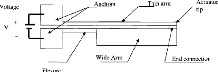
The thermal microactuator produces deflection due to the asymmetric thermal expansion of the two arms Figure-1.1). Upon application of a potential difference, the thin arm expands more than the wide arm, leading to motion of the actuator tip towards the wide arm.
Figure 1.1 : Geometry of the thermal actuator
Stress-strain Analysis of a Micro Thermal Actuator by
Finite Element Method
1
BANDIKOLLA AKSHAY, 2 Dr.CHEPURI SRINIVASA RAO,
1
M.Tech., Scholar, Dept. of Mechanical Engineering, KHIT,Guntur, A.P., INDIA 2
Micro-Electro-Mechanical (MEMS) offer the possibility of reducing entire complex engineering systems to the micro-scale domain [1].. The electrostatic actuators have been extensively studied and have found wide applications due to their low power and high frequency [2, 3].
Based on COMSOL Multiphysics software, an analysis of an innovative thermal actuation has been used for electrostatic comb drive [4]. Actuators based on electrostatic forces operate at low power and high frequency, and are highly desirable [5]. Polysilicon thermal actuators can operate in an integrated circuit (IC) current/voltage regime and may be fabricated by a surface micromachining technology that is compatible with IC technology [6].
Throughout the simulations, a 2D radiation model of the array has then been used to monitor the effect of varying the displacement on the radiator temperature [7].The simulation shows that, with a single thermal actuator, only the shutter array of a geometry-limited radiator can be controlled. However, the feasibility of thermal actuators for thermal control applications has been proved, and the results obtained with the present study increase our knowledge about optimized thermal [9].
Electrostatic actuation is widely adopted in MEMS devices among other methods of actuation (e.g. electro thermal, piezoelectric, etc.) [10]. Also, to achieve higher amplitude of actuation, it is necessary to increase the applied voltage [11]. One of the problems associated with increasing the applied voltage is the joule heating effect [12]. An increase in the temperature of electro statically actuated MEMS device can greatly affect the performance of the device. This heating side effect will result in different problems such as, generating thermal stresses [13], straining the microstructure, and even changing the mechanical properties of the vibrating structure material which result in changing the expected resonance frequency of the device [14]. Thermal micro -actuators are a very popular actuation technology in MEMS. They commonly exploit differential thermo mechanical expansion of materials, known as the thermo mechanical effect, resulting generally from Joule heating [15]. The operating principle of a thermally driven actuator with lateral motion (parallel to the substrate) is the asymmetrical thermal
expansion of a microstructure with variable cross sections [16].
2.0 FINITE ELEMENT MODELING AND ANALYSIS
The geometric design parameters of the actuator are shown in Figure-2.1. All the parameters represented are in microns. The wide arm of the modeled parameter is on the top side instead as shown in Figure-2.1. The dimensional values of the actuator are shown in Table-2.1.
Figure 2.1: Geometric design parameters of the thermal microactuator
The 3-dimensional element SOLID227 with thermal conduction capability has been used for discretization. The element has eight nodes with a single degree of freedom, temperature, at each node. The element is applicable to a 3-D, steady-state or transient thermal analysis. The element also can compensate for mass transport heat flow from a constant velocity field. If the model containing the conducting solid element is also to be analyzed structurally, the element should be replaced by an equivalent structural element. The element simulates the coupled thermal-electric-structural response. A mesh size of 0.1 has been used for discretization. The meshing is refined at the places where there is a change in cross section. The geometry of the element is as shown in Figure- 2.2
The element has ten nodes with up to five degrees of freedom per node. Structural capabilities include elasticity, plasticity, hyperelasticity, viscoelasticity, viscoplasticity, creep, large strain, large deflection, stress stiffening effects, and prestress effects
Table-2.1.: The dimensional values of the actuator
Figure -2.2.: Solid 227 geometry
The solid model has been shown in Figure-2.3. The mesh of the model in X-direction for 2D view is shown in Figure-2.4. The oblique view of the meshed model is shown in Figure-2.5.
Figure-2.3: the geometry to be modeled.
To define material properties for this analysis, it must be converted the given units for Young's modulus, resistivity, and thermal conductivity to μMKSV units. The units have been converted to μMKSV. The bottom surfaces of the anchors are fixed in all degrees of freedom to simulate the practical bonding situation . Electrical power with different voltage is applied at the bonding pads so that current passes
Figure-2.4: Mesh of the actuator in 2D –X direction
1
X
Y Z
MEMS Thermal Actuator OCT 25 2016
14:18:28 ELEMENTS
Figure-2.5: Mesh of the actuator in Oblique view.
Temperature gradient develops due to thermal conduction and thermal convection occurs on the boundary surfaces where 25◦ C is assumed as the ambient temperature. It is assumed that the polysilicon is homogeneous, linear and isotropic with a Young’s modulus E=170 GPa. Residual stresses and warping resulting from fabrication process are ignored. The coefficient of heat conduction is 0.034 W mm− 1
◦ C− 1 and the coefficient of natural convection is 50 μW mm− 2 ◦ C− 1.
3.0 RESULTS AND DISCUSSION
The stresses are developed due to potential difference between the two pads. The principal stresses in X, Y and Z-directions are measured for the voltage variation from 5V to 15V at the temperature of 40°C. The stress is maximum in X-direction i.e., along the length of the actuator when compared the stresses along width and thickness directions. The maximum stress developed is 82 N/mm2. Figure-3.1 shows the variation of principal stresses with voltage at 40°C. Notation Width of thin arm Width of wide arm Thickness of flexure Width of flexure Length of wide arm Item d1 d2 d 3 d4 d5 Dimension value (μm) 40 255 40 330 1900 Item d6 d7 d8 d9 d11a Dimension value (μm) 90 75 352 352 20
Figure-3.1: Voltage vs.Normal stress
The distribution of the Von mises stresses in the actuator at a temperature of 40 °C obtained by ANSYS simulation is shown in Figure-3.2. The blue color stands for less stress values and red color stands for the region of higher stresses. It is clearly depicted that the stress is more concentrated on the flexure region of the actuator. The maximum value of von mises stress is 98.5405 MN/m². The tip of the arm has displaced through 2.96942 μm.
Figure-3.2: Von mine stress at a pad temperature of 40°C and 5V
The von mises stresses are more in X-direction i.e., along the length of the actuator when compared to width and thickness directions. The variation of von mises stresses and Shear stresses in X,Y and Z-directions are as shown in Figure- 3.3 and 3.4 respectively. It is observed that the von mises stresses are more in X-direction and Shear stresses are more in XZ plane.
The thermal stresses developed in the actuator due to potential difference also causes deformation of the actuator in Y-direction. This deformation is an indirect measurement by von mises strains.
The principal strains in X, Y and Z-directions are measured for the voltage variation from 5V to 15V at the temperature of 40°C. The strain in X-direction is gradually increasing with voltage, where as the strain in Y and Z directions is steep raising. Figure-3.5 shows the variation of principal strains with voltage at 40°C.
Figure- 3.3: Voltage vs. Von mises stress
Figure-3.5: Voltage vs. Normal strain
The variation of von mises strains and Shear strains in X,Y and Z-directions are as shown in Figure- 3.6 and 3.7 respectively. It is observed that the von mises strains are more in X-direction and Shear strains are more in XZ plane.
Figure-3.6:Voltage vs. Von mises strain
Figure-3.7:Voltage vs. Shear strain
The von mises strains in the actuator at a pad temperature of 40°C and voltage of 5V is shown in Figure-3.8: The figure shows that the maximum strain value is .588E-03μm. The
displacement of the actuator is 2.96942 μm. The maximum strain happens in the area of the flexure as shown in figure.
Figure- 3.8: Von mises strain at a pad temperature of 40°C and 5V
Similarly, some of the simulated results for the distribution of von mises stresses and strains at other pad temperatures and voltages are shown in the following figures.
Figure- 3.9: Von mises stress at a pad temperature of 40°C and 7V
(von mine stress minimum value .085053 M N/M² , Von mine stress maximum value 160.81 M N/M², The actuator
Figure- 3.10: Von mises strain at a pad temperature of 40°C and 7V
(von mine strain minimum value .719E-06, Von mine strain maximum value .965E-03, The actuator displacement 5.91657 μm)
Figure- 3.11: von mine stress at a temperature of 40°C &13V (von mine stress minimum value .201548 M N/M², Von mine
stress maximum value 561.569 M N/M², The actuator displacement 20.6527 μm)
Figure- 3.12: von mine strain at a temperature of 40°C &13V
(von mine strain minimum value .213E-05, Von mine strain maximum value .003371, The actuator displacement 20.6527
μm)
Figure- 3.13: Von mine stress at a pad temperature of 40°C and 15V
(von mine stress minimum value .20915 M N/M², Von mine stress maximum value 748.59 M N/M², The actuator
displacement 27.5297 μm)
Figure- 3.14.: Von mises strain at a pad temperature of 40°C and 15V
(von mine strain minimum value .213E-05, Von mine strain maximum value .004494, The actuator displacement 27.5297
μm)
CONCLUSION
A three-dimensional model of a MEMS micro thermal actuator has been developed using a finite element analysis simulation code ANSYS 15.0 software. Thermo-mechanical simulations have been carried out with Poly-Silicon (Poly-Si)
material. The deflection, stress and temperature analyses have been carried out for a range of applied voltages within 15V.
REFERENCES:
[1] Dong Yan, “Mechanical design and modeling of MEMS thermal actuators for RF applications”, 2002, University of Waterloo, Waterloo.
[2] L.A. Field, D.L. Burriesci, P.R. Robrish, R.C. Ruby, “Micromachined 1X2 optical fiber switch”, Sensors and Actuators, vol. 53, pp. 311–315, 1996.
[3] M. Hoffman, P. Kopka, T. Groß, E. Voges, “All-silicon bistable micromachined fiber switches”, Electron. Lett., vol. 34, pp. 207–208, 1998.
[4] S. Pathneja and P. Raja, Analysis and Optimization of an Electro-Thermally and Laterally Driven Poly-Silicon Micro-Actuator, Int. Journal of Engineering Research and Applications Vol. 4, pp. 34-37 (2014).
[5] S. Kaur et al., Application Of Thermal Actuator, International Journal of Advanced Research in Computer and Communication Engineering, Vol. 2, Issue 10 (2013).
[6] Q-A. Huang and N. K. S. Lee, Analysis and design of polysilicon thermal flexure actuator J. Micromech. Microeng., Vol. 9, pp. 64–70 (1999).
[7] D. Farrar et al., Controlling Variable Emittance (MEMS) Coatings for Space Applications, Inter Society Conference on Thermal Phenomena (2002).
[8] R. Osiander et al., Microelectromechanical Devices for Satellite Thermal Control, IEEE Sensors Journal, Vol. 4, pp. 525-531 (2004). [9] A. G. Darrin et al., Variable Emissivity through MEMS Technology, Inter Society Conference on Thermal Phenomena (2000).
[10] M. Hassan, Electrostatically actuated 3C-SiC MEMS for frequency mixing, Journal of Mechatronics, Vol. 1, pp.21–24, 2012 [11] L. Jiang, R. Cheung, M. Hassan, A.J. Harris, J.S. Burdess, C.A. Zorman and M. Mehregany, "Dry release fabrication and testing of SiC electrostatic cantilever actuators", Microelectronic Engineering, pp.78-79, 2005
[12] A. R. Kalaiarasi and S. Hosimin Thilagar, “Modeling and characterization of a SOIMUMP’s hybrid electro thermal actuator”, journal of microsystem technologies, 19(1), pp. 113-120, 2013. [13] M. Hassan, “Determination of residual stresses in a single crystalline 3C-SiC micro-fabricated structure using FE model and measured resonance frequencies”, Journal of Microsystem Technologies, Vol.18, No.3, 2012
[14] M. Pozzi, Musaab Hassan, Alun J Harris, Jim S Burdess, Liudi Jiang, Kin K Lee, Rebecca Cheung, Gordon J Phelps, Nick G Wright, Christian A Zorman and Mehran Mehregany, “Mechanical properties of a 3C-SiC film between room temperature and 600 °C”, J. Phys. D: Appl. Phys. 40 No 11, pp.3335-3342, 2007
[15] J. R. Serrano, L. M. Phinney, J. W. Rogers, “Temperature amplification during laser heating of polycrystalline silicon microcantilevers due to temperature-dependent optical properties”, International Journal of Heat and mass Transfer, vol. 52, pp. 225-226, 2009.
[16] Qing-An Huang, Neville Ka Shek Lee, “Analysis and design of polysilicon thermal flexure actuator”, J. Micromech. Microeng, vol. 9, pp. 64-70, 1999.
B. Akshay, M.Tech., Scholar in Thermal Engineering, Dept. of Mechanical Engineering, KHIT, Guntur, A.P., INDIA, Mob. No:
Dr. Chepuri Srinivasa Rao, is a
Professor, Mechanical Engineering Dept., KHIT, Guntur, A.P., INDIA. Dr. Rao have published 45 research articles in various journals and conferences. He has 18 years of teaching experience and life Member of ISTE. Mob. No: 8790931628