4157 ISSN: 2278 – 7798 All Rights Reserved © 2015 IJSETR
Efficient architecture of CORDIC to implement DIT-FFT
K.NIKHILESH
M.TECH VLSI DESIGN JNTUK Dr.M.SAILAJA MS(u.s.a),Phd PROFESSOR JNTUK
Abstract— This paper discusses different hardware implementation of the Co-ordinate Rotation Digital Computer algorithm. Optimized designs for vector rotation through specific angles and different CORDIC circuits for fixed and known angle rotation at different levels of accuracy. Hardwired pre-shifting scheme in barrel shifter is given for reducing area and time complexity. Pipelined schemes are used by cascading single rotational CORDIC units to obtain high throughput and reduce latency. Reference CORDIC circuit is also given where the registers are updated at each stage to avoid more hardware. In this paper an efficient CORDIC circuit is proposed where Carry Look Ahead adder is used to replace adder unit, in order to reduce the area. Out of many applications of CORDIC algorithm, this paper presents the basic idea of using CORDIC algorithm instead of the multipliers for implementing FFT. Comparison of area requirement of different architectures are tabulated. Verilog HDL Code is simulated using modelsim and synthesized using Xilinx 14.4.
Keywords— Coordinate Rotational DIgital Computer (CORDIC), Carry look ahead adder, pipelineing,FFT(fast fourier transform).
I. INTRODUCTION (CORDIC)
CORDIC (Coordinate Rotation Digital Computer) is a method for computing elementary functions using minimal hardware such as shifts, adds/subs and compares. CORDIC works by rotating the coordinate system through constant angles until the angle is reduces to zero. The angle offsets are selected such that the operations on X and Y are only shifts and adds.
Here we describe the mathematics behind the CORDIC algorithm. The CORDIC algorithm
performs a planar rotation. Graphically, planar rotation means transforming a vector (Xi, Yi) into a resultant vector (Xj, Yj) as shown in fig 1.
Using a matrix form, a planar rotation for a vector of (Xi, Yi) is defined as
i i j j Y X Y X cos sin sin cos (1)
The angle rotation can be executed in several steps, using an iterative process. Each step completes a small part of the rotation. Many steps will compose one planar rotation. A single step is defined by the following equation, i.e. modifying (1) by eliminating the cosnfactor.
n n n n n n n Y X Y X 1 tan tan 1 cos 1 1 (2)
Equation 2 requires three multiplies, compared to the four needed in equation 1.
Additional multipliers can be eliminated by selecting the angle steps such that the tangent of a step is a power of 2. Multiplying or dividing by a power of 2 can be implemented using a simple shift operation.
n
cos Coefficient in the algorithm has been reduced to a few simple shifts and addition operation. The coefficient can be eliminated by pre-computing the final result. The first step is to rewrite the coefficient. The second step is to compute cosn for all values of „n‟ and multiplying the results, which we will refer to as K. 607253 . 0 ) cos( 1 n P K (3) Y X (Xj, Yj) (Xi, Yi)
4158 ISSN: 2278 – 7798 All Rights Reserved © 2015 IJSETR
K is constant for all initial vectors and for all values of the rotation angle, it is referred to as the congregate constant. The derivative P (approx. 1.64676) is defined here because it is commonly used.
We can now formulate the exact calculation the CORDIC performs.
sin cos sin cos i i j i i j X Y K Y Y X K X (4)Because the coefficient K is pre-computed and taken into account at a later stage, equation 8 may be written as n n n n n n n n n n X S Y Y Y S X X 2 1 2 1 2 2 (5) At this point a new variable called „Z‟ is introduced. Z represents the part of the angle which has not been rotated yet.
The angle for each step is given by
n n 2 1 arctan (6)
All iteration-angles summed must equal the rotation angle .
(7)
For every step of the rotation Sn is computed as a sign of Zn. 0 1 0 1 n n n Z if Z if S (8)
Combining equations 5 and 15 results in a system which reduces the not rotated part of angle to zero. Generalized CORDIC iteration in rotation mode:
xi+1= xi – di . 2-i . yi
yi+1 = yi + di . 2-i . xi (9)
zi+1 = zi – di . tan-1(2-i)
This algorithm is commonly referred to as driving Z to zero. The CORDIC core computes:
Xj,Yj,Zj
P
Xicos
Zi Yisin
Zi
,P
Yicos
Zi Xisin
Zi
,0
(10)
Sine and Cosine can be calculated using the first CORDIC scheme which calculates:
By using the following values as inputs 60725 . 0 K Xi 0 i Y i Z
The core calculates:
Xj,Yj,Zj
cos,sin,0
(11)The input Z takes values from –180degrees to +180 degrees where:
0x8000 = –180degrees 0xEFFF = +80degrees
But the core only converges in the range –90degrees to +90degrees.
The remainder of this paper is organized as follows. Section II deals with the implementation of rolled CORDIC algorithm, Hardwired pre-shifting schemes in barrel shifter for implementing CORDIC algorithm and pipelined CORDIC algorithm to increase throughput. Section III deals with implementing CORDIC algorithm using carry look ahead adder (CLA). Section IV Presents the basic idea of using CORDIC algorithm in implementing DIT-FFT. Section V schematics and waveforms of different architectures discussed. Section VI Presented the comparison table of area complexity of the architectures. Section VII Conclusion. Section VII references used.
II. EXISTING DESIGN
A. Reference folded CORDIC algorithm:
A folded design is an iterative parallel design obtained by duplicating each of different equations in hardware as shown. Each individual unit consists of shifter, registers and add/sub unit. Registers are used for holding the computed values at each iteration. A folded CORDIC circuit for vector rotation is shown in Fig 2. Where X0, Y0 are set/reset inputs to
the registers X, Y respectively. Feedback is fed successively at every ith iteration through Xi and Yi, parallel to the input registers. The X and Y branch
0 n n n S Where Sn
1;1
4159 ISSN: 2278 – 7798 All Rights Reserved © 2015 IJSETR
signals are through the shifter units and the add/sub unit.
The direction of rotation is determined in branch of variable Z, where Z0 is initialized with the angle to
which the vector is to be rotated. And a add/sub unit is combined with the look up table whose address is changed according to the number of iteration.
Since the adder/sub unit and the shifter unit in each path share the latency of the output. This conventional method is not well suited for high speed application. But it is a wise choice while area optimization is major concerned.
B. Unfolded CORDIC design:
Previously discussed architecture is iterative nature, which requires iterations to be performed n times the data rate. A direct approach of designing a parallel processing architecture is discussed here that uses pipeline implementation as shown in figure 3. In this implementation the output of previous stage is fed as input to next stage.X0, Y0, Z0 represents the inputs
and Xn, Yn, Zn represents the output values.
Major changes in this implementation are, the shifter in each unit is of constant shift at each stage. ROM usage in previous design is eliminated as the constant values are hardwired i.e. ϕ.
C. Hardwired preshifting CORDIC design:
Similar to the unfolded CORDIC design except for a barrel shifter of S shifts, L length of word require log(S+1) stages of de-multiplexers. Hence hardware complexity increases linearly with word length and logarithmically with number of shifts. In order to reduce the complexity of barrel shifter we use simple hardwired pre shifting as shown in figure 3.In
hardwired shifting if l bits are to be shifted ,we load only L-l MSB bits and the remaining l MSB bits are hardwired to 0. Hence the output of barrel shifter are loaded as L-l LSB to add/sub module and l MSB are hardwired to 0. SBR is sign bit register usually set to 1 or 0 depending upon the sign of Zi.
In hardwired pre-shifting it would reduce the number of shifts, so hardware complexity and delay of shifter can be reduced.
Register Register Register
+/- +/- +/-
Register Register Register
+/- +/- +/-
Register Register Register
+/- +/- +/-
Register Register Register
+/- +/- +/- >>0 >>0 >>1 >>1 >>2 >>2 >>n >>n x0 y0 z0 Xn Yn Zn ϕ0 ϕ1 ϕ 2 ϕ n
III. PROPOSED WORK
A. CORDIC design using CLA:
Since CORDIC algorithm uses adder circuit several times during the process. Implemented Fig 2: Reference rolled CORDIC circuit
Fig 4: Hardwired pre-shifting CORDIC circuit Fig 3: Unfolded pipelined CORIDC circuit
4160 ISSN: 2278 – 7798 All Rights Reserved © 2015 IJSETR
CORDIC using CLA differs from other architecture in terms of area, latency and power.
Carry look ahead adder module is used in CORDIC algorithm for performing add/sub operation. For performing subtraction operation 2‟s complement of the subtracted. Since add/sub operation are used in implementing CORDIC process, we desire that the adder module is performed fast and low latency. Hence we go for Carry look ahead adder since there is no carry propagation delay and propagation delay is equal to the delay of full adder.
Generalized equation for implementing carry look ahead adder are
Generate signal: gi = xi . yi Propagate signal: pi = xi
yi Sum: Si = pi
ciCarry: Ci+1 = gi + ci . pi IV. APPLICATION WORK
Evaluation of trigonometric functions are major requirement in signal processing algorithms. Traditionally these functions are implemented using multiplication and accumulation unit, consisting of adders, multipliers, registers.
CORDIC algorithm has been an efficient way of evaluating the trigonometric, exponential, hyperbolic functions. It can also be used for performing complex multiplication by using just add and shift operation. In this paper we implement 2 bit FFT algorithm using CORDIC core, basic butterfly unit of decimation-in-time calculation used for FFT calculation is shown in fig (5).CORDIC evaluates rotational functions more accurately compared to other methods.
V. SECTION V(SCHEMATIC AND WAVEFORM)
Fig 5: Hardwired pre-shifting CORDIC circuit
Schematic 1: Folded CORDIC design
Schematic 2: pipelined CORDIC design
Schematic 3: unfolded CORDIC design
4161 ISSN: 2278 – 7798 All Rights Reserved © 2015 IJSETR
VI. COMPARISION TABLES
COMPARISION TABLE 1:AREA UTILIZATION OF DIFFERENT CORDIC ARCHITECTURES
Folded Pipeline Hardwi red Proposed Availa ble No slice s 981 (20%) 839 (17%) 710 (14%) 70 (1%) 4800 No slice F/F‟ s 1026 (42%) 2368 (98%) 755 (31%) 353 (14%) 2400 No 4 inpu t LUT S 955 (90%) 782 (32%) 641 (77%) 60 (16%) 1052 No boun ded IOS 99 (97%) 98 (96%) 82 (80%) 84 (82%) 102
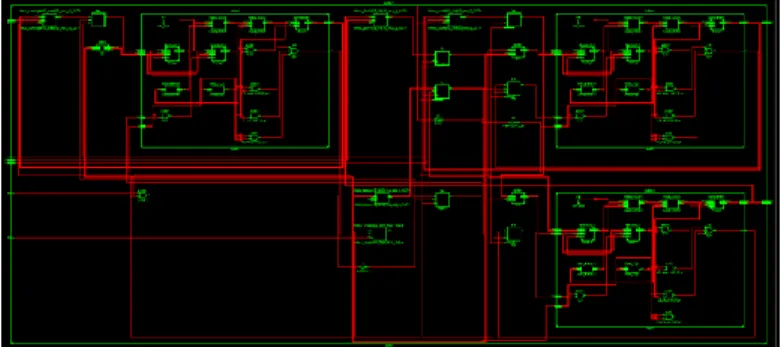
Schematic 5: DIT-FFT using CORDIC design
Simulation result 1: Folded CORDIC design
Simulation result 2: unfolded CORDIC design
Simulation result 3: hardwired CORDIC design
Simulation result 4: CORDIC design using CLA
4162 ISSN: 2278 – 7798 All Rights Reserved © 2015 IJSETR
COMPARISIONTABLE2:MEMORYUTILIZATIONOF DIT-FFT
COMPARISIONTABLE3:AREA UTILIZATION OF DIT-FFT
VII. CONCLUSION
Different architectures of CORDIC algorithm are implemented on FPGA platform Spartan6 using Xilinx tool, it is observed that the number of slices, registers and LUTs required are reduced significantly. Implementation of DIT-FFT using CORDIC is studied and tabulated the results, from which the area utilization is reduced. Also the amount of memory
required for implementing the design is reduced by about 1088 KB.
VIII. ACKNOWLEDGEMENT:
I highly indebted to Dr.M.Sailaja, Professor in JNTU Kakinada for guiding me as well as for providing necessary information regarding the project and also support in completing project.
REFERENCES
[1] Andraka, R. A survey of CORDIC algorithms for FPGA based computers, FPGA98, ACM/SIGDA International Symposium on Field Programmable Gate Arrays, pp 191-200, 1998.
[2] J. E. Volder, “The CORDIC trigonometric computing technique,” IRE Trans. Electron. Comput., vol. EC-8, pp. 330– 334, Sep. 1959.
[3] Y. H. Hu, “CORDIC-based VLSI architectures for digital signal processing,”IEEE Signal Process. Mag., vol. 9, no. 3, pp. 16–35, Jul.1992.
[4] P. K. Meher, J. Valls, T.-B. Juang, K. Sridharan, andK. Maharatna, “50years of CORDIC: Algorithms, architectures and applications,” IEEE Trans. Circuits Syst. I, Reg. Papers, vol. 56, no. 9, pp. 1893–1907, Sep.2009.
[5] Y.H. Hu, “Pipelined CORDIC architecture for the implementation of rotational based algorithm,” in Proceedings of the International Symposium on VLSI Technology, Systems and Applications, p. 259, May 1985.
[6] European Journal of Advances in Engineering and Technology, 2015, 2(6): 98-102.
[7]A CORDIC Processor for FFT Computation and Its Implementation Using Gallium Arsenide Technology.VOL. 6, NO. 1, MARCH 1998.
DIT-FFT FOLDE D PIPELI NED HARDWI RED PROPOSE D MEM ORY 19211 2 KB 18864 8 KB 186344 KB 185256 KB
FOLDED PIPELINE HARDWI RED PROPOS ED AVAI LABL E NO SLICES 642 (5%) 550 (4%) 184 (1%) 137 (1%) 114 40 NO SLICE F/F‟S 720 (12%) 1597 (27%) 262 (4%) 207 (3%) 572 0 NO 4 INPUT LUTS 601 (78%) 510 (31%) 145 (12%) 33 (15%) 163 7 NO BOUNDE D IOS 106 (53%) 65 (32%) 106 (53%) 107 (53%) 200