GALGOTIAS UNIVERSITY
Plot No.2, Sector 17-A, Yamuna Expressway,
Greater Noida, Gautam Buddh Nagar, U.P., India
School of Computing Science & Engineering
P
RACTICAL
F
ILE
Course Name : ………
Course Code : ………
School : ………
Program ……….Batch : ………
Year/Semester : ………. Session: ……...……
Submitted By:
Name: ………...
Roll No: ………
Submitted To:
……….
……….
Table of Contents
S.No. Name of the Experiment
Date
Page
No.
Signature
of Faculty
Remar
k
1
Studying Various phases of Water-Fall Model
2
Prepare SRS for Banking or On line book store
domain problem.
3 Perform SA/SD for the following software. • Hotel Automation System
• Book Shop Automation Software • Word processing Software
• Software Component Cataloguing Software. 4 Draw E-R diagram, data-flow diagram,
state-transition diagram for the project.
5 Calculate effort using FP oriented estimation model.
6 Design an algorithm that will prompt for and receive your age in years and month and calculate and display your age in months. If the calculated months figure is more then 500, three asterisks should also appear beside the month figure. Your program is to continue processing until a sentinel of 999 is entered.
7
Using COCOMO model estimate effort for Banking Management System.8
Design an algorithm that will prompt for and receive the measurement for the diameter of a circle, and calculate and display the area and circumference of that circle.9
Development of Software tool for Halstead
Analysis.
10
Research on Case Studies:
• Online Admission System
• Purchase Order System
• Railway Reservation System
• Bill Tracking System
Lab Assignment 1: Studying Various phases of Water-Fall Model
This model is easy to understand and reinforces the notion of “define before design” and “design before code”. The model expects complete & accurate requirements early in the process, which is unrealistic.
One of the main advantages of the waterfall model is its simplicity. It is conceptually straightforward and divides the large task of building a software system into a series of cleanly divided phases, each phase dealing with a separate logical concern. It is also easy to administer in a contractual setup—as each phase is completed and its work product produced, some amount of money is given by the customer to the developing organization.
The waterfall model, although widely used, has some strong limitations. Some of the key limitations are:
1. It assumes that the requirements of a system can be frozen (i.e., baselined) before the design begins. This is possible for systems designed to automate an existing manual system. But for new systems, determining the requirements is difficult as the user does not even know the requirements. Hence,
having unchanging requirements is unrealistic for such projects.
2. Freezing the requirements usually requires choosing the hardware (because it forms a part of the requirements specification). A large project might take a few years to complete. If the hardware is selected early, then due to the speed at which hardware technology is changing, it is likely that
the final software will use a hardware technology on the verge of becoming obsolete. This is clearly not desirable for such expensive software systems.
3. It follows the “big bang” approach—the entire software is delivered in one shot at the end. This entails heavy risks, as the user does not know until the very end what they are getting. Furthermore, if the project runs out of money in the middle, then there will be no software. That is, it has the “all or nothing” value proposition.
4. It encourages “requirements bloating”. Since all requirements must be specified at the start and only what is specified will be delivered, it encourages the users and other stakeholders to add even those features which they think might be needed (which finally may not get used).
5. It is a document-driven process that requires formal documents at the end of each phase.
Lab Assignment 2: Prepare SRS for Banking Management System.
Solution:
BANK MANAGEMENT SYSTEM
PROBLEM STATEMENT:
“ABC Bank a nationalized bank wants to computerize some of its services. Banking services is really a complicated task. Each service has a process of its own to be carried out. To reduce the complexity the bank wants to computerize some of its services like maintenance of account holders’ details, their transactions, providing interest for fixed deposit account holders etc”.
The software created must get the information from the user. It should then give the user an option as what he wants to look into, like the details of the account holder, his transactions, interest calculated etc by selecting onto the correct option.
As the firm for which the software is to be created is a Bank, the various activities of the bank which the software must carry out is maintenance of account holders’ details, their transactions, interest calculation for fixed deposit account holders’ etc. The software created must allow the user to view the details of the account holder for each activity.
The software should calculate the interest for fixed deposit account holders’ as per the time given by the user. It should maintain every detail of the account holder.
SOFTWARE REQUIREMENTS SPECIFICATION:
1.
INTRODUCTION:
This document is to provide the software requirement specification of the computerized solutions for certain banking services. It keeps track of the account holder’s details. It calculates the interest rate for fixed deposit account holders’.
1.1. Purpose:
The main purpose of this software is to enable the easy maintenance of account holders’ details, their transaction etc.
1.2. Scope:
The software has the ability to keep a track on the account holders’ details.
1.2.1. Benefits:
Saves time. Reduce errors. Customer friendly.
1.2.2. Objectives:
Provides fully automated banking services. Efficient functioning of the bank.
1.3. Definitions, Acronyms And Abbreviations:
OS-Operating System
RAM-Random Access Memory MB-Mega Byte
GB-Giga Byte
Mbps-Mega bits per second HDD-Hard Disk Drive
BMS-Bank Management System LAN-Local Area Network
1.4. Reference:
The books and reference materials used during the pre-development stages of the project include:
Software Engineering: A Practitioner’s Approach By Roger.S.Pressman.
Software Engineering: Ian Sommerviel.
1.5. Overview:
The rest of this document gives an overview of the feature and functions of the bank management software along with the technical and non-technical details and the interfaces.
2. OVERALL DESCRIPTION:
2.1. PRODUCT PERSPECTIVE:
The “Bank Management System” is an application that remains to be independent. The system interfaces, user interfaces and the hardware interfaces related with this software is defined below:
2.1.1. System Interfaces:
The client system must be able to share the data available in the database through the network.
2.1.2. User Interfaces:
The screen formats and the menu structure should be in such a way that the user should find it easy to use the product. The product should be user-friendly. The functionality provided by the system like displaying error messages should adapt itself to the different users of the product.
2.1.3. Hardware Interfaces:
UPS (Uninterrupted Power Supply) for backup power during power failure. Client systems are connected to the LAN.
Since a LAN is to be used for the network wherein each node is connected to every other node.
2.1.4. Software Interfaces:
NAME
VERSION
SOURCE
MS-ACCESS
2000 or any other
higher version
Microsoft Corporation
OS-WINDOWS
2000 or any other
higher version
Microsoft Corporation
2.1.5. Communication Interfaces:
There is a LAN user for communication among the different client systems to be used.
2.1.6. Memory Constraints:
The system should require a disk space of 20 GB and 256MB RAM of the service systems and 5 GB and 128 RAM for the client system.
2.1.7. Operations:
The user can be a staff or an administrative manager. The user has to use a login to enter the software and then he/she can check the details of the account holders. There must be a backup data, which will enable easy recovery from failures, which may catastrophic at times by clicking on the menu.
2.1.8. Site Adaptive Requirements:
The software requires no special requirements to adapt to a particular installation except for files that are to be re-created.
2.2. PRODUCT FUNCTIONS:
The main functions are:
Create an account.
Maintain a track on the transactions made by the account holder. Calculate the interest for fixed deposit account holders.
Display the account holders’ details when required.2.3. USER CHARACTERISTICS:
It is enough that the user has a basic knowledge of C++ needed for the operation of the software. There is no need for any experience or technical knowledge.
2.4. CONSTRAINTS:
It is mandatory that no text box must be left empty or contains insufficient information.
Hardware Limitations:
There must be 128 MB on board memory.
Interface to other application:
Not applicable.
Parallel Operations:
It should support many users at a time.
Control functions:
In case of any errors and service problems proper error handling
and other recovery mechanisms must be used.
Higher order language Requirements:
Not applicable.
Signal Handshake Protocol:
Not applicable.
Reliability Requirements:
Data redundancy.
Safety and Security Considerations:
The application must always be exited normally.
2.5. ASSUMPTIONS AND DEPENDENCIES:
The requirements of the software product will be changed if suppose the features or the functions of the system are to be improved.
2.6. APPORTIONING OF REQUIREMENTS:
Not applicable.
3. SPECIFIC REQUIREMENTS:
3.1. EXTERNAL INTERFACE REQUIREMENTS:
3.1.1. User Interfaces:
The interface used in GUI must be easy to understand.
This interface serves as a bridge between the user and the software. It also
makes the user interaction with the system easy.
The user interface includes:
Screen formats / Organizations:
The introductory screen will be the first to be displayed which
allows the user to log in using their id and password.
Windows formats / Organizations:
When the user chooses a particular topic then the information
pertaining to that topic will be displayed in a new window, which will allow
multiple windows to be available on the screen, and the user can switch
between them.
Data Format:
The data entered by the user will be alphanumeric.
End Message:
When there are some exceptions, error messages will be
displayed promptly by the user to re-enter the details when an event has taken
place successfully.
3.1.2. Hardware interfaces:
The system must basically support certain hardware and these
must be an interface between them.
NAME OF THE ITEM
DESCRIPTION OF
PURPOSE
SOURCE OF INPUT /
DESCRIPTION OF
OUTPUT
Keyboard
To get the details of
from the user.
Source of input
Printer
To print the details of
the account holder.
Destination of output
3.1.3. Software interfaces:
Not applicable.
3.1.4. Communication interfaces:
Every client system connected through LAN establishes a
communication only with server and not with any client system. A LAN of 10
Mbps is used.
3.2. SOFTWARE PRODUCT FEATURES:
3.2.1. FEATURE 1:CREATING A NEW MEMBER:
The purpose of this feature is to create a new member detail
from the user.
3.2.1.1. Purpose:
The purpose of this feature is to enable the user to enable
him/her to enter the details of a new account holder.
3.2.1.2. Stimulus / Response sequence:
Once the request is made, a window will appear asking for all
personal details of the account holder as to begin a new account.
3.2.1.3. Associated functionality requirement:
3.2.1.3.1. Functional requirement: Creating a new member:
It must check ensure that the user enters valid information and
display error messages to avoid abnormal interrupts.
3.2.1.3.1.1. Introduction:
The user must be provided with the text and entry box within
10 seconds.
3.2.1.3.1.2. Inputs:
The user has to enter the member id, name of the account
holder, address, phone number, nature of account (whether savings or fixed),
document produced for address proof, registration number of the address proof. It
also asks if the user wants to add new members.
3.2.1.3.1.3. Processing:
Recognizing the correct input as given by the user.
3.2.1.3.1.4. Outputs:
The page corresponding to the chosen feature will be displayed.
3.2.2.FEATURE 2:CREDIT/DEBIT (Making transactions):
This feature is to keep a track on the transaction made by the
account holder.
3.2.2.1. Purpose:
The purpose of this feature is to keep on the transactions made
by the account holder. If the A/C holder credits some amount, the amount gets
added up to his account. If he withdraws some amount from his account, then that
amount is subtracted from his account. It’s compulsory that the account holder
must maintain a minimum balance of Rs. 500 in his account.
3.2.2.2. Stimulus / Response Sequence:
Once the user chooses that option, the page corresponding to
that is to be displayed.
3.2.2.3. Associated Functionality Requirements:
3.2.2.3.1. Functionality Requirement: Transactions:
Once the user chooses the respective feature in the page, they
should be taken to the appropriate section establishing them to view the
corresponding page.
3.2.2.3.1.1. Introduction:
The user has to enter the date on which the A/C holder is
making the transaction.
3.2.2.3.1.2. Inputs:
The user has to enter member id of the A/c holder and the date
on which the transaction is made. The user must enter the nature of transaction
made (whether credit or debit) and the amount.
3.2.2.3.1.3. Processing:
Considering the given input to be correct if the nature of
transaction is credit then the amount is added to the account else it taken from the
account.
3.2.2.3.1.4. Outputs:
The required change is made in the account.
3.2.3. FEATURE 3: INTEREST CALCULATION:
The feature is to calculate the interest for fixed deposit account
holders.
3.2.3.1. Purpose:
The purpose of this feature is to calculate the interest amount
for fixed deposit account holders according to the time given by the user.
3.2.3.2. Stimulus / Response Sequence:
The user will be asked to enter the membership number, the
software will calculate the interest.
3.2.3.3. Associated Functionality Response:
3.2.3.3.1. Functionality Requirement 3:
If any one of the details provided by the user does not meet the defined
parameters then it would notify the user by displaying error messages.
3.2.3.3.1.1. Introduction:
The user can check about the details on the number of years
since the account has been started.
3.2.3.3.1.2. Inputs:
The user has to enter the member id, date, number of years
since the account has been started and the rate of interest provided by the bank.
3.2.3.3.1.3. Processing:
Recognizing the correct input as given by the user and to
calculate the interest payable by the bank to the account holder.
3.2.3.3.1.4. Outputs:
The output is generated in such way that the amount is added up to
account of the respective A/c holder.
3.2.4. FEATURE 4:-DISPLAYING A/c HOLDERS’ DETAILS:
3.2.4.1. Purpose:
The purpose is to enable the user to view the details of the respective
account holder’s details as entered by the user.
3.2.4.2. Stimulus / Response:
When the user requests to view the details of a particular account holder, a
screen prompts the user asking whether he want s o view the member details or to
view the transaction details.
3.2.4.3. Associated Functional Requirement:
3.2.4.3.1. Functional Requirements:-Displaying A/c holders’ details:
If invalid membership number has been entered, the system must handle the
error and ask the user to enter the proper input.
3.2.4.3.1.1. Introduction:
The user must be provided with the requested information within 10
seconds.
3.2.4.3.1.2. Inputs:
The user must enter the correct option whether he wants to view the
member details or the transaction details.
3.2.4.3.1.3. Processing:
Recognizing the correct option chosen by the user.
3.2.4.3.1.4. Output:
Displays the output with corresponding to the option chosen by the
user.
3.3. PERFORMANCE REQUIREMENTS:
A large database should be present as large data will be stored.
3.4. DESIGN CONSTRAINTS:
Requires 256 MB onboard memory.
Based completely on windows functionality performance.
The software must be valid and accessible only by authorized users.
3.5. SOFTWARE SYSTEM ATTRIBUTES:
3.5.1. Reliability:
The factors needed to establish the software expected reliability
are:
The user inputs should be valid and within the given range
Normal termination of the program
3.5.2. Availability:
The factors that generate the software availability include
proper termination and correct input details. Also the resource used for the project
development is Microsoft certified which speaks of the high quality standards.
3.5.3. Security:
It must ensure that the access is provided to authorized users only through
password.
The user of the service will provide network security.
3.5.4. Maintainability:
Implementing the concept of modularity, which in turn reduces
the complexity involved in maintaining it, will develop the software.
3.5.5. Portability:
The application is very adaptable; it can be used in different
computer systems with different operating systems and folders.
3.6. LOGICAL DATA BASE REQUIREMENTS:
The system requires the use of text file to maintain the account details
about the customer which includes the basic details of the customer and the
account details.
3.7. OTHER REQUIREMENTS:
NIL.
4. INDEX:
5. APPENDICES:
NIL
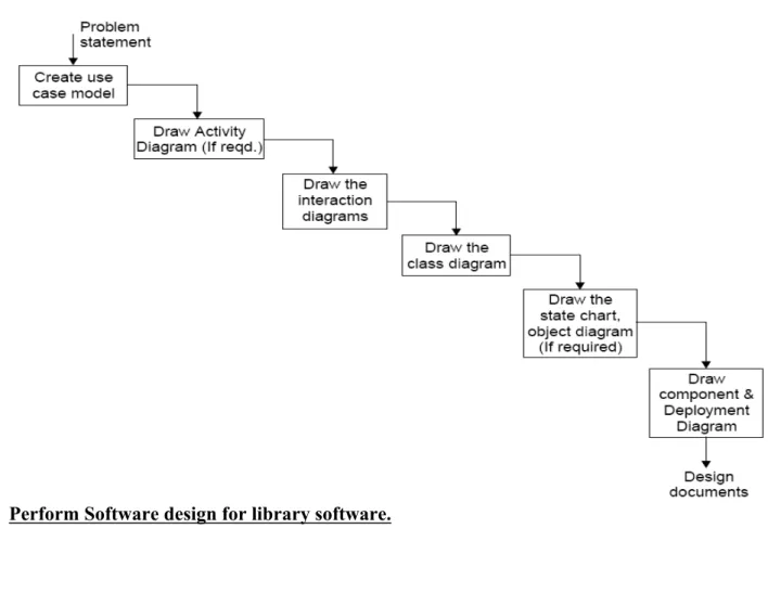
Lab Assignment 3: Perform SA/SD for the following software for a library system.
Case: A library System
The system should also be able to generate reports regarding the details of the books available in the library at any given time. The corresponding printouts for each entry (issue/return) made in the system should be generated. Security provisions like the ‘login authenticity should be provided. Each user should have a user id and a password. Record of the users of the system should be kept in the log file. Provision should be made for full backup of the system.
Fig: Performing Steps for analysis & design a software system
Lab Assignment 4: Draw E-R diagram, data-flow diagram, state-transition diagram for the
project.
2.3.1 Entity Relationship Diagram
An entity relationship diagram (ERD) is one means of representing the objects and their relationships in the data model for a software product.
Entity Relationship diagram notation:
To create an ERD you need to:
Define “objects” by underlining all nouns in the written statement of scope:
producers/consumers of data, places where data are stored, and “composite” data items.
Define “operations” by double underlining all active verbs: processes relevant to the
application and data transformations.
Consider other “services” that will be required by the objects.
Entity Then you need to define the relationship which indicates “connectedness”: a "fact" that
must be "remembered" by the system and cannot be or is not computed or derived
mechanically.
Data Flow Diagram
A data flow data diagram is one means of representing the functional model of a software product. DFDs do not represent program logic like flowcharts do.
Data flow diagram notation:
To create a DFD you need to:
Review ERD to isolate data objects and grammatical parse to determine operations.
Determine external entities (producers and consumers of data).
Create a level 0 DFD “Context Diagram” (one single process).
Balance the flow to maintain data flow continuity.
Develop a level 1 DFD; use a 1:5 (approx.) expansion ratio.
Data Flow Diagram Guidelines:
All icons must be labeled with meaningful names.
Always show external entities at level 0.
Always label data flow arrows.
Do not represent procedural logic.
Each bubble is refined until it does just one thing.
2.1 State Transition Details
A state transition may have an action and/or guard condition associated with it and it may also trigger an event.
An action is the behavior that occurs when the state transition occurs. An event is a message that is sent to another object in the system.
External entity
Process
Data flow Control flow
A guard condition is a Boolean expression of attribute values that allows a state transition only if the condition is true.
Both actions and guards are behaviors of the object and typically become operations. Also they are usually private operations (used by the object itself)
Actions that accompany all state transitions into a state may be placed as an entry action within the state.
Actions that accompany all state transitions out of a state may be placed as exit actions within the state
A behavior that occurs within the state is called an activity.
An activity starts when the state is entered and either completes or is interrupted by an outgoing state transition.
A behavior may be an action, or it may be an event sent to another object. This behavior is mapped to operations on the object.
State transition diagram notation:
Event causing transition Action that occurs New State [entry:…] [d ] State [entry:…] [d ]
Lab Assignment 5: Calculate effort using FP oriented estimation model.
Bank management system
Function oriented software metrics measure of the functionality delivered by
the application as a normalization value. Function oriented metrics were first
proposed by Albrecht, who suggested a measure called the function point. Function
points are derived using an empirical relationship based on countable [direct]
measures of software’s information domain and assessments of software
complexity.
Formula
FP=count total*[0.65+ (0.01*Fi)]
Function point count for bank management
General System characteristics
Fi
General system
Characteristics
Adjustment factor
Value
F1
Data communications How many communication
facilities are there to aid in the
transfer or exchange of
information with the application
3
F2
Distributed data
Processing
How are distributed data and
processing functions handled?
2
F3
Performance
Did the user require response
time or throughput?
1
F4
Heavily used
Configuration
How heavily used is the current
hardware platform where the
application will be executed?
2
F5
Transaction rate
How frequently is transactions
executed daily, weekly, monthly,
etc.?
3
F6
On line data entry
What percentage of the
information is entered online?
0
F7
End user efficiency
Was the application designed for
end user efficiency?
4
F8
On line update
How many ILF’s are updated by
online transaction?
0
F9
Complex processing
Does the application have
3
extensive logical or
mathematical processing?
F1
0
Reusability
Was the application developed
to meet one or many user’s
needs?
2
F1
1
Installation ease
How difficult is conversion and
installation?
2
F1
2
Operational ease
How effective and/or automated
are start up, back up and
recovery procedures?
2
F1
3
Multiple sites
Was the application specifically
designed, developed and
supported to install at multiple
sites for multiple organizations?
0
F1
4
Facilitate change
Was the application specifically
designed, developed and
supported to facilitate change?
3
TOTAL
27
Unadjusted function point
Type of components
Complexity of components
Value
External inputs
4*3
12
External outputs
2*4
8
External inquiries
2*3
6
External logical files
2*7
14
External interface files
2*5
10
Total
50
Formula
FP = count total*[0.65+ (0.01*Fi)]
= 50*[0.65+ (0.01*27)]
= 46
Function point count for bank management = 46
Lines of code=46*29=1334=1.3KLOC
Lab Assignment 6: Design an algorithm that will prompt for and receive your age in years
and month and calculate and display your age in months. If the calculated months figure is
more then 500, three asterisks should also appear beside the month figure. Your program
is to continue processing until a sentinel of 999 is entered.
defining diagram:
Input Processing Output
Years Prompt for years, months months_of_age Months Get years, months ***
Calculate months_of_age Display months_of_age Display asterisks
control structures required:
A DOWHILE loop to control the repetition An IF statement to print asterisks
solution algorithm:
Calculate_months_of_age
Prompt for years, months Get years, months
DOWHILE (years, months) NOT = 9999 months_of_age = (years * 12) + months Display "Age in months = ", months_of_age IF months_of_age > 500 THEN
Display " *** " ENDIF
Prompt for years, months Get years, months ENDDO
END
input data:
First record Second record Third record Years 25 50 99
Months 7 8 99
expected results:
Age in months = 307 Age in months = 608 ***
Statement years months months_of_age DOWHILE Get 25 7
DOWHILE true
Display Yes IF Get 50 8 DOWHILE true months_of_age 608 Display yes IF *** Get 99 99 DOWHILE false
desk check table:
Lab Assignment7: Using COCOMO model estimate effort for Banking Management
System.
Estimation of effort using Cocomo Model:
a=2.4; b=1.05
Effort =a*(KLOC)
b=2.4*(1.3)
1.05=3.1 person-month.
Estimation of time using Cocomo Model:
Type of Project = Organic. Then, c=2.5; d=0.38
Time = (Effort)
d* c
= (3.1)
0.38* 2.5
= 3.8 months
Estimation of Cost using Cocomo Model:
Cost = 3.8 * 10000
= Rs. 38,000.
Lab Assignment 8: Design an algorithm that will prompt for and receive the measurement
for the diameter of a circle, and calculate and display the area and circumference of that
circle.
defining diagram:
Input Processing Output Diameter Prompt for diameter area
Get diameter circumference Calculate area
Calculate circumference Display area, circumference
control structure required:
A DOWHILE loop to control the repetition
Formula for the area of a circle: area = πr² where π = 3.14 Formula for the circumference of a circle: 2πr where π = 3.14
solution algorithm:
Process circle_measurements Prompt for diameter Get diameter
DOWHILE diameter NOT = 9999 radius = diameter / 2
area = 3.14 * radius * radius circumference = 3.14* diameter
Display "The area of a circle, of diameter ", diameter, "cm = ", area, " sq cm"
Display "The circumference of a circle, of diameter ", diameter, "cm = ", circumference, " cm" Prompt for diameter
Get diameter ENDDO
END
input data:
First record Second record Third record diameter (cm) 6 26 999
expected results:
The area of a circle, of diameter 6 cm = 28.27 sq cm The circumference of a circle, of diameter 6 cm = 18.85 cm
The area of a circle, of diameter 26 cm = 530.93 sq cm The circumference of a circle, of diameter 26 cm = 81.68 cm
Statement diameter radius area circumference DOWHILE Get 6
DOWHILE true
Radius 3
Area 28.27
Circumference 18.35 Display yes yes Get 26
DOWHILE true
Radius 13
Area 530.93
Circumference 3168 Display yes yes Get 999