RHUDAQ System's Data Storage Software
DESY Summer Student Programme, 2012
smet Sral
Sabanci University, Turkey / Bo§aziçi University, Turkey
Head Supervisor: Prof. Wolfgang Lohmann
Supervisor: Marek Penno
31th of August 2012
Abstract
The BCM1F Detector installed in the CMS Detector at LHC (CERN) is designed for fast ux monitoring by measuring bunch-by-bunch both beam halo and collision products.Although the detector is currently functioning,the BCM1F group is planing to update the DAQ system to improve the data quality and also to enable the live data monitoring at the CMS control room. This report is about the Data Storage Software that will be running on the new DAQ system.
CONTENTS 2
Contents
1 Introduction 1
1.1 Large Hadron Collider (LHC) and CMS Detector . . . 1
1.2 BCM1F Detector . . . 1 1.2.1 BCM1F Upgrade . . . 2 2 RHUDAQ Hardware 2 2.1 Hardware Structure . . . 2 2.2 Data structure . . . 3 2.2.1 Fast Data . . . 4 2.2.2 Slow Data . . . 4 2.2.3 Postmortem Data . . . 4
2.2.4 Overall Data Structure . . . 4
3 RHUDAQ Data Storage Software 5 3.1 Basic Software Structure . . . 5
3.2 RhuRootStore . . . 5
3.2.1 RhuRootStore Software Options . . . 5
3.2.2 Fast/Slow Data Storage Structure . . . 5
3.2.3 Technical Details . . . 6
3.2.4 Output and Results . . . 6
3.3 PostMortemStore . . . 7
3.3.1 PostMortemStore Data Structure . . . 7
3.3.2 Technical Details . . . 7
3.3.3 Output and Results . . . 8
3.4 DataProcess . . . 8
3.4.1 DataProcess Software Options . . . 8
3.4.2 Data Structure . . . 8
3.4.3 Technical Details . . . 8
3.4.4 Output and Results . . . 8
1 1 INTRODUCTION
1 Introduction
1.1 Large Hadron Collider (LHC) and CMS Detector
LHC is a circular hadron collider located at CERN(Geneva). Currently it can accelerate hadrons up to 4Tev and collide them inside four dierent detectors. Through analyzing the collision prod-ucts at dierent detectors, LHC aims to discover new particles/physics or prove current theories. The four main detectors at LHC are ALICE, ATLAS, CMS and LHCb. In addition to these main detectors there are two smaller detectors TOTEM and LHCF at LHC. CMS is a multipurpose detector situated at one of the collision points at LHC. It is a combination of dierent trackers and calorimeters situated in an onion like structure, (layer by layer) taking the collision point as it's core. Most of the detectors in CMS aims to discover new physics, but it also contains other detectors for dierent purposes. Some of the detectors at CMS aims to monitor the detector con-ditions,beam collision products, beam conditions and beam quality. This paper is devoted to on of these detectors called BCM1F and it's DAQ System upgrade
1.2 BCM1F Detector
The CMS experiment is situated in a strong radiation eld due to all the collision which are constantly occurring and producing large amount of particles. In addition , it is in permanent threat of being damaged while the LHC Beam stores several Mega Joules of energy energetic and the detector can be seriously damaged if the beam gets out of control. BCM1F is used to monitor the beam. It's is designed for fast ux monitoring by measuring bunch-by-bunch both beam halo and collision products.
BCM1F stands for Fast Beam Conditions Monitor system and is a subsystem of the CMS Beam Conditions and Radiation Monitoring System (BRM). The BCM1F Detector is composed of eight sCVD Diamond detectors located inside the CMS tracker, near the beam line close to the collision point. (See: Figure 1). The detector is positioned on either side of the collision point. Whenever a charged particle goes through the detectors it creates a signal and the signal is amplied by a radiation hard ASIC and sent to the DAQ system via optical cables.
Figure 1: Schematic of BCM1F Detector and it's installation location (Taken from [3] )
LHC Bunch Structure:
The LHC accelerator is lled with proton/hadron bunches. these bunches circulate in LHC beam line in a linear fashion. The bunches are equally separated and each bunch contains up to 1.15∗1011protons. The LHC can be lled up to 2808 Bunches and because the LHC is an circular
2 RHUDAQ HARDWARE 2
collider the same bunch crosses the same point/detector periodically. The period of a single full orbit is 88.9µs. When LHC starts to work at it's maximum performance the time separation
between consecutive bunches would be25ns.
BCM1F Detector and Bunches:
All bunches practically may have a halo, which are residual particles that travel outside the beam line caused by wanted and unwanted collisions inside LHC. Whenever a bunches crosses the BCM1F detector this beam halo creates a signal in the detector.LHC is circular accelerator, for this reason these bunches crosses the same point periodically. Since the period is known the BCM1F detector knows when the same bunch crosses the detector. In the DAQ system we accumulate every hit made by each unique bunch and accumulate the bunches on a graph. The following graph is one of the early graphs of BCM1F. (Figure2) the bunch structure is clearly is visible. Each peak is originated from a bunch crossing. The lower amplitude peaks are non-colliding bunches and the high amplitude peaks are colliding bunches. In the former only halo particles are present. where as in the later also particles from collisions are included.
Figure 2: The arrival time distribution of particles crossing BCM1F sensors projected on the time of an orbit (Taken from [4])
BCM1F's Success BCM1F detector was a huge success. While it allowed to analyze the Back-ground conditions for each collusion, it kept a track of the beam conditions and Afterglow eect originated from material activation was clearly recognized with this detector. The success of this detector was recognized by the LHC as well, now copies of this detector are being installed on dierent locations at LHC.
1.2.1 BCM1F Upgrade
BCM1F Detector was a late supplement to the CMS project. It was installed at the last minute to CMS. For this reason the DAQ system of BCM1F lacks some of the wanted properties. For this reason the BCM1F's DAQ is system is currently being renewed. New hardware is being designed, the new hardware will have live output of the detector which can be report the beam conditions to CMS control room. This hardware will deliver histograms as show in gure 2 without any dead time. These histograms will addtionally be used for fast bunch bu bunch limunosity. There for this data has to stored for both real time and long-term data analysis and monitoring. This project's aim is to design a program that will read the live output of the detector and will store the output data in a proper le structure.
2 RHUDAQ Hardware
2.1 Hardware Structure
BCM1F is located on the beam line. This has both advantages and disadvantages. First of all because BCM1F is placed on the beam line, it has higher probability of catching beam halo particles
3 2 RHUDAQ HARDWARE
which allows the detector to have a good resolution of the bunch structures in LHC, but this also has drawback. The BCM1F's location is hard to reach and for this reason there is limited amount of input/output sources at the installation location of BCM1F Detector. Currently BCM1F has only a power source and a single optical output for each channel. This means we cannot talk with the detector, we can only listen to it. So the RHUDAQ hardware should listen to these optical lines do the calibration,triggering and processing after according to a single signal from an optical line.
Figure 3: Abstract overview of the RHUDAQ System (Taken from [5])
The gure 3 shows an overview of the RHUDAQ system. The system gets the signals from the detector. The signals are processed in a discriminator placed inside the VMI crate and then the output is received by the newly design ATHU system. The ATHU system deos the calibrartion and sampling of the data. After the data is processed the data is stored on buers waiting to be sent via a network. If the data is not claimed by the network for long periods the buers are lled and the system starts loosing data. For this reason the RHUDAQ Data Storage Software is designed to claim the data from the network and store it in a proper structure.
2.2 Data structure
The new RHUDAQ mechanism send two dierent data packages and one of these data package contains two dierent but similar sub-data packages. These sub-data packages are called Fast data package, Slow Data package and they exist under the data package Fast/Slow Data package. During this report I am going to handle the sub-data packages as two dierent data packages but it should be kept in mind that they are in-fact contained by the same data package which is called Fast/Slow Data Package.
The rst data package is called Fast Data There is a Fast Channel for every sCVD detec-tor(Currently 8) This stores the raw data accumulated over time and this is the data that is the main data that is used examine the beam condition.
The second data package is called Slow Data Slow channel is consists of two channels. One of the channels store the Bunch Filled signal and the other is reserved for a status signal of each bunch.
2 RHUDAQ HARDWARE 4
The third data package is called Postmortem Data This data packet is a detailed version of the Fast data package and it's sent after a Beam abort in LHC for the detailed analysis of the Beam abort.
2.2.1 Fast Data
In LHC the time separation between two bunches will be approximately25ns, the new DAQ system
will take four samples for each bunch so the sampling rate is approximately6.25ns. Which means
on full period there will be exactly14256time points. For each channel(sCVD detector) the DAQ system sends to the live network an array with14256entries which contains the accumulated hit amount for every time point accumulated over several LHC orbits. Each channel can manually be disabled for various reasons, to dier between closed and non-closed channels the system also sends a valid signal for each channel. In addition for identication purposes each channel sends the last orbit's unique orbit number, number of LHC orbits stored in that data package and a unique time stamp which was stamped at the server. The Time Stamp is precise within 1/20 of a second ( 50 ms), taking into account network latency and OS latency. Each data packet is planned to be accumulated over minimum of10sso the time stamp uctuations would be negligible.
2.2.2 Slow Data
The Slow Data can be see as a variation of Fast Data. The dierences in two data structures are the sampling time and the number of channels. The Slow data samples with the bunch rate so every25ns. For this reason the data array in the Slow Data only consists of3564data points. Also there are only two Slow Data Channels. Although the data structure is similar to the Fast Data, the Slow Data stores dierent kind of Data. The rst channel stores the Bunch Filled signal and the other is a dedicated input that provides a status information for each bunch which is currently unavailable.
2.2.3 Postmortem Data
The Postmortem data is handling completely dierent from the Fast/Slow data packet. The main dierence is Fast/Slow data package is continuously streamed while the third data package is sent only once during each beam abort. It contains the last complete Fast Data package and the incomplete Fast Data package at the beam abort. A invalid/valid signal and the last 50 orbits of BCM1F data. The last 50 orbits normally cannot be stored constantly while it is too detailed for everyday use and the data throughput would be too high to be processed.
2.2.4 Overall Data Structure
1. Fast Data x8
(a) Array of 14256 Entries accumulated over several orbits
(b) Time Stamp (c) Valid/invalid signal (d) Unique Orbit Number or
the last Orbit
(e) Number of Orbits that is Accumulated
2. Slow Data x 2
(a) Array of 3564 Entries accumulated over several orbits
(b) Time Stamp (c) Valid/invalid signal (d) Unique Orbit Number or
the last Orbit
(e) Number of Orbits that is Accumulated
3. Postmortem Data
(a) 2 Fast Data Entries x8 (For each channel) (b) Time Stamp (c) Valid/invalid signal (d) Last 50 orbits BCM1F
Data x8
(e) Unique Orbit Numbers for last 50 orbits and their valid signal
5 3 RHUDAQ DATA STORAGE SOFTWARE
3 RHUDAQ Data Storage Software
3.1 Basic Software Structure
The Rhudaq hardware accumulates all the data from the Detector and it sends the data packages through a network. The Summer Project is devoted to reading the data from the network and storing the data in a processable data structure. The RHUDAQ Storage software is composed of three dierent software packages named: RhuRootStore, DataProcess and PostMortemStore. RhuRootStore and PostMortemStore software package's aim is to store the data that is coming through the network. RhuRootStore stores their the fast and slow data packages and PostMortem-Store stores the Postmortem data. The DataProcess software is designed to process the Fast and Slow Data packages stored by the RhuRootStore software. Currently the data is send over network and is received by a rhu system data provider. It publishes the data to a shared memory. rhu-RootStore and PostMortemStore softwares are connecting to that shared memory and is notied via interprocess mechanism about new data. All this is hidden from the used software by the rhu-library. The boost library is being used for network communication and handling the shared memory but the "glue logic" is inside of the rhu library which is written by Marek Penno.
3.2 RhuRootStore
RhuRootStore stores the fast and slow data packages. RHUDAQ hardware send the data pack-ages to the network. The software claims the data and stores it in a temporary location, whenever a new data is received it is combined together with the stored data packages. When certain amount of (specied by the user) data packages are collected the data is written to a root le. When certain amount of(again specied by the user) data is collected in the root le, a new root le is created. The created root les are raw data. To get an understanding out of this data use of analysis programs are foreseen.
3.2.1 RhuRootStore Software Options
RhuRootStore currently has ve running options. The rst option is -h (help). It doesn't run the program but instead prints out the other command options. The Second option is -s(sample) , it sets the amount of orbits that the software should accumulate before storing the data packet. The third option is -f (le) which sets up how many orbits should be accumulated before the root le is stored and a new root le is created. The fourth option is -i (invalid) , this option enables of disables the software on whether it should store the invalid data or not. The last option is -d (directory), this command selects a directory where the output les would be stored. Additional options can be implemented according to the users needs.
(Example rhuRootStore run: ./rhuRootStore -s19422000 -f932256000 -d. ) 3.2.2 Fast/Slow Data Storage Structure
The Fast/Slow data package's structures as stated in section 2.2.4 is composed of the following variables.
1. unsigned long[14256] / unsigned long[3564] (Fast/Slow Data Entries) 2. TTimeStamp (Time Stamp's of each entry)
3. bool (valid/invalid signal)
4. unsigned long (unique orbit number) 5. unsigned short (number of obits contained)
Root enables us to store these data in the TTree structure. Each of the stated objects composes a TBranch in the TTree and for each Fast and Slow Channel there is a TTree. The whole output of the RhuRootStore is stored in a single le with a time stamp which indicates the moment it was
3 RHUDAQ DATA STORAGE SOFTWARE 6
created. Storing the data in a TTree is preferred while the TTree takes minimal space compared to storing it in a Histogram or a text le. Also TTree automatically compresses the data and allows easy processing of the stored data while each entry can be called easily with a single command without a need to read it from a text le. With these benets TTree was the best option. (In addition there was an older version of the program that stored the data directly in TH1 Histogram format which resulted in being slow, bulk and inecient).
3.2.3 Technical Details
When the program runs it creates output les periodically. These les have the following naming structure:
rhudata _ <Sample Rate>_ <Year><Month><Date>T <Hour><Minute><Second><Micro Second>.root (Example: rhudata_10790_20120822T135840.235637.root ). The le contains 10 TTree's (8xFast,2xSlow) with the branch structure which was refereed in the section 3.2.2.
The output les sizes changes drastically according to the users inputs. Although if the program is run as specied 30m equivalent of sampling with a single le per day. The amount of data created per day would approximately be 15.1mb which satises the requirements. The program will run till a kill signal is induced on it. The kill signal doesn't directly terminate the program but instead induces a termination protocol which prevents data loss. The program may have a big memory allocation if ran for a long time while it temporarily stores the data packages it receives but any home pc/server should be able to handle the memory allocation (Currently in short runs only uses 8mb memory).
File Size List
1. Sampled:1790(1s) File Orbit Amount:19422000(30m) File Size:455mb 24 Hour Run Size:21gb 2. Sampled:17900(10s) File Orbit Amount:19422000(30m) File Size:45mb 24 Hour Run Size:2.1gb 3. Sampled:647400(1s) File Orbit Amount:19422000(30m) File Size:9.5mb 24 Hour Run Size:456mb 4. Sampled:19422000(30m) File Orbit Amount:932256000(24h) File Size:/24 Hour Run Size:15.1mb
3.2.4 Output and Results
Figure 4: TBrowser view of the rhuRootStore output le
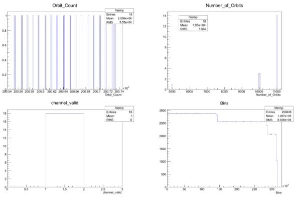
The output les are quite compact thanks to the TTree structure. The output le can be viewed us-ing the Root library. The TBrowser(A Browser from Root library) view of the output le can be found in the gure 4. In the TBrowser view all entries can be viewed.It should be know that the Bins plot which contains the UInt_t[14256] which stores the main data is not plotted correctly when browsed through TBrowser. In order for the data to be plotted correctly, this data has to be processed/opened by a Root macro or by a pro-gram similar to DataProcess. Examples on how TBrowser views these plots can be found at gure 5.
The data validation has been made and the pro-gram stores each data packet correctly and prop-erly. The program has been run for a time period of two days and it was still functioning without any problems. There shouldn't be any problems for longer periods of time. Currently this program is nalized and can safely used for data acquisi-tion. If more information on how to process the Fast/Slow Data stored by rhuRootStore is needed, you can contact me (Ismet Siral).
7 3 RHUDAQ DATA STORAGE SOFTWARE
Figure 5: rhuRootStore's output le's TBrowser view
3.3 PostMortemStore
PostMortemStore software package stores the Postmortem data whenever Postmortem data is available. The Postmortem data is not continuously streamed but instead it's only sent on a Beam Abort event. For this reason this software is completely dierent from the RhuRootStore software. This software doesn't need any running options/congurations.
3.3.1 PostMortemStore Data Structure
As referenced in section 2.2.4 Postmortem data structure is as follows:
1. 2 Fast Data Entries (Data Structure from Fast/Slow) (x8 for each Fast Channel) 2. TTimeStamp (Time Stamp)
3. bool (Valid/invalid signal)
4. unsigned char[50][14256/8] (Last 50 orbits BCM1F Data) (x8 for each Fast Channel) 5. unsigned long (Unique Orbit Numbers for last 50 orbits) (x8 for each Fast Channel) 6. bool (valid signal for last 50 orbits) (x8 for each Fast Channel)
The data stored in PostMortemStore is again stored in TTree Structures. There are 2 TTree structures per each channel. The rst TTree structure stores the 2 Fast Data Entries. The other TTree structure is used to store the BCM1F Data. There are eight TTree's (one for each fast channel). These TTree's contain three TBranch's. The rst two branches contain the unique orbit number and valid signal. The last TTree Branch is an unsigned char[14256/8] which stores the raw BCM1F data for a single orbit. The Array size for this data is 14256/8, the reason for this is each entry in BCM1F is a single bit while a PC can process a minimum of 8 bits / 1 byte. For this reason eight entries of BCM1F data is stored together in a single byte(char) to save up space.
3.3.2 Technical Details
The PostMortemStore program only creates an output le when there is a Postmortem Data available. The output le's names have the following format:
rhuPostData_<TimeStamp>.root (Example: rhuPostData_ 20120822T135840.235637.root). The soft-ware uses small amount of resources and can work independently of the RhuRootStore package. This
3 RHUDAQ DATA STORAGE SOFTWARE 8
allows the user to store the Postmortem data or not. Also the program being in dependent of RhuRoot-Store also prevents the data loss in fast and slow channel in case PostMortemRhuRoot-Store fails to work/crashes etc.
3.3.3 Output and Results
Currently the PostmortemStore hasn't been tested while the testing facilities are not available. Although when testing becomes available I (Ismet Siral) would be giving full software support for testing and main-taining the software.
3.4 DataProcess
DataProcess program is not a Data Storage program but it's a complimentary program for the previous rhuDataStore program. The DataProcess converts the input rhuDataStore output le into histograms, into a format that can easily be understood by the user. The program takes in a desired time interval to process and prints out all the histograms in the time interval to an output root le. All histograms are TH1I histograms and the extra information about all the histograms are written on the title of the histogram.
3.4.1 DataProcess Software Options
DataProcess has ve Software Options. The First Option is -h (help) which lists all other software options. The second option -s (start) sets the starting time of the period that the user wants to analyze. The Third option -e (end) set the end of the same time period. The Fourth option -f (folder) sets where the processed les are located. The Last option -r (sample) expects a sampling period (number of orbits that is accumulated on each histogram) and lters out all other les without that sampling period. (Example DataProcess run : ./DataProcess -s"2012-08-29 11:56:53.149329" -e"2012-08-30 11:56:53.149329" -r10790 )
3.4.2 Data Structure
Data structure of the DataProcess output le is kept as simple as possible. Each channel has its own directory and in this directory Histograms are listed according to their entry time. Each Histogram name is edited so that it contains the Time Stamp, Unique Orbit Number, Number of Orbits in that histogram and if the histogram is valid or not. This way the viewer of the histogram can easily analyze the data.
3.4.3 Technical Details
DataProcess is a fast program but it can use a lot of memory while it is running. It can use up to 200mb while it is opening and closing dierent les and writing reading. All though the program is being updated so that it uses less memory, currently the memory usage is inevitable. All though the memory usage won't be a big problem while this program is not designed for continuous running and when the program is terminated the memory usage no longer becomes an issue.
The program names it's output les in the format: output_ rhudata_ <Start Time >_ <End Time>.root (Example: output_ rhudata_ 20120821T124241.297885_ 20120823T130844.167463.root) The output le size is not constant because it is directly proportional by the time period that is asked to be created for. The size of the output le is generally % 15 more then the input le size. So the gure in section 3.2.3 can be used as a reference.
3.4.4 Output and Results
The output le of DataProcess is a huge le with lots of histograms. This has both pros and cons. The benet is that the user can easily view any time point he wants and can easily view them. The cons is that if the user species a long period of time, the amount of histograms generated can become thousands of histograms.
9 4 CONCLUSION
All histograms are currently stored properly without loosing any data. The created histograms also verify that rhuRootStore stores the data correctly. It can be veried that rhuRootStore stores the data properly because currently rhuRootStore stores simulated information and the bins(arrays) in the simu-lated information is a linear plot. When this information is stored and rhuRootStore and processed on DataProcess the following histograms are obtained. (See: gure 6).
Figure 6: Histograms created by DataProcess which takes a simulated information from rhuRootStore
As it is clearly visible the histogram plot is a linear graph which veries the storage and reading algorithm for rhuRootStore and DataProcess software packages. Also all extra information about the histograms are written in the title of the histogram. This prevents the system from loosing data while it's processing histograms.
4 Conclusion
The RHUDAQ Data Storage Software is currently completely functional.All functionality test are done for rhuDataStore and DataProcess packages and they have been proven to work. The next step is to do the tests with real hardware and after the tests the software should implemented it in to the RHUDAQ system. The PostMortemStore software is available but currently it has not been tested because Postmortem software simulation is not available. Testing of the Postmortem software will be done directly on hardware. The current software should be bug free but I (smet Sral) will continue to give full support to the software even after the Desy Summer Student program is over. Additional modules could easily be included if asked for.
Acknowledgements
I (Ismet Siral) want to Thank Wolfgang Lohman, Elena Castro and especially Marek Penno on their help for this project to become real. In addition I want to thank Igor Marn for the technical advice and comments. Also I want to thank all the DESY Sta and Community for giving me the chance to become a DESY Summer Student.
REFERENCES 10
References
[1] A. Bell, E. Castro, R. Hall-Wilton, W. Lange, W. Lohmann, A. Macpherson, M. Ohlerich, N. Ro-driguez, V. Ryjov, R.S. Schmidt, R.L. Stone, Fast Beam Conditions Monitor BCM1F for the CMS Experiment, arXiv:0911.2480v3
[2] R. S. Schmidt, A. J. Bell, E. Castro, R. Hall-Wilton, M. Hempel, W. Lange, W. Lohmann, S. Müller, V. Ryjov, D. Stickland, R. Walsh, Performance of the Fast Beam Conditions Monitor BCM1F of CMS in the rst running periods of LHC, arXiv:1012.3580v1
[3] Elena Castro,CMS: Bcm1Fdescription, https://znwiki3.ifh.de/CMS/Bcm1Fdescription (2012-02-10 16:40:15)
[4] Elena Castro, Beam Condition Data Analysis with BCM1F, FSP CMS Workshop
[5] Holger Leich, Marek Penno, Concept Draft for Recording Histogramming Unit, Desy CMS Group Internal Document (1/13/2012)
![Figure 1: Schematic of BCM1F Detector and it's installation location (Taken from [3] )](https://thumb-us.123doks.com/thumbv2/123dok_us/9045042.2393051/3.892.223.668.747.1005/figure-schematic-bcm-f-detector-installation-location-taken.webp)
![Figure 2: The arrival time distribution of particles crossing BCM1F sensors projected on the time of an orbit (Taken from [4])](https://thumb-us.123doks.com/thumbv2/123dok_us/9045042.2393051/4.892.224.670.485.652/figure-arrival-distribution-particles-crossing-sensors-projected-taken.webp)
![Figure 3: Abstract overview of the RHUDAQ System (Taken from [5])](https://thumb-us.123doks.com/thumbv2/123dok_us/9045042.2393051/5.892.167.725.327.603/figure-abstract-overview-rhudaq-taken.webp)