Design
Considerations
for Subsurface
Drip Irrigation
(SDI) Systems
Freddie R. LammResearch Irrigation Engineer Danny H. Rogers
Extension Agricultural Engineer Mahbub Alam
Extension Irrigation Specialist Gary A. Clark
Research Irrigation Engineer
Quick Facts
Subsurface drip irrigation (SDI) is a low-pressure irrigation system that uses polyethylene driplines that are permanently buried below the soil surface. Water drips to the surrounding soil through built-in emitters (specialized small open-ings). SDI places water directly into the root zone of the crop. It may improve yield due to high application uniformity and may have other production benefits, such as reduced weed and disease incidence.
SDI systems can have long life expectancy, but good design and maintenance are required. Clogging of dripline emitters is the primary reason for system failure.
SDI systems have high initial investment costs as compared to other Kansas irrigation system alternatives. However, cutting corners to save initial investment costs generally results in either poor system operation or reduced system longevity.
SDI systems have been success-fully operated since 1989 at Kansas State University Northwest Research-Extension Center. A number of studies have shown SDI to have various production advan-tages and potential for increased water conservation and water quality protection potential as compared to other common types of irrigation systems in the state. In some cases, these benefits will overcome the potential disadvan-tages, such as high initial cost. SDI systems must be carefully designed, operated, and maintained to ensure a long system life.
Proper design and management procedures must be used with SDI systems because water distribution problems may be difficult or impossible to correct if the system is improperly designed or poorly installed. Successful operation of an SDI system begins with a proper hydraulic design, which satisfies constraints dictated by crop and soil
characteristics; field size, shape, and topography; and water supply.
Disregard of design constraints will likely result in a system that is costly in both time and money and an increased chance of system failure. System failure could result in the loss of the total capital investment. Proper operation and maintenance also are important for satisfactory performance and system longevity.
In this publication, SDI design considerations will be discussed. Operation and management consid-erations for SDI systems are discussed in the publication SDI Management Considerations, MF-2590. Filters and filtration for SDI systems are discussed in Filtration and Maintenance Con-siderations for Subsurface Drip Irrigation (SDI) Systems, MF-2361. A general description of SDI system components appears in Subsurface Irrigation (SDI) Components: Minimum Requirements, MF-2576. Water quality issues are discussed in MF-2575, Subsurface Drip Irrigation (SDI) Water Quality Assessment Guidelines.
This publication is not intended to be a step-by-step design proce-dure, but rather a review of design concepts that will help a producer who is considering SDI as an irrigation system. It should help producers understand principles of a successful system and allow them to ask and discuss appropri-ate questions with the designer or seller of SDI components.
Irrigation Capacity
A major advantage of a well designed and operated SDI system is its ability to apply water with high uniformity and efficiency. Improvement in system efficiency may help reduce the total seasonal irrigation diversion. However, the net irrigation capacity requirement to meet the crop water need during peak water demands of the major crops grown in Kansas, remains Kansas State University
Agricultural Experiment Station and Cooperative Extension Service Manhattan, Kansas
the same, regardless of system efficiency. In high water-holding-capacity soils such as loams and silt or clay loams, a net irrigation capacity of 0.25 inches per day is sufficient to meet evapotranspira-tion (ET) demand for most of the growing period and prevent water-limiting yield stress with a greater than 90 percent reliability. This would be considered full irrigation capacity. ET demand in excess of irrigation capacity during the growing season is met from soil water storage reserves.
The general recommendation is that SDI systems be designed to provide full irrigation. Producers who have SDI systems with less than full irrigation capacity, must adjust their management strategies to recognize the increased risk.
The desired irrigation capacity, combined with the well’s discharge capacity, determines the number of acres that can be irrigated. Al-though SDI systems are not perfectly uniform or efficient, a good goal should be greater than 90 percent uniformity. Because irrigation efficiency can be defined as water used beneficially divided by the water delivered to the field, a well-designed and operated SDI system can be nearly 100 percent efficient. However, when the uniformity is considered, overall irrigation efficiency will be somewhat less. Uniformity varia-tions along the length of the dripline will be discussed in a later section. For the moment, assume the overall irrigation efficiency of the system is 95 percent. If a desired net irrigation capacity for a potential SDI field is 0.25 inches per day, then the gross irrigation capacity requirement is 0.25 ÷ 0.95, or 0.26 inches per day.
The number of acres that can be irrigated for a given well discharge and irrigation capacity can be calculated as shown in Example 1.
Therefore, an 800 gpm-well would be adequate to irrigate an
entire quarter section at the given irrigation capacity. Loam or silty clay loam soils have a buffering capacity due to high water-holding capacity to meet ET requirements on days when ET exceeds design capacity of 0.25 inches per day.
The water-holding capacity of sandy soils is low and lacks suffi-cient storage to buffer high demand. Thus, sandy soils require a higher irrigation capacity — in the range of 0.32 inches per day in Kansas for corn production — in order to ensure full irrigation capacity. The irrigation application depth must match the water-holding capacity of the soil to avoid deep percolation. Irrigation on sandy soils is gener-ally more frequent with less water applied during each irrigation event.
Zone Size
and Dripline Spacing
Irrigation capacity defines the daily average depth of water that could be applied to an entire field. However, as with any other system, SDI usually only applies water to a portion of the field at a given time. The portion of the field that is watered at the same time is generally called a zone. The zone size for an SDI system isdeter-mined by the operating characteris-tics of the dripline selected (emit-ter discharge rate and spacing, dripline spacing, and operating pressure) and the discharge rate of the well. The zone size is some-what analogous to the set size for gated pipe surface irrigation because each furrow needs a certain flow for water to advance properly. For SDI, the dripline also needs a certain flow in order to operate properly.
The amount of dripline needed per acre is determined by the line spacing. SDI research conducted on silt loam soils at K-State Research and Extension Centers in Colby and Garden City indicated a 5-foot spacing of dripline was optimal for 30-inch row corn production. The amount of dripline needed per acre is determined by dividing the square footage per acre by the dripline spacing. For a 5-foot spacing, the dripline needed for each acre is shown in Example 2.
Driplines are characterized in a variety of ways, but common methods are to indicate the flow in gpm per 100 feet or gph per emitter. The emitters can either be manufactured as part of the Example 1. Well discharge and irrigation capacity
Acres irrigated = GPM × Hrs 450 × IC Gross
Where GPM = water discharge rate in gpm
* Conversion factor: 450 gpm = 1 acre-inch per hour * Hrs = Number of hours of operation per day IC gross = Gross Irrigation Capacity in inches/day
An example: How many acres can a well with an 800 gpm discharge rate irrigate at the irrigation capacity requirement of 0.26 in/day?
Acres irrigated = 800 × 24 = 164 acres 450 × 0.26
Example 2. Dripline needed per acre
Dripline (feet per acre) = 43,560 ft/ac = 45,560 ft/ac = 8,712 ft/acre Dripline spacing (ft) 5 ft
dripline or inserted during the manufacturing process. Driplines with lower flow rate per emitter may fall in the range of about 0.10 gph per emitter, or 0.17 gpm per 100 feet of dripline length. Com-mon emitter spacing is 12 to 24 inches apart and operated at a pressure of 8 to 12 psi. In agricul-tural settings, driplines with a flow rate of 0.2 to 0.25 gpm per 100 feet of length are commonly used. Low flow driplines are desirable in agricultural settings to increase the zone size. This reduces the number of valves and fittings required to install the system. This is generally the most cost effective design option.
Every design is site specific and may have unique characteris-tics or requirements. Driplines with flow rates many times higher than these values are available and may be used to fit specific needs.
The flow rate needed per acre for 5-foot spacing with driplines rated at 0.25 gpm per 100 feet is shown in Example 3.
The size of the zone is then determined by dividing the rated well capacity by the predetermined dripline capacity. Assuming a well capacity of 870 gpm, the zone size is shown in Example 4.
A 40 acre zone size would be a convenient zone size for the traditional quarter section. Also, it was previously determined that 800 gpm would be sufficient to
meet full irrigation requirement for a quarter section. Thus, the system would require four 40 acre zones.
If only 600 gpm were available, then the zone size would be about 27 acres with six zones required to cover the field. However, the gross irrigation capacity of the system would be only 0.2 inches per day with a 600 gpm water supply. Producers may chose not to install all zones if they feel this capacity results in too much risk.
The dripline spacing is obvi-ously an important factor in system cost because wider spacing reduces initial investment cost. However, wide spacing may not spread the water uniformly to supply crop water needs. It will likely result in excess deep percolation along the dripline in many soil types in an effort to wet the space between driplines. The dripline spacing is dictated by the lateral extent of the crop root zone, lateral soil water redistribution, and in-season precipitation. While studies on silt loam soils in western Kansas conducted by Kansas State Univer-sity indicated that a 60-inch dripline spacing is optimal for a corn-row spacing of 30 inches, it may be feasible and logical to use a 72-inch dripline spacing for corn planted in 36-inch rows. However, this might limit successful use of the system for crops grown in a narrow row pattern. A 72-inch dripline spacing is not recom-mended in the Central Great Plains
for corn grown in 30-inch rows, even though some dripline install-ers may recommend this as a way to cut investment costs. On the other hand, it may be necessary to reduce spacing for soils that are sandy or light textured.
Soils that have a restrictive clay layer below the dripline installa-tion depth might be able to use a wider dripline spacing without affecting crop yield. Wider spac-ings also may be considered in areas of increased precipitation, since crop dependency on irriga-tion is decreased.
The choice of emitter spacing is dictated by soil characteristics, plant spacing, and water quality. Wider spacing of emitters on the dripline allows a larger emitter opening that may perform better where water quality is less than optimal. However, emitter spacing is usually less than the dripline spacing, and most emitters are spaced between 12 and 24 inches. As a rule of thumb, dripline spacing is related to crop row spacing, while emitter spacing is more closely related to soils and plant spacing within the row. One of the inherent advantages of an SDI system is the ability to irrigate only a fraction of the crop root zone. Careful attention to dripline spacing and emitter spacing are key factors for water conservation and water quality protection.
Dripline
Installation Depth
Installation depth is also related to the crop and soil type. Deep installations reduce the potential for soil evaporation and allow for a wider range of tillage practices. There may also be some reduced potential for chemical, biological, and root clogging of the emitters with deeper installations, which also may be less susceptible to rodent damage. However, deep installations limit the effectiveness of the SDI system for germination Example 3. Flow rate per acre
Flow rate/acre = Dripline rating (gpm/100 ft) × feet of dripline per acre = 0.25 gpm × 8,712 ft = 21.8 gpm
100 ft acre acre
Example 4. Zone size
Zone size (acres) = Well capacity (gpm) = 870 gpm = 39.9 acres Dripline flowrate (gpm) per acre 21.8 gpm/acre
and may restrict availability of surface-applied nutrients. Accept-able crop results have been ob-tained with dripline depths of 16 to 18 inches in K-State studies in western Kansas on deep silt loam soils. Some producers in the Central Great Plains region are opting for installations in the 12- to 14-inch depth range to give more flexibility in germination. How-ever, it is difficult to get water for germination with SDI systems. Shallow installations expose the driplines to more hazards from farming operations and rodents.
The dripline should probably be installed above any restrictive clay layers that might exist in the soil. This would help increase lateral soil water redistribution.
Subsurface drip irrigation (SDI) technologies have been a part of irrigated agriculture since the 1960s, but have advanced at a more rapid pace during the last 20 years (Camp et al. 2000). In some areas, SDI has not been readily accepted because of problems with root intrusion, emitter clogging, and lack of visual indicators of the wetting pattern. In high-value crops, these indeed can be valid reasons to avoid SDI. However, in the Central Great Plains, with relatively low-value commodity crops such as corn, only long term SDI systems, where installation and investment costs can be amortized over many years, have any realistic chance of being economically justified. Kansas irrigators are beginning to try SDI on their own. There has been a lack of research-based information on appropriate depth for driplines. Camp (1998) reviewed a number of SDI studies concerning depth of installation and concluded the results are often region specific and optimized for a particular crop.
A study was initiated at the KSU Northwest Research-Exten-sion Center at Colby, Kansas in
1999 to evaluate the effect of dripline depth on corn production and SDI system integrity and longevity. The effects of five dripline depths (8, 12, 16, 20, and 24 inches) on SDI system longev-ity and corn production will be determined. System longevity will be evaluated by monitoring individual flow rates and pressures at the end of each cropping season to estimate system degradation (clogging) with time. There was no appreciable or consistent effect on corn grain yields during the period 1999-2002. However, it is still too early to answer questions about how depth affects longevity (chemical and biological clogging, pests, and tillage practices). The study area has not been used to examine the effects of dripline depth on germination in the spring, but studies in this regard may be conducted in the future. Damp surface soils are sometimes observed for the 8 and 12 inch dripline depths during the irriga-tion season, but not for the deeper depths. There is a tendency to have slightly more late season grasses for the shallower 8 and 12 inch depths, but the level of grass competition with the corn is not great. The dripline depth study is managed with the modified ridge-till system (5-foot bed) as shown in Figure 1. Cultivation for weeds in early summer has been routinely practiced and there have been no instances thus far of tillage tool damage to the shallow 8-inch depth driplines.
The orientation of driplines with respect to crop rows has not been a critical issue with SDI systems used for corn production on deep-silt loam soils. Tradition-ally, driplines are spaced parallel to crop rows. This may be advan-tageous in planning long-term tillage, water, nutrient, and salinity management. However, K-State research has shown either parallel or perpendicular
orienta-tions are acceptable for the 5-foot spacing on deep silt loam soils.
Flushing Requirements
All SDI systems should have a flushing arrangement that should be considered during the design phase. In simple terms, the flow velocity of the water in the dripline and flushline must be high enough to remove any sediment that might accumulate. Manufacturers’ recommendations should be followed. One diffi-culty is that the larger diameter driplines generally have flushing velocities that are greater than those for smaller diameter driplines. Flushing of smaller diameter driplines often can be accomplished by increasing the speed of the existing pumping plant if the well can provide additional flow for the flush period. If the well discharge rate is not sufficient, then the
flushline serving a zone may need to be split in half during design to accommodate flushing.
A flushing system is recom-mended at the distal end of the dripline laterals to help remove sediment and other materials that may accumulate during the season. Additionally, the SDI systems needs a proper filtration system. A useful way to provide Figure 1. Dripline placement relative to corn rows in studies at the North-west Research and Extension Center, Colby, Kansas.
for flushing is to connect all the distal ends of the driplines in a zone to a common submain or header that is called the flushline. This allows the flushing to be accomplished at one point. Two other distinct advantages exist for this method. If a dripline becomes clogged or partially clogged, water can be provided below the clog by the interconnected flushline. Additionally, if a dripline breaks, positive water pressure on both sides of the break will limit sediment intrusion into the line.
Generally, a minimum flow velocity of 1 to 2 feet per second is considered adequate for flushing dripline laterals. This flow velocity requires careful sizing of the mains, submains, flushline mains, and valves. Without a proper flushing system design and regular maintenance, most SDI installa-tions will become fully or partially clogged, thus, limiting crop yield and reducing system life.
Field Size, Shape,
and Topography
SDI systems can be success-fully used on a variety of fields. The most limiting characteristic is field slope, especially undulating or variable multidirectional sloped fields. In general, surface furrow irrigated fields can be irrigated by an SDI system with few design difficulties.
While the overall field size may be limited by the available water supply, SDI has the ability to economically adjust the size of the irrigated field to the available water supply. This is a distinct advantage of SDI systems com-pared to center-pivot sprinklers. If sufficient water is available, the field size, shape, and topography, along with the dripline hydraulic characteristics, will dictate the number of zones. Minimizing the number of necessary zones will
result in a more economical system to install and operate.
Whenever possible, dripline laterals should be installed downslope on slopes of less than 2 percent. On steeper terrain, the driplines should be placed along the field contour and/or techniques for pressure control should be used. In a following section on dripline hydraulic characteristics, the effects of slope and dripline diameter and length will be discussed in detail.
Irrigation
Application Depth
The application depth of water and the length of application are directly related. Generally, SDI allows efficient high frequency and low volume applications of water. For fully automated systems, this means the entire field could be irrigated daily. On a more practical level, for manually operated systems, 12-hour irrigation times fit daily labor requirements much better. The application depth is calculated in Example 5.Filtration, Flushing,
and Water Treatment
Clogging of the dripline emit-ters is the major cause of system failure. Clogging can be caused by physical, chemical, or biological materials. The filtration system is one of the most important compo-nents of the SDI system.
In selecting a filtration system, consider water quality and emitter size. Improper filter selection can result in a system that is difficult to maintain and prone to failure. Operational and maintenance requirements of the filter must be well understood by the irrigator to help ensure system longevity. The filtration system can be automated to flush at regular intervals or at a set pressure differential across the filter. A more complete K-State source on this topic is MF-2361, Filtration and Maintenance Considerations for Subsurface Drip Irrigation (SDI) Systems. Screen, disk or sand media filters are used to remove sus-pended solids such as silt, sand, and organic and inorganic debris. While filtration is required for all water sources, surface water often requires more extensive filtration than groundwater.
Chemical reactions in the water can cause precipitates, such as iron or calcium deposits, to form inside the driplines or emitters. Clogging can be caused by either natural water conditions or by chemicals, such as fertilizer, added to the water. To avoid chemical clogging, the water must be analyzed to determine what chemicals are prevalent and which chemical additives should be avoided. Chemical water treatment may be required continuously or intermit-tently. Acids are sometimes used to
Example 5. Gross Application depth*
Gross Irrigation Application Depth = GPM × Hrs Irrigated ÷ Acres irrigated per zone 450
For the 871-gpm well on 40-acre zones, a 12-hour irrigation cycle would apply:
Gross Irrigation Application Depth =
871 gpm × 12 hrs ÷ 40 acres/set = 0.58 inches/zone 450 gpm/ac-in/hr
prevent plugging and help renovate partially plugged driplines. The need for treatment is dictated by the water source and emitter size. A thorough chemical analysis of the water source should be made before developing the SDI system.
Biological clogging problems may consist of slimes and algae. Some problems are eliminated in the filtration process, but inject-ing chlorine into the driplines on a continuous or periodic basis is required to stop the biological activity. The water source and composition will determine, to a large extent, the need for chlori-nation.
Water Testing
Water quality testing is an important consideration, and results should be known before designing an SDI system. Poor quality water can be successfully used in SDI, but only with proper filtration and/or treatment. The driplines also may require addi-tional or more frequent cleaning to prevent clogging. Water quality issues for SDI systems are dis-cussed in publication MF-2575, SDI Water Quality Assessment Guidelines.
Dripline Hydraulic
Characteristics
As previously discussed, SDI systems can be highly efficient and apply water in a very uniform manner. This section will discuss some of the fundamental hydraulic concepts that designs must con-sider for high efficiency and reliability.
Pressure losses from friction occur when water flows through a pipe. These friction losses are related to the velocity of water in the pipe, the pipe inside diameter and roughness, and the overall
length. The emitter flowrate (Q) can generally be characterized by a simple power equation:
Q = k Hx
Where k is a constant depending upon the units of Q and H. H is the pressure at emitter and x is the emitter exponent. The value of x is typically between 0 and 1. When x equals 0, the flowrate of the emitter is independent of the pressure. This would allow for high uniformity on very long driplines, which would minimize cost. Any product with an emitter exponent x equal to 0 is said to be fully pressure compensating. An x value of 1 is noncompensating, meaning any percentage change in pressure results in an equal per-centage change in flowrate. Most dripline products typically used in agricultural settings have an emitter exponent of approximately 0.5. A 20 percent change in pressure along the dripline would result in a 10 percent change in flowrate if the exponent is 0.5. As a rule of thumb, flowrates should not change more than 10 percent along the dripline in a properly designed system. Most manufac-turers can provide the emitter exponent for their product.
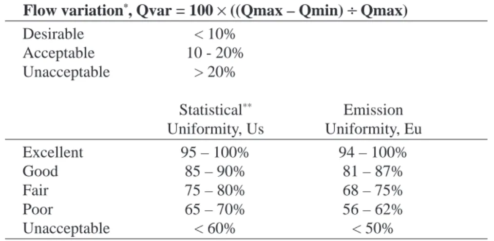
Irriga-Table 1. Various Uniformity Criteria
Flow variation*, Qvar = 100 × ((Qmax – Qmin) ÷ Qmax)
Desirable < 10% Acceptable 10 - 20% Unacceptable > 20% Statistical** Emission Uniformity, Us Uniformity, Eu Excellent 95 – 100% 94 – 100% Good 85 – 90% 81 – 87% Fair 75 – 80% 68 – 75% Poor 65 – 70% 56 – 62% Unacceptable < 60% < 50% * Bralts, et al., 1987 ** ASAE EP-458 400 ft run 600 ft run 800 ft run 10% Flow variation 0.25 0.20 0.15 0 100 200 300 400 500 600 700 800
Dripline Lateral Length (ft)
Flowrate (gpm/100 ft)
Figure 2. Calculated dripline flowrates on level slopes as affected by length of run. For this example small-diameter (5/
8 inch) dripline, only the 400 foot lateral length
Figure 3. Calculated flowrates on level slopes as affected by dripline capacity. In this small-diameter dripline example only the 0.25 gpm/100 ft dripline capacity meets the desired criteria of maintaining flow variations less than 10 percent.
.25 gpm/100 ft .50 gpm/100 ft .75 gpm/100 ft 10% Flow variation 1.0 0.9 0.6 0.7 0.8 0 100 200 300 400
Dripline Lateral Length (ft)
Flowrate (% of design)
tors should compare the emitter exponent among products and be wary of manufacturers that cannot provide this information.
Friction losses increase with length (Figure 2). For this ex-ample, the small-diameter dripline has a design flowrate of 0.25 gpm per 100 feet at 10 psi on a level slope. The variations in flows, Qvar, are 6, 16, and 29 percent for the 400, 600, and 800-foot runs, respectively. Using general criteria for Qvar, these systems would be classified as desirable, acceptable, and not acceptable (Table 1). This example is based on 5/
8-inch
diameter dripline. Longer lengths of run are possible with larger diameter dripline. The industry has responded well to the needs of the farmer, and larger diameter driplines are available. However, producers are encouraged to compare investment and antici-pated management costs for the various dripline sizes before deciding what is the optimal dripline size for their installation. Dripline diameters slightly larger than one inch (13/
8 inch) are being
used for 1/2-mile-long runs in full,
quarter, and half sections. Larger diameters are not always more desirable, as they require longer
filling and flushing times. This could affect water and chemical application uniformity.
Friction losses also increase with increased velocity of water in the dripline. For a given inside diameter of line, friction losses will be greater for driplines with higher flowrates (Figure 3). Some designers prefer higher capacity driplines because they are less subject to clogging and allow more flexibility in scheduling irrigation.
However, if larger-capacity driplines are chosen, the length of run may need to be reduced to maintain good uniformity. Addi-tionally, the zone size may need to be reduced to keep the flowrate within the constraints of the water supply. Decreasing the length of run or the zone size increases the cost of installation and operation. The land slope can have a positive or negative effect on the pressure distribution along the dripline lateral (Figure 4). Irrigating uphill will always increase pressure losses along the lateral length. If the downhill slope is too large, the flowrate at the end of the line may be unacceptably high. In the example shown, the optimum slope is either 0.5 or 1.0 percent downslope. Both slopes result in a flowrate variation of approxi-mately 10 percent for the 600-foot run. If slopes are too great, there is the opportunity to run the driplines cross-slope or along the contour. Pressure compensating emitters also can be used on greater slopes, but may not be cost competitive for relatively low-value crops such as corn.
The preceding discussion has dealt with theoretical calculations that do not take into account the
Figure 4. Calculated dripline flowrates as affected by slope. In this small-diameter dripline example, the 0.5 and 1.0 percent downslope dripline laterals meet the desired criteria of maintaining flow variations less than 10 percent.
0.30
0.25
0.15 0.20
0 100 200 300 400 500 600
Dripline Lateral Length (ft)
Flowrate (gpm/100 ft)
Acceptable 10% flow variation between solid black lines
0.5% Up 1.0% Up 0.5% Dn Level 2.0% Dn 1.0% Dn
Acknowledgment: This material is based upon work supported by the U.S. Department of Agriculture Cooperative State Research Service under Agreement No. 00-34296-9154. Any opinions, findings, conclusions or
recommendations expressed in this publication are those of the authors and do no necessarily reflect the views of the U.S. Department of Agriculture.
Brand names appearing in this publication are for product identification purposes only. No endorsement is intended, nor is criticism implied of similar products not mentioned.
Publications from Kansas State University are available on the World Wide Web at: www.oznet.ksu.edu
Contents of this publication may be freely reproduced for educational purposes. All other rights reserved. In each case credit, Freddie R. Lamm et al., Design Considerations for Subsurface Drip Irrigation (SDI) Systems, Kansas State University, July 2003.
Kansas State University Agricultural Experiment Station and Cooperative Extension Service
MF-2578 July 2003
It is the policy of Kansas State University Agricultural Experiment Station and Cooperative Extension Service that all persons shall have equal opportunity and access to its educational programs, services, activities, and materials without regard to race, color, religion, national origin, sex, age or disability. Kansas State University is an equal opportunity organization. Issued in furtherance of Cooperative Extension Work, Acts of May 8 and June 30, 1914, as amended. Kansas State University, County Extension Councils, Extension Districts, and United States Department of Agriculture Cooperating, Marc A. Johnson, Director.
variability in manufacturing. The coefficient of manufacturing variation, Cv, is a statistical term used to describe this variation. Some dripline products are inher-ently difficult to manufacture with consistency and, therefore, may have a high Cv. Other products may suffer from poor quality control. The American Society of Agricultural Engineers (ASAE) has established Cv ranges for line-source driplines. A Cv of less than 10 percent is considered good; from 10 to 20 percent, average; and greater than 20 percent, marginal to unacceptable. The Cv of a product should be obtained from the manufacturer to aid in decisions regarding suitability of the product for a particular instal-lation.
Concluding Statement
The initial investment costs for an SDI system are high. Efforts are justified to minimize investment costs whenever possible and practical. However, if water conser-vation and water quality protection are important, proper design procedures must be used. The SDI system must be properly designed to ensure system longevity. Mini-mizing investment costs throughcheaper designs can be a double-edged sword, as a cheaper system may increase operating costs and/or the chance of system failure.
K-State continues to develop appropriate methodology for successful utilization of SDI technology in the Central Great Plains. Much of this technology is summarized on the K-State SDI Web site, which can be accessed at: www.oznet.ksu.edu/sdi/
References
American Society of Agricul-tural Engineers (ASAE). 1994 Field Evaluation of
Micro-irrigation Systems. ASAE EP-458, Dec 1193, pp 760-765
Bralts. V.F., D.M. Edwards, and I.P. Wu. 1987. Drip Irrigation and Design and Evaluation Based on the Statistical Uniformity Concept. Advances in Irrigation. 4:67-117.
Camp, C. R., F. R. Lamm, R. G. Evans and C. J. Phene. 2000. Subsurface drip irrigation - Past, present and future. In Proc. Fourth Decennial Nat’l Irrigation Symp., Nov. 14-16, 2000, Phoenix, AZ. Sponsored by ASAE. pp. 363-372.
Camp, C.R. 1998. Subsurface drip irrigation: A review. Trans ASAE 41(5):1353-1367.
Additional Resources:
MF-2242, Economic Compari-son of SDI and Center Pivots for Various Field SizesMF-2361, Filtration and Main-tenance Considerations for Subsur-face Drip Irrigation (SDI) Systems
MF-836, Irrigation Capital Requirements and Energy Cost
MF-2590, Management Consid-eration for Operating a Subsurface Drip Irrigation System
MF-2576, Subsurface Drip Irrigation (SDI) Components: Minimum Requirements
MF-2575, Subsurface Drip Irrigation (SDI) Systems Water Quality Assessment Guidelines Related K-State Research and Extension SDI Irrigation Web sites:
General Irrigation
www.oznet.ksu.edu/irrigate Mobile Irrigation Lab www.oznet.ksu.edu/mil Subsurface Drip Irrigation www.oznet.ksu.edu/sdi