*Correspondence to Author:
S.O. Osuji
University of Benin Department of Civil Engineering Benin City, Edo State, Nigeria.
How to cite this article:
S.O. Osuji, L.O. Adhekoyibo. Com-parative Analysis of Collapse Loads of Slabs Supported on Orthogonal Sided Frames with Beam/ Column Joint Fixed . American Journal of Engineering Research and Re-views, 2018, 1:7
eSciPub LLC, Houston, TX USA. Website: http://escipub.com/
S.O. Osuji, L.O. Adhekoyibo, AJOERR, 2018, 1:7
American Journal of Engineering Research and Reviews
(ISS
N
:2
6
37
-
378
5
)
Research Article AJOERR (2018) 1:7
Comparative Analysis of Collapse Loads of Slabs Supported on
Orthogonal Sided Frames with Beam/ Column Joint Fixed
This research work evaluates the collapse loads of slab sup-ported on orthogonal side ended frames with column/beam joint fixed. Two frame models were investigated (one with Moment of Resistance of slab (MRS) > Moment of Resistance of beam (MRB) and the other with Moment of Resistance of slab (MRS) < Moment of Resistance of beam (MRB)). A reinforced concrete prototype of 3m*3m*3m frame with a reduction factor of 3 was designed and constructed. A model of it constructed and cast with a micro concrete of 1:6 mix ratio. The models were allowed to cure for 28days before being loaded directly until collapse. The estimated collapse load for slab and beam were 20.36KN/ m and 52.27KN/m respectively. The actual collapse loads of the frame models (MRS > MRB and MRS < MRB) were 69.04KN/
m and 49.68KN/m respectively. The frame model failed by flex -ural failure at the beams /column joints. The actual collapse load of 69.92KN and 49.68KN respectively were greater than that of the estimated collapse loads of beam and slab comparably. Also the MRS > MRB frame model is stronger than that of the MRS < MRB frame model.
Keywords: Moment of resistance force, collapse load, slap, beam
S.O. Osuji, L.O. Adhekoyibo
University of Benin Department of Civil Engineering Benin City, Edo State, Nigeria.
ABSTRACT
AJOERR: http://escipub.com/american-journal-of-engineering-research-and-reviews/ 1
Introduction
Frame structure is a combination of beams, columns, slabs and footings rigidly connected together to form a monolithic entity. Each individual member must be capable of resisting the forces acting on it; hence, the determination of these forces is an essential part of the design process (Mosley and Bungey, 1993).
Also, structural frames can be said to be composed of one-dimensional members connected together in skeletal arrangements which transfer the applied loads to the supports. While most frames are three-dimensional, they may often be considered as a series of parallel two-dimensional (plane) frames, or as two perpendicular series of two-dimensional (plane) frames (Trahair, Bradford and Nethercot, 2001). The behavior of a structural frame depends on its arrangement and loading, and on the type of connections.
With three dimensional structures, even with quite small structures, there can be a large number of joints each with six degrees of freedom. Therefore, the number of simultaneous equations to be formed and solved is six times the number of joints (6j), which leads to very expensive computer runs in order to get a solution for the whole structure. Hence, it is usual to adopt some form of simplification to reduce the tediousness.
Framed reinforced concrete structures, which are to be constructed in-situ, are normally designed and detailed (as in figure 1a) so as to be able to transfer moments and shear forces at beam-column joints. However, it very common to see such detailing as in figure 1b on site, where no bent bars is provided for effective transfer of moments and shear forces at the beam-column joint. This type of joint such as in figure 1b, will behave as a hinged joint, since it has no capacity to transfer moment; while that of joint such as in figure 1a will behave as a fixed joint [Priestley, 1997, Hakuto et al, 1999]
Fig. 1a: Reinforcement detailing at Column joints
Fig. 1b: Reinforcement detailing at Column joints
PROBLEM OF RESEARCH STATEMENTS
The poor detailing of reinforced concrete frame structures, especially at the beam/column joint is one of the major problems facing the Nigeria industry today. This problem is due to a lot of factors such as poor workmanship, usage of unskilled workers and poor supervision.
Researches into the behavior and mode of failure of beam where extensively carried out; however, researched into the behavior and mode of failure of space frame reinforced concrete structures with beam/column joint fixed is rare. Hence, the secondary focus of this research work is to investigate the effect of good detailing work on the load capacity of frame structures.
RESEARCH SIGNIFICANCE
In the convectional design reinforced concrete using limit state method according to BS8110 (2001), the component structural elements are
S.O. Osuji, L.O. Adhekoyibo, AJOERR, 2018, 1:7
design independently of others. The issue of moment redistribution if at all considered is confined within the limit structural element along the plane being considered. Although, this approach may be safe if it is a conservative one this inherently contradicts the aim of designing a safe structure at the least possible cost.
AIM AND OBJECTIVES
The aim of this research work is to evaluate the collapse loads of slabs supported on orthogonal sided frame models: firstly, one with MRS greater than MRB, and secondly one with MRS less than MRB with fixed joint.
The primary objective of this study is to:
i. To determine the collapse load of the two frames: firstly, one with MRS greater than MRB, and secondly one with MRS less than MRB.
ii. To understand the mode of collapse of the two frame model.
iii. To gain experimental evidence of the mode of collapse of the frame model. iv. To gain analytical evidence of the
collapse load of the frame model.
The recent collapse of buildings in the country calls for the investigation of not only the collapsed buildings, but the behavior of the materials used for the construction of the buildings collapsed building under load. One of the ways of doing this is to carryout load test on models constructed from the same building materials used for the construction of the failed structures. In the present day construction industry in Nigeria, concrete has emerged as the most common building material. It is also worth noting that over eighty percent of the collapsed building in Nigeria as today is constructed from reinforced concrete. Hence careful consideration must be given to factors that affect the strength of reinforced concrete (Olanitori, 2005).
In his report, Adeoye (PGD 1998) noted that between December 1976 and January 1995, over 30 cases of collapse of buildings were
reported across the country, with well over 250 person lost their lives with several others severely injured. Also Amanda-Ayafa (PGD 2000), noted that between May 1987 and April 2000, over 22 cases of building failure were reported in Lagos State. Also between January 2005 and August 2006, over 8 cases of building collapse were recorded in the country (Olanitori, 2005).
Akintola, Fakorede, and Osuntade (2009), in their load tests of 1m square single panel space frame hinged joint models (MRS greater than MRB), with slab thickness equals 50mm, beam cross- sectional dimensions are 75mm by
100mm, and column cross-sectional
dimensions are mm by 75mm, the collapse load was 37.4KN, while the maximum deflections at collapse are 5.7 and 5.9mm for beam and slab respectively. Investigating the same type of reinforced concrete models, Akinya, Babatope and Dominic (PGD 2009), determine the load to be 26.4KN, while deflections are 3.35mm and 7.56mm for beam and slab respectively. Also, Famoye, Majekodunmi and Olaleye (PGD 2010), determine the collapse load for the same type reinforced concrete model as 21.96KN, while the deflections are 5.85mm and 22.33mm for beam and slab respectively. In all the three cases cited above, the mode of collapse is by shear failure at the beam/column joints. This is due to the fact that the moment of resistance of slab (MRs) is greater than moment of resistance of beam (MRS), hence slab transfer directly the load to the column, instead of from slab to beam and beam to column (Famoye, A.A, Majekodunmi, A.S and Olaleye,O.T. 2010).
Standard Collapse Mechanism and Collapse Loads
Four standard cases of collapse mechanism for slab with edge beams as given by Moy [1981],
is as shown in figs. 2.3.1a-d. The type of collapse mechanism for a particular slab depends on the relative moments of resistance of the beams and slab.
(a)
(b) (c) (d)
Fig. 2.3.1a-d: standard collapse mechanisms for square slabs (Moy 1981)
Collapse mechanism a: the edge beams are so strong that the diagonal mechanism forms in the slab. Only positive yield lines are required because he beams can rotate after torsion failure in the corners. For this type of collapse mechanism, the collapse load can be estimated from
n= 24M/L2
Collapse mechanism b: this type of mechanism depends on Mb/ML, which is a measure of the relative magnitudes of the moments of resistance of the edge beams and slab. The collapse load for this type of mechanism can be calculated using
n = 8M/L2(1+2Mb/ML)
Collapse mechanism c: also this type of mechanism depends on Mb/ML, which is a measure of the relative magnitudes of the moments of resistance of the edge beams and slab. The collapse load for this type of mechanism can be estimated as for collapse mechanism b.
Collapse mechanism d: this type of mechanism can occur when one of the edge beams is weaker than the others, and collapse load can be estimated from
𝑛 =8𝑀
𝐿
(1 +𝑀𝑏𝑀𝐿 +4𝑋)𝐿
𝐿 −𝑋3
M = the moment of resistance of the slab,
L = the length of the slab,
Mb = the moment of resistance of the beam
MATERIAL AND METHOD
The materials used for this research work includes two RC frame models, constructed using micro concrete (i.e cement and sand in ratio 1:6) and reinforcements. Steel
reinforcement characteristics strength of 250N/mm2 was used. The cement and sand with adequate water was thoroughly mixed and gently poured into the formwork provided for the model starting from foundation to columns, then later to beams and slab. The RC model shall be allowed to set, harden and cure for 28days after which it was ready for loading.
After 28 days when the concrete had gained maximum strength, the RC frame model was loaded by putting a loading box with dimensions 1m* 1m* 3.0m on top of the slab of the frame. Two dial gauges was used, one was set at the centre of the bottom of the slab while the other was set below the edge beams to monitor, measure centre and edge deflections. The dial gauges was adjusted to zero before taking reading. Reading of the dial gauges was taken at every 10 head pans (1.84KN) of sand into the loading box.
1000
1000
75
50
3D description of the model with dimensions
DESIGN CONCEPT
The frame was analyzed and design in accordance to BS8110
ESTIMATION OF COLLAPSE LOAD OF THE FRAME
Using Moment of Resistance of Slab
S.O. Osuji, L.O. Adhekoyibo, AJOERR, 2018, 1:7
Fcc = Fst
0.45×Fcu×b×s = 0.87×fy×Asprov
0.45×7×1000×s = 0.87×250×142
S = 0.87×250×1420.45×7×1000 = 9.80mm
X = 𝑆 0.9 =
9.80
0.9 = 10.89mm
Hence the steel has yielded since 10.89 < 0.615d = 0.615×41 = 25.23mm
Ms = 0.87fyAs (d-s/2)
= 0.87×250×142× (41-9.80/2) ×10-6 = 1.12KNm
Hence Ms = Mu
Where Ms = Moment of resistance of the slab
Mu = is the Ultimate Moment.
The above equation can be written in a compressed form as stated in BS8110 part 1, we have:
M = αnLx2
From table 3.14 of the BS8110 part 1, α = 0.055
Where Lx = length of the shorter span of slab = 1000mm
n = estimated collapse lord
1.12 = 0.055×n×12
n = 1.12/0.055 = 20.36KN/m
Hence the estimated collapse lord for Slab is 20.36KN/m
Using Moment of Resistance of Beam
Fcc = Fst
0.45fcubs = 0.87fyAs
0.45×7×75×s = 0.87×250×56.6
S = 0.87×250×56.60.45×7×75 = 52.11mm
X = 𝑆 0.9 =
52.11
0.9 = 57.9mm
Hence the steel has yielded since 57.91 < 0.615d = 0.615×95 = 58.43mm
M = fst × Z
M = 0.87×fy×As×z
= 0.87×250×56.6(85-52.11/2) ×10-6 = 0.726KNm
Since the fixed at support we have:
m = wl2/24
Where m is the fixed end moment
Substituting for m in the equation we have
0.726 = wl2/24
W = (24 × 0.726)/1.02 = 17.424KN/m
The estimated collapse load (n) will be given by
W = (1/3)nlx
Substituting the values of w and l we have
17.424 = 1/3×n×1
N = 17.424×3 = 52.272KN/m2
The expected collapse load of the beam is 52.272KN/m2
USING STANDARD COLLAPSE
MECHANISM
The theoretical collapse load can be calculated from the standard collapse mechanism given by:
n = 8Ms/L2(1+2M b/ML)
This is a measure of the relative magnitudes of the moments of resistance of the edge beams and slab.
Where Ms = the moment of resistance of the slab
Mb = the moment of resistance of the beam
L = Length of the slab
n = 8Ms/L2(1+2M b/ML)
n = 8(1.115)/12 × (1+ (2×0.726)/1.115×1 = 20.54KN/m
Hence using standard collapse mechanism, the theoretical collapse lord is 20.54KN/m
EXPERIMENTAL COLLAPSE LOAD OF THE FRAME MODEL
After 28 days when the concrete had gained maximum strength, the RC frame model was loaded by putting a loading box with dimensions 1m* 1m* 3.0m on top of the slab of the frame. Two dial gauges was used, one was set at the centre of the bottom of the slab while
the other was set below the edge beams to monitor, measure centre and edge deflections. The dial gauges was adjusted to zero before taking reading. Reading of the dial gauges was taken at every 10 head pans (1.84KN) of sand into the loading box.
Table 1 and 2 below shows frame models loading results and the loads were plotted against deflection at centre of beam and slap respectively. See figure 1 - 4 for more details.
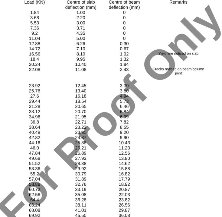
Table 4.1: shows the readings of MRS > MRB frame model and its corresponding deflection
Load (KN) Centre of slab deflection (mm)
Centre of beam deflection (mm)
Remarks
1.84 1.00 0
3.68 2.20 0
5.53 3.00 0
7.36 3.71 0
9.2 4.35 0
11.04 5.00 0
12.88 6.26 0.30
14.72 7.10 0.67
16.56 8.10 1.02 Yield line noticed on slab
18.4 9.95 1.32
20.24 10.40 1.84
22.08 11.08 2.43 Cracks noticed on beam/column
joint
23.92 12.45 3.30
25.76 13.40 3.80
27.6 16.18 4.94
29.44 18.54 5.73
31.28 20.65 6.46
33.12 20.70 6.84
34.96 21.95 6.99
36.8 22.71 7.82
38.64 23.22 8.55
40.48 23.90 9.20
42.32 24.87 9.90
44.16 25.88 10.43
46.0 26.21 11.23
47.84 26.89 12.56
49.68 27.93 13.80
51.52 28.88 14.62
53.36 29.92 15.88
55.2 30.79 16.82
57.04 31.89 17.79
58.88 32.76 18.92
60.72 33.19 20.87
62.56 35.08 22.03
64.4 36.28 23.82
66.24 38.11 26.56
68.08 41.01 29.87
69.92 45.50 36.08
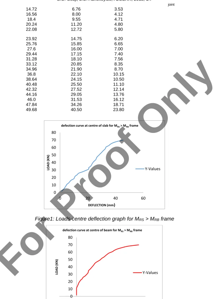
Table 4.2: shows the readings of MRS < MRB frame model and its corresponding deflection
Load (KN) Centre of slab deflection (mm)
Centre of beam deflection (mm)
Remarks
1.84 0.14 0.24
3.68 1.06 0.43
5.53 1.45 0.83
7.36 2.31 1.32
9.2 3.26 1.78 Yield line noticed on slab
11.04 4.31 2.33
12.88 5.47 3.01 Cracks noticed on beam/column
S.O. Osuji, L.O. Adhekoyibo, AJOERR, 2018, 1:7
joint
14.72 6.76 3.53
16.56 8.00 4.12
18.4 9.55 4.71
20.24 11.20 4.80
22.08 12.72 5.80
23.92 14.75 6.20
25.76 15.85 6.65
27.6 16.00 7.00
29.44 17.15 7.40
31.28 18.10 7.56
33.12 20.85 8.35
34.96 21.90 8.70
36.8 22.10 10.15
38.64 24.15 10.50
40.48 25.50 11.10
42.32 27.52 12.14
44.16 29.05 13.76
46.0 31.53 16.12
47.84 34.26 18.71
49.68 40.50 23.80
Figure1: Loads-centre deflection graph for MRS > MRB frame
Figure 2: Loads-edge deflection graph for MRS > MRB frame
0 10 20 30 40 50 60 70 80
0 20 40 60
LO
A
D
(K
N)
DEFLECTION (mm)
defection curve at centre of slab for MRS> MRBframe
Y-Values
0 10 20 30 40 50 60 70 80
-10 0 10 20 30 40
LO
A
D
(K
N)
DEFLECTION (mm)
defection curve at centre of beam for MRS> MRBframe
Y-Values
Figure 3: Loads-centre deflection graph for MRS < MRB frame
Figure 4: Loads-centre deflection graph for MRS < MRB frame
ANALYSIS AND DISCUSSIONS OF RESULTS
For the MRS > MRB frame model; it was observed that through the reading in dial gauges that deflection started on the centre of the slab. Deflection was noticed also on the beams at 12.88KN load. As the load increases, the deflections increases, deflections increase and the deflection of the slab was higher than that of the beam.
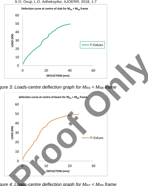
Under the load of 16.56KN, yield line patterns were noticed on the slab and at 22.08KN of load, cracks were noticed on the beam/columns joint across the span of the beams and laterally
under the slab. Load was applied continually until there was a sudden collapse of the model at a load of 69.92KN.See 5 and 6
Also for the MRS < MRB frame model, it was also observed that through the reading in dial gauges that deflection started on both the centre of the slab and beam respectively. The deflection increases and the deflection of the slab were also higher than that of the beam.
Under the load of 9.2KN, yield lines patterns were noticed on the slab and at 12.88KN of load, cracks were noticed on the beam/column joint across the span of the beams and laterally 0
10 20 30 40 50 60
0 20 40 60
LO
A
D
(K
N)
DEFLECTION (mm)
Defection curve at centre of slab for MRS< MRBframe
Y-Values
0 10 20 30 40 50 60
0 10 20 30
LO
A
D
(K
N)
DEFLECTION (mm)
defection curve at centre of beam for MRS< MRBframe
Y-Values
S.O. Osuji, L.O. Adhekoyibo, AJOERR, 2018, 1:7
under the slab. At an applied load of 49.68KN there was also a sudden collapse of the model.
In summary, the estimated collapsed load for the beam was 52.27KN/m, while that of slab was 20.36KN/m. the actual collapse load for MRS>MRB and MRS<MRB frame model was
69.92KN/m and 49.68KN/m respectively. Failure was due to Flexural failure at the beams /column joints. The actual collapse load of 69.92KN and 49.68KN respectively were greater than that of the estimated collapse loads of beam and slab. See 7 and 8
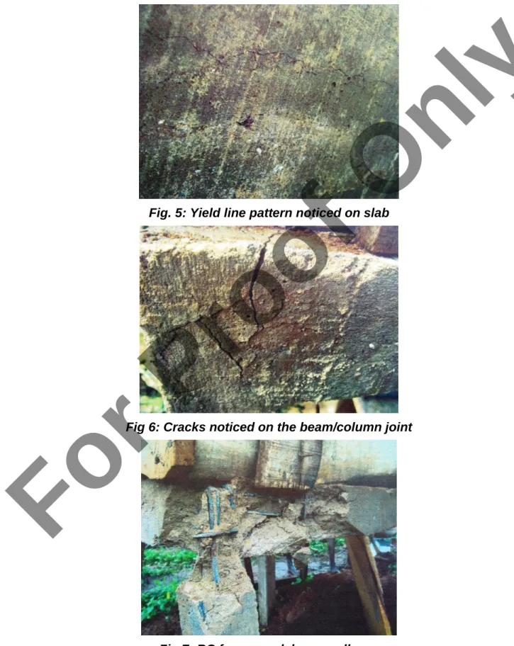
Fig. 5: Yield line pattern noticed on slab
Fig 6: Cracks noticed on the beam/column joint
Fig 7: RC frame model near collapse
Fig 8: Collapsed RC frame model.
CONCLUSION AND RECOMMENDATION
Conclusion
In conclusion, it can be deduced that the collapse load of the space frame model when MRS > MRB is greater than when MRS < MRB. Also, the slab of the MRS > MRB frame model is stronger than that of the MRS < MRB frame model, that is, the MRS > MRB frame Model can withstand more imposed load than the MRS < MRB frame model.
Therefore, it was observed that the collapse took place at the joint between the beam and column, and centre of the beam due to flexural failure after the formation of plastic hinges at the beam/column joints and beam centre.
Recommendation
The actual collapse load of the frame models are greater than the estimated ones, hence the design formulae must be looked into so as to reflect the behavior of reinforced concrete (R.C) structures under loading.
REFERENCES
1. Olanitori, L.M., Afolayan, J.O. and Arum, C. (2014), mode of collapse of square single panel reinforced concrete space framed structures with beam/column joints hinged. Research journal in Engineering and Applied Sciences 3(5) 358-365 2. Olaleye, T.O., Olanitori, L.M. and O.A. Aikulola
(2013), Theoretical and Practical Collapse Load of a Single Panel Space Frame: A Comparative Analysis Approach. Research journal in
Engineering and Applied Sciences 5(12) 3249-3261
3. Babatope, A. (2009), determination of collapse load of a square space framed RC model under loading.
4. Couchman, G.H. (1997), Design of semi-Continuous Braced Frames. SCI Publication pp-183. The Steel Construction institute. Ascot. 5. Mosley, W.H. and Bungey, J.N. (1993),
Reinforced Concrete Design. The Macmillan press Ltd., London pp 24
6. Astill, A.W. and Martin, L.H. (1982), Elementary structural design in concrete to CP 110. Edward Arnold (publishers) Ltd. London. Pp.16
7. Olanitori, L.M. and Olatuah, A.O. (2005). The effect of clayey impurities in sand on the crushing strength of concrete (A case study of sand in Akure metropolis, Ondo State, Nigerial) 30th
conference on our world in concrete and structure. 23-24 Aug. 2005 Singapore pp 373-376.
8. Akintola, O.A, Fakorede, A.S. and Osutade, A.O. (2009), comparative analysis of theoretical and experimental collapse load of square single panel space frame.
9. Horne, M.R. (1964), Safe loads on I-section columns in structures designed by plastic theory. Proceeding of the institution of Civil Engineers, 29. September, pp. 137-150.
10. Nethercot, D.A. (19860, the behavior of steel frame structures allowing for semi-rigid joint action. Steel structures-recent research advances and their application to design. (ed. Pavlovic), Elsevier Applied Science Publishers, London. pp. 135-151.
11. Nethercot, D.A. and Chen, W.F. (1988), Effect of connections of columns. Journal of constructional Steel Research. 10. Pp. 201-239.
S.O. Osuji, L.O. Adhekoyibo, AJOERR, 2018, 1:7
12. Darkov, A.V. and Schaposhnikov, N.N. (1986), Structural Mechanics. High School Publishers, Moscow.
13. Baikov, V.N. (1986), Structural Construction. High School Publishers, Moscow. Pp. 455-456 14. Moy, S.S.J, 1981. Plastic Methods for Steel and
Concrete Structures, 1st Edition, The Macmillan
Press Ltd
15. Pampanin, S., Magenes, G. and Carr, A.(2003), Modelling of Shear Hinge Mechanism in poorly
Detailed RC Beam-Column Joints, Proceeding of the fib Symposium Concrete Structures in Seismic Regions, Athens, paper n. 171,2003 16. Pampanin, S., Magenes, G., Calvi, G.M.(2003b),
Seismic Response of Reinforced Concrete Buildings Designed for Gravity Loads. Part II: Experimental Test on a Three Storey Frame, submitted to ASCE Journal of Structural Engineering.