Sharif University of Technology
Scientia IranicaTransactions B: Mechanical Engineering http://scientiairanica.sharif.edu
Numerical and experimental study of the eect of the
process parameters on the void evolution in the cold
extrusion of rods
M. Rajabzadeh Gatabi, H. Afrasiab
, and A. Moazemi Goudarzi
Department of Mechanical Engineering , Babol Noshirvani University of Technology, Babol, Iran. Received 31 December 2017; received in revised form 11 July 2018; accepted 31 December 2018KEYWORDS Void evolution; Cold extrusion; Finite element model; Die geometry; Void location.
Abstract. The elimination of defects such as voids and internal cavities is required in metal-forming processes to avoid premature failure of mechanical components during service. In this paper, the eect of dierent parameters on the void closure behavior is studied in the cold extrusion of rods. A three-dimensional nonlinear dynamic nite element model is developed for this purpose. Experiments are also performed on aluminum samples to verify the accuracy of the nite element model. Results of the developed model are in good agreement with experimental ndings. It is observed that voids contract in all directions during the direct extrusion, which is in contrast to some other metal-forming processes such as forging and rolling. The eects of parameters such as die semi-angle, friction coecient, and void location on the void evolution are systematically investigated and discussed. The results of this study can help industries using metal extrusion for optimized design and control of the process to reduce voids and porosity and increase the strength of their product.
© 2020 Sharif University of Technology. All rights reserved.
1. Introduction
Internal defects such as voids and porosity usually occur due to shrinkage and gas progression during the solidication of the casting ingots [1,2]. The presence of these defects in the nal product adversely aects its mechanical properties and may disturb its performance and shorten its life [3]. Consequently, the reduction of these defects is of prime importance for industrial applications [4{6].
Void elimination is usually performed by applying large compressive plastic deformation in the material by means of dierent metal-forming processes [7{9]. *. Corresponding author. Tel.: +98 11 35501345;
Fax: +98 11 32334201
E-mail address: [email protected] (H. Afrasiab). doi: 10.24200/sci.2018.50154.1540
Direct extrusion, in which the billets are subjected to high compressive and shear stresses, is capable of reducing the defects in the metal structure [10] and can be eectively used for void elimination during the manufacturing of mechanical parts.
The void closure behavior during metal-forming processes has been the subject of many studies in recent years. Kakimoto et al. [9] examined the closing behavior of internal voids in dierent congurations of the cold forging process by a deformation analysis involving the nite element method. To conrm the accuracy of the deformation analysis, experiments were carried out on pure aluminum billets through which the cylindrical hole was drilled. Chen et al. [8] developed a procedure based on nite element analysis and neural network to predict the degree of void closure in cold rolling. Experiments were conducted on aluminum sheets to validate the developed model. Two types of voids, namely a cylinder void (a longitudinal hole
through the width of the sheet) and a spherical void, were considered in their study. Kim et al. [11] carried out numerical analysis to explore various parameters such as the ratio of height to diameter of ingot, pressing depth, and void location and their eects on the void evolution in the forging process. Pure lead specimens containing spherical voids were employed to perform verication tests. Chen et al. [12] proposed a mathematical methodology based on strain function for analyzing void closure in the forging process of steel ingots. They obtained a mathematical criterion for on-center and o-center void closure and veried the criterion by nite element simulations. Chen et al. [13] employed a nonlinear coupled nite element model to investigate the deformation mechanism of internal spherical void defects during the hot radial forging process. They investigated the eect of void location, die shape, and reduction of the tube thickness on the void closure behavior. Chen and Lin [14] examined the evolution mechanisms for the spherical or spheroidal voids during hot working by nite element simulations and experiments. They discussed the eect of the initial void size, aspect ratio, and position on the void evolution, and argued that the strain and stress elds around voids were the key factors inuencing the void closure. Park [15] investigated the closure phenomenon of cylindrical voids in at-die forging by rigid-plastic nite element analysis and experiments using plasticine specimens. Saby et al. [16] used a representative volume element to simulate spherical and ellipsoidal voids on the meso-scale. They performed a sensitivity study of mechanical parameters, and concluded that the strain rate had no major inuence on the closure of a real void. Saby et al. [6] presented a geometry-dependent model for void closure in the hot metal-forming process that was capable of accounting for the void's geometry and orientation, as well as the mechanical state during deformation.
The review of the existing literature reveals that most of the reported studies on the void closure phenomenon in metal-forming problems focused on forging or rolling [7]. This is common since forging and rolling are the most ecient methods for the elimination of internal voids and porosity. Neverthe-less, the investigation of the void evolution in other metal-forming processes, such as extrusion, can provide useful information and help industry to optimize the design and control of forming processes. Accordingly, in the present study, the eect of process parameters on the void closure behavior is investigated in the cold extrusion process. A three-dimensional nonlinear dynamic nite element model is used for this purpose. Experiments are performed to validate the accuracy of the developed nite element model. The void reduction predictions by the developed model are in good agreement with experimental results.
2. Description of the analysis procedure 2.1. Void geometry
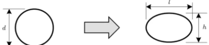
The void cross-section is assumed to have initially a circular shape that turns into an elliptical shape after extrusion. Figure 1 shows the void dimensions before and after deformation; d is the void initial diameter, while h and l are its nal height and length.
In order to characterize the void evolution during extrusion, three parameters, i.e., void height reduction (rh), void length reduction (rl), and void area reduction
(rA), are dened as follows [13]:
rh= h dd ; rl= l dd ; rA=AfA Ai
i ; (1)
where Ai and Af are the void initial and nal
cross-sectional areas, respectively. From these relations, it can be seen that the void is completely closed when rA
reaches its limiting value (i.e., rh = 1 and/or rl =
1). Furthermore, a lower value is favorable for these parameters as it corresponds to a smaller void after extrusion.
2.2. Finite element modeling
A schematic of the direct extrusion of rods is shown in Figure 2. The die semi-angle is depicted by in this gure.
A three-dimensional nonlinear dynamic nite el-ement model has been developed by Abaqus/explicit nite element software to examine the void evolution behavior in the cold direct extrusion. The formulation for the dynamic nite element analysis can be written as follows:
[Me] fueg + [Ke] fueg = fFeg ; (2)
where: [Me] =Z
V[N]
T[N]dV; [Ke] =Z V[B]
T[C][B]dV: (3)
In these equations, fueg and fFeg are the displacement
Figure 1. Void geometry before and after extrusion.
and force vectors, respectively; [Me] is the mass matrix;
[Ke] is the stiness matrix; denotes the material
den-sity; [C] represents the elastic-plastic stiness tensor; [N] is the element shape function matrix; and [B] refers to the element strain-displacement matrix.
The explicit central dierence integration rule is used to integrate Eq. (2). This gives:
fueg
(i)= [Me] 1
fFeg
(i) [Ke] fueg(i)
; f _ueg
(i+1=2)= f _ueg(i 1=2)+t(i+1)2+ t(i); fueg(i);
fueg
(i+1)= fueg(i)+ t(i+1)f _ueg(i+1=2): (4)
Subscript i in the above equations denotes the incre-ment number in an explicit dynamic step.
The workpiece material is aluminum 5010 alloy that is annealed at 350 for 1 hour and, then, cools
down to room temperature to decrease its ow stress and increase its formability. A standard compression test is performed on a sample made of the resultant material at room temperature, and the following power law is obtained for the relationship between the stress and the amount of plastic strain:
= 520"0:22
p : (5)
Similar power law equations have been previously used in many related studies, e.g., in [17{19]. The associated strain-stress curve is shown in Figure 3. It should be noted that since the process is implemented at room temperature and the ram velocity is low (0.1 mm/s), it is fair to assume the process as quasi-static and neglect the strain rate eect [20,21]. An elastic-plastic material model created from the von Mises yield surface and associated ow rule is used to describe workpiece deformation. The temperature rise is also ignored because the heat generated by the mechanical work is transferred to the surroundings and
Figure 3. The strain-stress curve for the sample material (aluminum 5010).
Figure 4. Dierent positions of voids in the workpiece.
the material does not experience any changes in its microstructure [22,23]. In fact, in the cold extrusion, the temperature rise is important only if the extrusion ratio or ram speed is very high or when the process is adiabatic, which is not the case here [24]. Eight-node brick elements with reduced integration and hourglass control are used to mesh the workpiece model.
Die and punch are modeled as rigid bodies in the FEM simulations since their deformation is negligible. Four-node three-dimensional bilinear rigid quadrilat-eral elements are used to create their FEM mesh. A constant friction coecient is assumed between workpiece and die in the range of = 0:05 to = 0:02, which is a common assumption in cold metal-forming processes [17,18]. The Coulomb friction law is used to dene the friction in the contact areas. The voids are assumed to be cylindrical with a circular cross-section and to be positioned at on-center or o-center of the workpiece cross-section, as shown in Figure 4. In order to reduce the computational cost, a quarter model is used for the workpiece with on-center void and a half model for the workpiece with o-center void. The dimensions of workpiece and die and the size of voids are based on the parameters of the experimental tests, which are given in the following sections.
2.3. Model verication
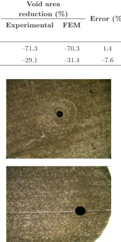
The described nite element model was veried based on the results of experiments performed on two cylin-drical samples of 30 mm in diameter and 60 mm in length. A void with a radius of about 2.2 mm was drilled through the length of each sample. The void was on-center in one of the samples and o-center in the other one, as shown in Figure 5. The diameter of these voids was accurately measured by a microscope with a micrometer scale eyepiece. A microscopic view of the voids' cross-section is provided in Figure 6.
The samples were then extruded in a die with a semi-angle of = 30. Subsequently, the extruded
products were wire-cut by an electric discharge machine near their tips. Figure 7 shows the products after the
Table 1. Comparison of nite element and experimental results. Void
position
Void initial diameter (mm)
Void nal dimensions (mm)
Void area
reduction (%) Error (%)
Experimental FEM Experimental FEM
d l h l h
On-center 4.48 2.40 2.40 2.44 2.44 {71.3 {70.3 1.4
O-center 4.32 3.80 3.48 3.66 3.50 {29.1 {31.4 {7.6
Figure 5. Samples used in the experimental tests.
Figure 6. A microscopic view of the voids before extrusion.
Figure 7. Extruded products and their wire-cut surface (from left to right: void-less, with on-center, and o-center voids).
Figure 8. A view of voids under microscope after extrusion.
wire-cut process. A microscopic view of the voids in the wire-cut surface is provided in Figure 8.
The void dimensions were measured on the wire-cut surface under microscope. Table 1 presents the experimental and nite element results for the voids' dimensions after extrusion. The results show that the dierence between experimental and FEM data for the void area reduction is about 1.4% for the on-center void and 7.6% for the o-center void. This indicates good agreement between experimental and simulation results. The friction coecient was assumed to be = 0:15 for both on-center and o-center cases. This value gave the best agreement between experimental and nite element predicted ram forces.
3. Results and discussion
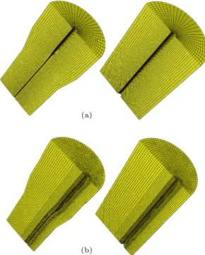
Figure 9 shows the nite element model of workpieces with on-center and o-center voids before and after simulation. It should be noted that the quarter model of the workpiece with the on-center void is mirrored to a half model in Figure 9(a) to have a better view of the workpiece and void geometry and deformation. The mesh independence study of both cases was conducted to ensure that the mesh size was not inuencing results.
Figure 9. Finite element model of the workpiece with (a) on-center void and (b) o-center void.
Figure 10. Variation of void area reduction, rA, for (a) on-center void and (b) o-center void.
3.1. Eect of the die semi-angle and friction coecient
Figure 10 shows the variation of the void area reduc-tion, rA, with die semi-angle and friction coecient
for on-center and o-center voids. As shown in this gure, regardless of the void position in the workpiece, the void reduction increases with the reduction of die angle and friction coecient.
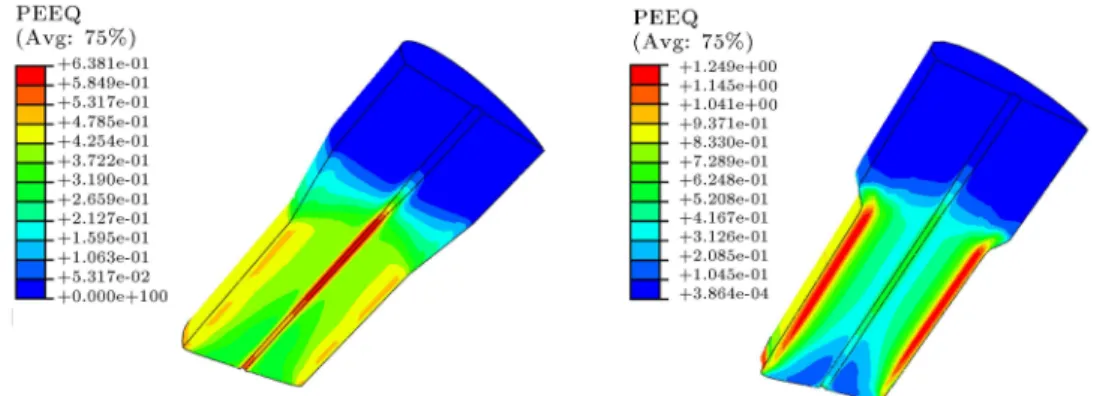
The plastic eective strain distribution in work-pieces extruded by dies with = 10 and =
40 is presented in Figure 11. It can be seen that
the workpiece experiences larger plastic strain when extruded by a die with a greater semi-angle. However, the maximum plastic deformation occurs in regions near the workpiece surface in this case. However, extrusion in dies with a small semi-angle creates a more uniform deformation in the workpiece, and the maximum plastic strain occurs inside the workpiece where internal voids and other defects are located. Consequently, dies with a smaller semi-angle lead to a greater void area reduction and are recommended for better void closure.
A pattern of material deformation in the work-piece cross-section obtained by a coarse mesh is plotted in Figure 12 for low and high friction conditions in blue and red colors, respectively. This pattern clearly shows that, in the low friction condition, the deformation is uniform throughout the workpiece and can contribute to the closure of voids located every-where in the workpiece. However, in higher friction conditions, the plastic deformation is less uniform and more concentrated near the contact area between the die and workpiece. Consequently, it has a less profound eect on the internal voids closure, as predicted in Figure 10.
3.2. Eect of the void position
Figure 13 shows variations of the on-center and o-center void area reduction with the die semi-angle for friction coecients of = 0:05 and = 0:2. It is seen in this gure that rA for the on-center void is
more sensitive to the die semi-angle. In other words, variations of the die semi-angle have a greater eect on the closure of voids located on or near the center of the workpiece.
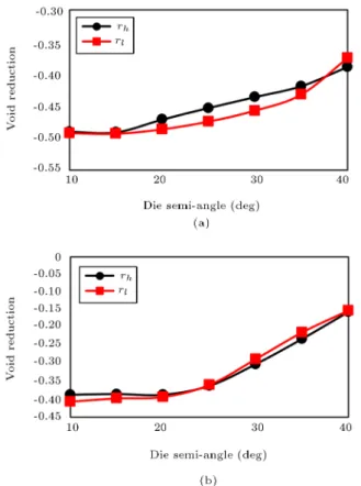
Figure 14 shows rh and rl variations by the die
semi-angle for the workpiece with the o-center void in friction coecients of = 0:05 and = 0:2, respectively. According to these gures, when friction is small, the absolute value of rl is greater than that
of rh. This means that the void contraction in the
hoop direction is greater than its contraction in the radial direction. This, however, changes as the friction coecient increases. At higher frictions, the absolute value of rlis getting smaller than that of rh, especially
in the dies with larger semi-angles. In other words, the void contraction in the radial direction exceeds its contraction in the hoop direction as friction increases between die and workpiece. It is worth noting that both rh and rl are negative in all conditions for both
Figure 11. Plastic eective strain distribution in workpieces extruded by dies with = 10(left) and = 40(right).
Figure 12. Pattern of workpiece deformation on a coarse mesh in low (blue) and high (red) friction conditions.
on-center and o-center voids. This indicates that the voids contract in all directions during direct extrusion. This is in contrast to many other metal-forming pro-cesses like rolling and forging in which void contraction in one direction is accompanied by expansion in the perpendicular direction, as demonstrated in previous studies [6,8].
4. Conclusions
A three-dimensional nonlinear dynamic nite element model was developed in this paper to study the eect of dierent parameters on the void evolution in the cold extrusion of rods. The accuracy of the model was conrmed by experiments performed on the alu-minum samples containing longitudinal on-center and o-center voids with a circular cross-section. It was
Figure 13. Variation of rA for on- and o-center voids in (a) = 0:05 and (b) = 0:2.
observed that, in contrast to some other metal-forming processes such as forging and rolling, the voids contract in all directions during direct extrusion. Furthermore, regardless of the void position, the void reduction increased with the reduction of the die semi-angle and friction coecient. However, voids that are closer to the workpiece center are more sensitive to the die semi-angle. Moreover, it was found that when friction was small, the contraction of o-center voids in the hoop direction was greater than that in the radial direction. However, in the high friction condition, the void contraction in the radial direction exceeds its
Figure 14. Variation of rhand rlfor o-center void in (a) = 0:05 and (b) = 0:2.
contraction in the hoop direction, especially in dies with larger semi-angles.
Acknowledgements
The authors acknowledge the funding support of Babol-Noshirvani University of Technology through Grant Program No. BNUT/389003/97.
References
1. Chen, M.-S., Lin, Y.C., and Chen, K.-H. \Evolution of elliptic-cylindrical and circular-cylindrical voids inside power-law viscous solids", Int. J. Plast., 53(1), pp. 206{227 (2014).
2. Vladimirov, I.N., Pietryga, M.P., Kiliclar, Y., Tini, V., and Reese, S. \Failure modelling in metal forming by means of an anisotropic hyperelastic-plasticity model with damage", Int. J. Damage Mech., 23(8), pp. 1096{ 1132 (2014).
3. Saby, M., Bernacki, M., and Bouchard, P.-O. \Under-standing and modeling of void closure mechanisms in hot metal forming processes: A multiscale approach", Procedia Eng., 81(1), pp. 137{142 (2014).
4. Kittner, K., Wiesner, J., and Kawalla, R. \A new approach for void closure in bulk metal forming", Key Eng. Mater., 716(3), pp. 595{604 (2016).
5. Patel, M., Kim, H.-S., Park, H.-H., and Kim, J. \Active adoption of void formation in metal-oxide for
all transparent super-performing photodetectors", Sci. Rep., 6(2), p. 25461 (2016).
6. Saby, M., Bouchard, P.-O., and Bernacki, M. \A geometry-dependent model for void closure in hot metal forming", Finite Elem. Anal. Des., 105(4), pp. 63{78 (2015).
7. Saby, M., Bouchard, P.-O., and Bernacki, M. \Void closure criteria for hot metal forming: A review", J. Manuf. Process., 19(1), pp. 239{250 (2015).
8. Chen, J., Chandrashekhara, K., Mahimkar, C., Lekakh, S.N., and Richards, V.L. \Void closure pre-diction in cold rolling using nite element analysis and neural network", J. Mater. Process. Technol., 211(2), pp. 245{255 (2011).
9. Kakimoto, H., Arikawa, T., Takahashi, Y., Tanaka, T., and Imaida, Y. \Development of forging process design to close internal voids", J. Mater. Process. Technol., 210(3), pp. 415{422 (2010).
10. Huang, G., Han, Y., Guo, X., Qiu, D., Wang, L., Lu, W., and Zhang, D. \Eects of extrusion ratio on microstructural evolution and mechanical behavior of in situ synthesized Ti-6Al-4V composites", Mater. Sci. Eng. A., 688(1), pp. 155{163 (2017).
11. Kim, Y., Cho, J., and Bae, W. \Ecient forging process to improve the closing eect of the inner void on an ultra-large ingot", J. Mater. Process. Technol., 211(6), pp. 1005{1013 (2011).
12. Chen, K., Yang, Y., Shao, G., and Liu, K. \Strain function analysis method for void closure in the forging process of the large-sized steel ingot", Comput. Mater. Sci., 51(1), pp. 72{77 (2012).
13. Chen, J., Chandrashekhara, K., Mahimkar, C., Lekakh, S.N., and Richards, V.L. \Study of void closure in hot radial forging process using 3D nonlinear nite element analysis", Int. J. Adv. Manuf. Technol., 62(9), pp. 1001{1011 (2012).
14. Chen, M.-S. and Lin, Y.C. \Numerical simulation and experimental verication of void evolution inside large forgings during hot working", Int. J. Plast., 49(2), pp. 53{70 (2013).
15. Park, J.-J. \Finite-element analysis of cylindrical-void closure by at-die forging", ISIJ Int., 53(8), pp. 1420{ 1426 (2013).
16. Saby, M., Bernacki, M., Roux, E., and Bouchard, P.-O. \Three-dimensional analysis of real void closure at the meso-scale during hot metal forming processes", Comput. Mater. Sci., 77(3), pp. 194{201 (2013).
17. Saboori, M., Bakhshi-Jooybari, M., Noorani-Azad, M., and Gorji, A. \Experimental and numerical study of energy consumption in forward and backward rod extrusion", J. Mater. Process. Technol., 177(1), pp. 612{616 (2006).
18. Noorani-Azad, M., Bakhshi-Jooybari, M., Hos-seinipour, S.J., and Gorji, A. \Experimental and nu-merical study of optimal die prole in cold forward rod extrusion of aluminum", J. Mater. Process. Technol., 164(2), pp. 1572{1577 (2005).
19. Bakhshi-Jooybari, M., Saboori, M., Noorani-Azad, M., and Hosseinipour, S.J. \Combined upper bound and slab method, nite element and experimental study of optimal die prole in extrusion", Mater. Des., 28(6), pp. 1812{1818 (2007).
20. Koc, M., Hydroforming for Advanced Manufacturing, Elsevier (2008).
21. Palumbo, G., Sorgente, D., and Tricarico, L. \A numerical and experimental investigation of AZ31 formability at elevated temperatures using a constant strain rate test", Mater. Des., 31(3), pp. 1308{1316 (2010).
22. Chen, D.-C., Chang, D.-Y., Chen, F.-H., and Kuo, T.-Y. \Application of ductile fracture criterion for tensile test of zirconium alloy 702", Sci. Iran., 25(2), pp. 824{ 829 (2018).
23. A Nurul, M. and Syahrullail, S. \A new approach for cold extrusion process: Dimples indentation on sliding contact surface and palm oil as an alternative lubricant", Sci. Iran., 24(6), pp. 2875{2886 (2017).
24. Saha, P.K. \Aluminum extrusion technology", ASM International: Materials Park, 1(3), pp. 112{115 (2000).
Biographies
Moein Rajabzadeh Gatabi received his MS degree in Mechanical Engineering from Noshirvani University of Technology, Babol, Iran, 2016. He is currently a Teacher at the Department of Mechanical Engineering, Hasanzadeh Amoli University, Amol, Iran. His main research interests are nite element simulation and modeling of metal-forming processes.
Hamed Afrasiab received his BS, MS, and PhD degrees all in Mechanical Engineering from Sharif University of Technology, Tehran, Iran in 2004, 2006, and 2011, respectively. He is currently a Professor at the Department of Mechanical Engineering, Babol University of Technology, Babol, Iran. His main research interests are nite element simulation of the solid, uid and uid-structure interaction problems, stress-strain analysis, and modeling of metal-forming processes.
Ali Moazemi Goudarzi obtained his BSc degree in Manufacturing Eng. from University of Tabriz (1990), Tabriz, Iran, MS degree In Robotics from UPMC (1995), Paris, France, and PhD degree in Manufacturing Eng. From University of Evry(2001), Evry, France. Currently, he is positioned as an Assistant Professor at the Department of Mechanical Engineering, Babol University of Technology, Babol, Iran. His main research interests are biomechanics and stress-strain analysis.