Sharif University of Technology
Scientia IranicaTransactions F: Nanotechnology www.scientiairanica.com
Eect of position of a square-shaped heat source on
buoyancy-driven heat transfer in a square cavity lled
with nanouid
A. Arefmanesh
a, M. Mahmoodi
a,b;and M. Nikfar
ca. Department of Mechanical Engineering, University of Kashan, Ghotb-e-Ravandi Boulevard, Kashan, Iran. b. Department of Mechanical Engineering, Amirkabir University of Technology, 424 Hafez Ave, Tehran, Iran.
c. Department of Mechanical Engineering, K.N. Toosi University of Technology, 470 Mirdamad Ave. West, 19697, Tehran, Iran. Received 18 December 2012; received in revised form 22 June 2013; accepted 30 December 2013
KEYWORDS Natural convection; Nanouid;
Heat source; Square cavity; Finite volume method.
Abstract. Buoyancy-driven heat transfer, due to a square-shaped heater placed inside a square cavity lled with TiO2-water nanouid, is investigated numerically. The heater
is maintained at a constant temperature, Th, while the cavity walls are kept at a lower
constant temperature, Tc. The governing equations are solved using the nite volume
method and the SIMPLER algorithm. The simulations are performed for six dierent positions of the heat source inside the cavity, a range of Rayleigh numbers from 103to 106,
and dierent volume fractions of the nanoparticles. The ratio of the height (width) of the heat source to that of the cavity is taken as 0.2. The results shows that the uid ow and heat transfer characteristics inside the cavity strongly depend on the location of the heat source. For Ra = 103, i.e. a conduction-dominated heat transfer regime, maximum heat
transfer rate is achieved by placing the heat source close to the corners of the cavity, while, for Ra = 106, positioning the heat source near the middle of the cavity's bottom wall yields
the maximum average Nusselt number. Moreover, it is observed that the average Nusselt number is generally an increasing function of the volume fraction of the nanoparticles.
c
2014 Sharif University of Technology. All rights reserved.
1. Introduction
Natural convection uid ow and heat transfer inside enclosures are encountered in a number of industrial applications, such as solar collectors, heat exchangers, home ventilation, and electronic cooling devices. The low thermal conductivity of conventional uids such as water and oil is a preeminent disadvantage in heat exchanging apparatus. Recently, nanouids, which have relatively higher thermal conductivity compared to that of pure uids, have been considered to enhance the rate of heat transfer in such devices.
*. Corresponding author. Tel.: +98 9126514920 E-mail addresses: [email protected] (A. Arefmanesh); [email protected] (M. Mahmoodi); [email protected] (M. Nikfar)
Khanafer et al. [1] are among the rst investiga-tors to have studied natural convection heat transfer in nanouid-lled enclosures numerically. They observed that for the considered range of Grashof number, the Nusselt number increased with an increase in the volume fraction of the nanoparticles. Abu-Nada et al. [2] employed the nite volume method to investigate the buoyancy-driven heat transfer in a space between two dierentially-heated concentric cylinders lled with nanouids. Based on their observations, for high Rayleigh numbers, the heat transfer was signicantly enhanced for nanoparticles with high thermal con-ductivity, while, for intermediate values of Rayleigh number, using nanoparticles with low thermal conduc-tivity resulted in reductions in heat transfer rate. In another numerical study, Santra et al. [3] considered the buoyancy-driven uid ow and heat transfer of
Cu-water nanouid in a dierentially-heated square cavity. They observed that the heat transfer rate decreased with increasing the volume fraction of the nanoparticles for Rayleigh numbers between 104 and 107. Oztop
and Abu-nada [4] used the nite volume method to study the natural convection heat transfer in a Cu-water nanouid-lled rectangular cavity with a cold vertical wall, an imbedded heater counterpart wall, and insulated horizontal walls. Their results showed that the average Nusselt number increased with increasing the volume fraction of the nanoparticles for Rayleigh numbers between 103 and 105. In another numerical
work, Abu-nada and Oztop [5] used the nite volume method to study natural convection heat transfer in an inclined square cavity lled with Cu-water nanouid. Their results indicated that addition of nanoparticles to the base uid resulted in signicant heat transfer enhancement. Aminossadati and Ghasemi [6] inves-tigated the free convection of dierent water-based nanouids in a square cavity having a constant ux heater on its horizontal bottom wall, numerically. The remaining cavity walls were kept at a relatively lower temperature. They observed that adding nanoparticles to water improved the heat transfer performance. Ghasemi and Aminossadati [7] studied periodic nat-ural convection of nanouid in a square cavity with insulated top and bottom walls, a cold right vertical wall, and an oscillating ux heat source on its left vertical wall. They observed that adding nanoparticles to the base uid enhanced heat transfer, especially at low Rayleigh numbers. Oztop et al. [8] conducted a numerical study on free convection in a nanouid-lled inclined square enclosure, subjected to heating and cooling by sinusoidal temperature proles on one of its sides. They reported enhancements of heat transfer rate for the entire range of considered Rayleigh numbers. In another study, Sheikhzadeh et al. [9] inves-tigated the natural convection of TiO2-water nanouid
in rectangular cavities, with dierentially-heated left and top walls and insulated remaining walls. Their results showed that by increasing the volume fraction of the nanoparticles, the average Nusselt number of the hot wall increased for shallow cavities, while a contrary trend was observed for tall ones. Analytical and numerical results on the free convection of a nanouid in a shallow cavity heated from below and cooled from the ceiling were reported by Alloui et al. [10]. They observed that the enhancement of heat transfer due to the presence of nanoparticles depended on the value of the Rayleigh number. A numerical study on natural convection of CuO-water nanouid in a cavity with two pairs of heat source-sink on its bottom wall was conducted by Aminossadati and Ghasemi [11]. Their results showed that regardless of the position of the pairs of source-sink, the heat transfer rate increased with increasing the Rayleigh
number and the volume fraction of the nanoparticles. In another numerical study, Nasrin and Parvin [12] used the nite volume method to investigate the free convection heat transfer in a trapezoidal cavity with dierentially heated side walls lled with Cu-water nanouid. They observed that Cu nanoparticles with the lowest aspect ratio are established to be most eective in enhancing the performance of heat transfer rate. Nikfar and Mahmoodi [13] investigated the free convection heat transfer of a nanouid in a square cavity with wavy side walls using the meshless local Petrov-Galerkin method.
As far as very recent studies on the natural convection inside nanouid-lled enclosures with a hot block or rib on the wall are concerned, Mahmoudi et al. [14] conducted a numerical study on the natural con-vection cooling of a heat source horizontally attached to the left vertical wall of a cavity lled with copper-water nanouid. They observed that the average Nusselt number increased with Rayleigh number and volume fraction of the nanoparticles, while it decreased with an increase in length of the heater. In another work, Mahmoudi et al. [15] studied the natural convection of copper-water nanouid in an open cavity with two vertically mounted heaters on the horizontal walls. Their results indicated that the ow and temperature elds were strongly dependent on the Rayleigh number and the position of the heat sources. Eects of nanoparticles on enhancement of heat transfer in a U-shaped cavity were studied by Cho et al. [16]. Mah-moodi [17] and MahMah-moodi and Hashemi [18], in two consecutive papers, conducted nite volume numerical studies of the natural convection heat transfer in L- and C-shaped cavities containing nanouids, respectively. They concluded that the eect of nanoparticles on the heat transfer enhancement for narrow enclosures was more than that for wide enclosures. Dehnavi and Rezvani [19] considered a -shaped cavity and studied natural convection of Al2O3-water nanouid inside it.
There are some papers on the natural convection of nanouids in enclosures with inside heaters of dif-ferent shape. In a numerical study, Mahmoodi [20] investigated the eect of nanouid on heat transfer in a square cavity with a vertical or horizontal inside thin heater. Entropy generation, due to natural convection around a horizontal heat source in a square cavity containing nanouid, was studied by Shahi et al. [21]. Some observations about natural convection of nanouids in a square cavity with dierentially heated side walls and insulated horizontal walls can be found in the works of Sheikhzadeh et al. [22], Mahmoodi and Sebdani [23] and Aminossadati and Ghasemi [24]. Arefmanesh et al. [25] studied the buoyancy-driven heat transfer in two-square duct annuli lled with TiO2-water nanouid. They conducted a parametric
aspect ratio, and the volume fraction of nanoparticles on uid ow and heat transfer. Their results showed heat transfer enhancement in the presence of the nanoparticles. The results obtained by Matin and Pop [26] about natural convection of nanouids in eccentric annuluses stated that the position of the inner cylinder had a major eect on the rate of heat transfer. The above detailed literature survey reveals that, although many studies have been conducted on natural convection uid ow and heat transfer in nanouid-lled enclosures with dierent boundary conditions, no study exists on the eect of the position of a square-shaped heat source in a nanouid-lled cavity on the buoyancy-driven heat transfer inside the cavity. According to the ndings of Matin and Pop [26], the position of a heater in a cavity is an important parameter in the natural convection heat transfer process. The present study, therefore, concentrates only on this.
2. Problem formulation
A schematic diagram of the system composed of a square-shaped heat source inside the square cavity and the coordinates are depicted in Figure 1. Each side of the heat source and, also, each side of the cavity are denoted by h and H, respectively. The lengths of the heat square and the cavity perpendicular to the plane of the gure are long enough for the problem to be considered two-dimensional. The heat source and the cavity are maintained at dierentially-dierent constant temperatures of Thand Tc, respectively, with
Th > Tc. A special coordinate system (s) along the
walls of the cavity is adopted with its origin at x = 0 and y = 0, as identied by the dashed line in Figure 1. A dimensionless form of the special coordinate system is dened as S = s=H. The cavity is lled with
Figure 1. Natural convection due to a square-shaped heat source inside a cold square cavity.
Table 1. Thermophysical properties of the base uid and nanoparticles [4].
Physical properties
Base uid (water)
Nanoparticles (TiO2)
Cp(J/kg-K) 4179 686.2
(kg/m3) 997.1 4250
k (W/m-K) 0.613 8.9538
105 (K 1) 21 0.9
(kg/m-s) 0.001003 |
a nanouid composed of water and TiO2 spherical
nanoparticles. The nanouid is assumed to be incom-pressible, and the nanoparticles are presumed to be in thermal equilibrium with the base uid. Moreover, there is no slip between the nanoparticles and the water. The thermophysical properties of the base uid and the nanoparticles are presented in Table 1. The nanouid properties are considered to be constant, with the exception of its density in the buoyancy term of the momentum equation, which varies according to the Boussinesq approximation [27].
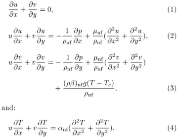
The equations for conservation of mass, mo-mentum, and energy for the two-dimensional steady laminar ow of the nanouid, incorporating natural convection via the Boussinesq approximation, are given by:
@u @x+
@v
@y = 0; (1)
u@u@x + v@u@y = 1
nf
@p @x +
nf
nf(
@2u
@x2 +
@2u
@y2); (2)
u@v @x + v
@v @y =
1 nf
@p @y +
nf
nf(
@2v
@x2 +
@2v
@y2)
+()nfg(T Tc)
nf ; (3)
and:
u@T@x + v@T@y = nf(@ 2T
@x2 +
@2T
@y2): (4)
A dimensionless form of the governing equations can be obtained via introducing the following dimensionless variables:
X = Hx; Y = Hy; U = uH
f ;
V = vH
f ; P =
pH2
nf2f; and =
T Tc
Th Tc: (5)
Substituting the above non-dimensional variables into the continuity, momentum, and energy equations
re-sults in the following dimensionless form of the govern-ing equations:
@U @X +
@V
@Y = 0; (6)
U@X@U + V@Y@U = @X@P +nf
nff(
@2U
@X2 +
@2U
@Y2); (7)
U@X@V + V@V@Y = @P@Y +nf
nff(
@2V
@X2 +
@2V
@Y2)
+() nf
nff RaPr; (8)
and:
U@X@ + V@Y@ = nf
f(
@2
@X2 +
@2
@Y2); (9)
where Rayleigh number, Ra, and Prandtl number, Pr, are dened as follows:
Ra = gf(Th Tc)H3
fvf ; and Pr =
vf
f: (10)
The boundary conditions for Eqs. (6)-(9) are: U = V = 0; = 1 on the heat source; and:
U = V = 0; = 0 on the walls of the cavity: (11) 2.1. Thermophysical properties of the
nanouid
The eective viscosity, nf, of the nanouid can be
esti-mated by the following empirical correlation proposed by Corcione [28]:
nf
f =
1
1 34:87(ds=df) 0:3'1:03; (12)
where df is the equivalent diameter of base uid
molecules and given by: df = 0:1
6M Nf0
1=3
; (13)
in which M is the molecular weight of the base uid, N is the Avogadro number, and f0is the mass density of
the base uid calculated at temperature T0 = 293 K.
The viscosity of the base uid (water) varies with temperature, according to the following equation:
H2O=
1:2723 T5
rc 8:736 Trc4 + 33:708
T3
rc 246:6 Trc2 + 518:78
Trc+ 1153:9
10 6; (14)
where Trc = log(T 273). Also, the thermal
conduc-tivity, knf, of the nanouid can be obtained from the
empirical correlation proposed by Corcione [28]: knf
kf = 1 + 4:4'
0:66 T
Tfr
10k s
kf
0:03
Pr0:66Re0:4;
(15) where T is the nanouid temperature, Tfris the freezing
point of the base liquid, ksis the nanoparticle thermal
conductivity, Pr is the Prandtl number of the base liquid, and Re is the nanoparticle Reynolds number, dened as:
Re = 2f2kbT
fds ; (16)
where symbol kb is the Boltzmann constant (kb =
1:3807 10 23 J / K).
The density, nf, heat capacity, (cp)nf, and
thermal expansion coecient, ()nf, of the nanouid
are obtained from the following respective relations [4]: nf = (1 ')f+ 'p; (17)
(cp)nf = (1 ')(cp)f+ '(cp)p; (18)
and:
()nf = (1 ')()f+ '()p: (19)
The thermal diusivity of the nanouid, nf, is
evalu-ated from the following relation: nf= (cknf
p)nf: (20)
The Nusselt number based on the height (width) of the cavity is evaluated from the following relation:
Nu = hnfkH
f : (21)
The heat transfer coecient for the nanouid, hnf, is
obtained from the following equation: hnf =T q
h Tc; (22)
where the wall heat ux per unit area, q, can be written as:
q = knfThHTc@n@jwall: (23)
Substituting Eqs. (22) and (23) into Eq. (21) yields the following relation for the Nusselt number along the walls of the cavity:
Nu = (kknf
f)
@
3. Computational details
The solution of the governing equations leads to a complete understanding of the velocity and tempera-ture elds for natural convection due to the square-shaped heat source inside the cavity. Consequently, the eects of the position and the temperature of the heat square on the ow and thermal elds can be evaluated. The steady-state mass, momentum, and energy governing equations, written in terms of the primitive variables, are discretized using the nite volume method and the SIMPLER algorithm [29]. To implement the numerical method, a regular, two-dimensional, nite dierence grid is generated in the computational domain. Subsequently, a square-shaped control volume is generated around each of the grid points. The governing equations are then integrated over each control volume. In the next step, the deriva-tives of the dependent variables on the faces of the control volume in the resulting equations are replaced by nite dierence approximations written in terms of the nodal values of the dependent variables. A second-order central dierence scheme is used for the diusion terms, while a hybrid scheme, a combination of upwind and central dierence schemes, is employed for the convective terms [28]. Carrying out the same procedure for all of the control volumes in the computational domain yields a system of algebraic equations with the nodal values of the dependent variables as unknowns. The set of discretized equations are then solved iter-atively, yielding the values of velocity, pressure, and temperature at the grid points. An under-relaxation scheme is employed to obtain the converged solution. 3.1. Benchmarking of the code
In order to validate the numerical procedure, the buoyancy-driven uid ow and heat transfer in a partially-heated square cavity lled with Cu-water nanouid is simulated numerically using the proposed code, and the results are compared with the existing results in the literature.
Figure 2 shows the domain and the boundary conditions for the buoyancy-driven heat transfer in a partially-heated square cavity lled with Cu-water nanouid. A heat source with a constant temperature, Th, whose length is equal to half of the cavity's height,
is placed symmetrically along the left wall of the cavity. The right side wall of the cavity is maintained at a constant temperature, Tc, with Tc < Th. The top
and bottom walls, as well as the remaining portion of the left side wall, are kept insulated. The simulations are performed for dierent volume fractions of the nanoparticles, including ' = 0 (pure water), and for Ra = 103, 104, and 105. An 80 80 uniform grid is
employed for the numerical simulations. Table 2 shows comparisons between the average Nusselt number of
Figure 2. Natural convection in a square cavity with a partially-heated wall lled with Cu-water nanouid. Table 2. Average Nusselt number of the heat source for the partially-heated square cavity lled with Cu-water nanouid; comparisons with Oztop and Abu-Nada [4].
Ra ' Present
study
Oztop and Abu-Nada [4]
103
0.00 1.045 1.004
0.05 1.131 1.122
0.10 1.255 1.251
0.15 1.450 1.423
0.20 1.665 1.627
104
0.00 2.001 2.010
0.05 2.098 2.122
0.10 2.155 2.203
0.15 2.276 2.283
0.20 2.355 2.363
105
0.00 3.973 3.983
0.05 4.266 4.271
0.10 4.352 4.440
0.15 4.651 4.662
0.20 4.865 4.875
the heat source obtained by the present code with the results of Oztop and Abu-Nada [4] for dierent volume fractions of the nanoparticles at dierent Rayleigh numbers. As observed from this table, very good agree-ment exists between the two results for the considered ranges of Rayleigh number and volume fraction of the nanoparticles.
3.2. Grid independence study
In order to determine a proper grid for the numerical simulations, a grid independence study is conducted for the buoyancy-driven heat transfer due to the square-shaped heat source placed at the center of the square cavity lled with TiO2-water nanouid (Figure 1). The
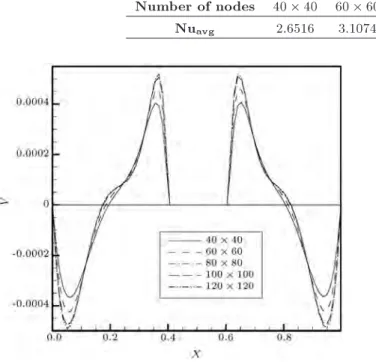
Table 3. Average Nusselt number of the square cavity for dierent uniform grids, h=H = 0:2, ' = 0:015 and Ra = 106.
Number of nodes 40 40 60 60 80 80 100 100 120 120 Nuavg 2.6516 3.1074 3.4112 3.4127 3.4130
Figure 3. Vertical velocity component along the horizontal centerline of the cavity (y = H=2) for dierent uniform grids, h=H = 0:2, ' = 0:015, and Ra = 106.
simulations are performed for h=H = 0:2, Ra = 106,
and ' = 0:015. Five dierent uniform grids, namely, 40 40, 60 60, 80 80, 100 100 and 120 120, are employed for the numerical calculations.
Figure 3 shows the vertical velocity component along the horizontal centerline of the cavity (y = H=2, Figure 1) for these grids. The results for the average Nusselt number of the cavity for the above grids are also presented in Table 3. It is observed from Figure 3 and Table 3 that an 80 80 uniform grid is suciently ne to capture the details of the velocity and temperature variations in the boundary layers adjacent to the walls. Therefore, based on these results, an 80 80 uniform grid is employed to perform all subsequent numerical calculations. Moreover, in the numerical calculations, the convergence criterion for the temperature, pressure, and velocity is taken to be:
Error =
m
P
j=1 n
P
i=1j
t+1 tj m
P
j=1 n
P
i=1j
t+1j 10
7; (25)
where m and n are the number of grid points in the x and y directions, respectively, is any of the computed eld variables, and t is the iteration number.
4. Results and discussion
In order to understand the ow and heat transfer characteristics of the considered problem, six dierent
Table 4. Coordinates of the center of the heat source for the six considered cases.
Case number x-coordinate y-coordinate
I H=2 H=2
II H=2 H=4
III H=4 H=4
IV H=4 H=2
V H=4 3H=4
VI H=2 3H=4
Figure 4. Streamlines and isotherms in the cavity lled with TiO2-water for case I: (a) Streamlines; and (b)
isotherms.
cases, cases I through VI, as far as the position of the heat source inside the cavity is concerned, are considered. The coordinates of the center of the heat source for the six considered cases are given in Table 4. In all the following numerical results, the ratio of the size of the heat source to that of the cavity, h=H, is taken as 0.2, and the cavity is lled with the TiO2
-water nanouid. The simulations are performed for a range of Rayleigh numbers from 103 to 106, and for
three volume fractions of the nanoparticles, namely, 0 (pure water), 0.015 and 0.03.
Figure 4(a) and (b) show the streamlines and the isotherms inside the cavity for case I, respectively. The results in these gures are presented for the volume fraction of the nanoparticles, ' = 0 and 0.03, and
for dierent Rayleigh numbers. The uid is heated by the left and right side walls of the heat source and expands as it moves upwards. Subsequently, along the downowing branch of the cycle, the uid is cooled by the cold walls of the cavity, and compressed as it reaches the depth of the cavity. Hence, as Fig-ure 4(a) shows, two counter-rotating eddies, clockwise and a counterclockwise, develop in the right and left halves of the space between the heat source and the cavity. For low Rayleigh numbers, i.e. conduction-dominated uid ow and heat transfer, these eddies, symmetrically-located, with respect to the centerlines of the cavity (Figure 4(a) for Ra = 103), are quite
weak. With increasing Rayleigh number, the two main eddies strengthen as their centers shift towards the top wall of the cavity (Figure 4(a) for Ra 104); however,
they constantly remain symmetric with respect to the vertical centerline of the cavity. For high enough Rayleigh numbers (Ra = 106 in Figure 4(a)), the
hot bottom wall of the heat source resists the natural convection in the bottom of the cavity, resulting in a relatively stagnant region.
The corresponding isotherms inside the cavity for case I are shown in Figure 4(b). For low Rayleigh numbers (Figure 4(b) for Ra = 103), the isotherms
are almost evenly-distributed in the space between the heat source and the walls of the cavity. Increasing the Rayleigh number gives rise to the formation of thermal boundary layers around the heat source, as well as close to the top and upper portions of the side walls of the cavity, bringing about greater heat transfer rates in these regions (Figure 4(b) for Ra 105). Meanwhile,
the isotherms, similar to the streamlines, always remain symmetric with respect to the vertical centerline of the cavity. Moreover, for high Rayleigh numbers, the core of the two main eddies is relatively stagnant and thermally stratied, and the stagnant region under the heat source is nearly isothermal, with a minimum heat transfer rate (Figure 4(b) for Ra 105).
The streamlines and the isotherms inside the cavity for case II are shown in Figure 5(a) and (b), respectively. As observed from Figure 5(a), two main counter-rotating eddies, which are symmetric only with respect to the vertical centerline of the cavity, form inside the cavity. The center of these eddies moves upwards as the natural convection strengthens with increasing the Rayleigh number. As the heat source is moved towards the bottom of the cavity, the stagnant region under its bottom wall shrinks (Figure 5(a) for Ra 105), improving the heat transfer rate there. As
far as the isotherms are concerned, for low Rayleigh numbers, they are densely distributed in the narrow space between the bottom of the heat source and the cavity's bottom wall, and thinly scattered above the heat source, resulting in high and low temperature gradients under and above the heat source, respectively
Figure 5. Streamlines and isotherms in the cavity lled with TiO2-water for case II: (a) Streamlines; and (b)
isotherms.
(Figure 5(b) for Ra 104). For high Rayleigh
numbers, thermal boundary layers form around the heat source and close to the top wall of the cavity, indicating high heat transfer rates in these regions. Moreover, large regions close to the center of the main eddies remain nearly isothermal (Figure 5(b) for Ra = 106).
Figure 6(a) and (b) show the streamlines and the isotherms inside the cavity for case III. By moving the heat source towards the left bottom corner of the cavity, a main clockwise vortex develops due to the natural convection in the relatively large space to the right of the heat source. Another smaller counterclockwise vortex forms in the left portion of the cavity above the heat source (Figure 6(a)). With increasing the Rayleigh number, the natural convection above the heat source intensies, and the counterclockwise eddy enlarges. Meanwhile, the narrow regions to the left and under the bottom of the heat source always remain relatively stagnant (Figure 6(a)). As far as the isotherms are concerned, the above-mentioned narrow regions are dominated by heat conduction, even for high Rayleigh numbers (Figure 6(b)). Moreover, as the Rayleigh number increases, thermal boundary layers form close to the top and left walls of the cavity with high temperature gradient toward the left and close to the top of the cavity's top and left walls, respectively, giving rise to high heat transfer rates in these regions. (Figure 6(b) for Ra = 106).
The streamlines and the isotherms inside the cavity for case IV are presented in Figure 7(a) and
Figure 6. Streamlines and isotherms in the cavity lled with TiO2-water for case III: (a) Streamlines; and (b)
isotherms.
Figure 7. Streamlines and isotherms in the cavity lled with TiO2-water for case IV: (a) Streamlines; and (b)
isotherms.
(b), respectively. Similar to the previous case, a main clockwise vortex develops to the right of the heat source, in this case. For low Rayleigh numbers, this vortex is symmetric, with respect to the horizontal centerline of the cavity (Figure 7(a) for Ra = 103).
Two smaller eddies also form above and under the
Figure 8. Streamlines and isotherms in the cavity lled with TiO2-water for case V: (a) Streamlines; and (b)
isotherms.
heat source in this case. As the natural convection strengthens with increasing the Rayleigh number, the center of the main eddy shifts toward the top wall of the cavity (Figure 7(a) for Ra = 106). Besides, the
uid ow in the top small eddy intensies, while the eddy under the heat source vanishes as a result of the heat source resisting the natural convection close to the bottom left corner of the cavity (Figure 7(a) for Ra = 106). Moreover, the former eddy shrinks as the
volume fraction of the nanoparticles and, in turn, the nanouid viscosity increase. As far as the isotherms are concerned, the highest temperature gradient occurs in the boundary layer close to the top wall of the cavity above the heat source for Ra = 106. Furthermore, for
high Rayleigh numbers, the heat transfer rate in the stagnant region above the bottom wall of the cavity is negligible (Figure 7(b) for Ra 105).
Figure 8(a) and (b) show the streamlines and the isotherms inside the cavity for case V. Similar to the previous case, here, a main clockwise vortex develops to the right of the heat source due to natural convection. Also, a smaller counterclockwise eddy forms in the left lower portion of the cavity (Figure 8(a)). As the natural convection strengthens, the centers of these eddies shift toward the top wall of the cavity, con-sequently, a relatively stagnant and isothermal region with negligible heat transfer rate emerges in the bottom of the cavity (Figure 8(a) and (b) for Ra = 106).
Moreover, the counterclockwise eddy weakens as the Rayleigh number increases and, even more eminently, as both the Rayleigh number and the volume fraction of
Figure 9. Streamlines and isotherms in the cavity lled with TiO2-water for case VI: (a) Streamlines; and (b)
isotherms.
the nanoparticles increase. For low Rayleigh numbers, the isotherms are concentrated in the narrow spaces above and to the left of the heat source, resulting in high heat transfer rates there (Figure 8(b) for Ra 104). As the Rayleigh number increases, thermal
boundary layers with high temperature gradients and relatively large heat transfer rates develop along the cavity's top wall above the heat source (Figure 8(b) for Ra 105).
The streamlines and the isotherms for case VI are shown in Figure 9(a) and (b), respectively. Similar to case I, two counter-rotating vortices are present inside the cavity in this case. However, two smaller counter-rotating eddies, similar to the Bernard cells, develop in the gap between the top walls of the heat source and the cavity for Ra = 106, in this case
(Figure 9(a)). These latter eddies contract as the volume fraction of the nanoparticles and, in turn, the eective viscosity of the nanouid increase. As far as the isotherms are concerned, for low Rayleigh numbers, high temperature gradients are observed in the gap above the heat source (Figure 9(b) for Ra 104).
For the convection-dominated heat transfer regime, thermal boundary layers develop along the cavity's top wall, resulting in a high rate of heat transfer there, while the lower portion of the cavity is nearly isothermal with negligible heat transfer (Figure 9(b) for Ra 105).
Figure 10 shows the Nusselt number distributions along the walls of the cavity for the six considered cases. The results are presented for Ra = 103 and for
three dierent volume fractions of the nanoparticles, namely, 0.0 (pure uid), 0.015 and 0.03. For Ra = 103,
the heat transfer occurs mainly through conduction. It is seen from this gure that, for case I, where the heat source is placed at the middle of the cavity, each cavity wall has nearly the same Nusselt number distribution with a local maximum at its middle. As the volume fraction of the nanoparticles and, in turn, the thermal conductivity of the nanouid increase, the Nusselt number rises, implying enhanced heat transfer. For the other cases shown in this gure, the maximum local Nusselt number occurs along the walls having minimum distance from the heat source, while the Nusselt number is quite low along the remaining walls. Moreover, the local maxima of Nusselt number for cases II through VI are signicantly higher than those of case I. Increasing the volume fraction of the nanoparticles for cases II through VI increases the local maxima of the Nusselt number signicantly (Figure 10).
The Nusselt number distributions along the cavity walls for Ra = 106 and for the six considered cases
are presented in Figure 11. The results in this gure are for three dierent volume fractions of the nanoparticles, namely, 0.0, 0.015 and 0.03. As seen from this gure, for case I, contrary to the results of Figure 10, the maximum local Nusselt number occurs at the middle of the cavity's top wall, while the Nusselt number is quite low along its bottom wall. Moreover, the heat transfer enhancement, with increasing the volume fraction of the nanoparticles, is marginal in this convection-dominated heat transfer regime, as a result of the nanouid becoming more viscous, by raising the nanoparticles volume fraction. For case II, similar to the previous case, the local Nusselt number has a maximum at the middle of the cavity's top wall, whose magnitude, nevertheless, is smaller compared to that of case I, due to the eddies being weaker in the latter case. For cases II through V, the maximum local Nusselt number occurs in the thermal boundary layers towards the left portion of the top wall of the cavity, where the temperature gradient is relatively high (Figure 11). Moreover, the highest local Nusselt number among these cases belongs to case V, for which the heat source has the smallest distance from the cavity's top wall. For case VI, the Nusselt number has two local maxima along the top wall of the cavity, which are symmetrically-located, with respect to the cavity's vertical centerline, with the Nusselt number decreasing substantially between them (Figure 11). This particular distribution of Nusselt number is attributed to the formation of two small eddies above the top wall of the heat source, in this case (Figure 9(a)).
Figure 12 shows the variations of the aver-age Nusselt number of the cavity for the six
con-Figure 10. local Nusselt number along the cold walls of the cavity for the six dierent locations of the heat source, Ra = 103, and ' = 0:0, 0.015, and 0.03.
sidered cases, with respect to the volume fraction of the nanoparticles for dierent Rayleigh num-bers.
It is observed from the gure that for conduction-dominated heat transfer regime, Ra = 103, the average
Nusselt number for all the considered cases signicantly increases with increasing the volume fraction of the nanoparticles, a characteristic which is attributed to the thermal conductivity enhancement by increasing the volume fraction of the nanoparticles. Moreover, as the geometry and the boundary conditions for cases III and V are alike, as far as conduction heat transfer is concerned, their average Nusselt numbers should be the same for the entire range of the considered volume fraction of the nanoparticles (Figure 12 for Ra = 103).
By the same token, cases II, IV, and VI ought to have similar average Nusselt number, as demonstrated in Figure 12, for Ra = 103. The maximum heat transfer
rate belongs to either of cases III or V, where the heat source is located close to two of the cavity walls, while the minimum heat transfer rate pertains to case I, with the heat source at the center of the cavity (Figure 12 for Ra = 103).
With increasing the Rayleigh number, the average
Nusselt number for case V reduces drastically, com-pared to that of case III, due to signicant blockage eects in the narrow gaps between the heat source and the top and left walls of the cavity for the former case (Figure 12 for Ra 104). In fact, the minimum average
Nusselt number for Ra = 106pertains to case V. As far
as cases II, IV, and VI are concerned, the average Nus-selt number for case II increases moderately, compared to that of case IV, with increasing the Rayleigh number. However, for case VI, due to the substantial blockage eect in the narrow gap between the top walls of the heat source and cavity, the average Nusselt number decreases signicantly, compared to that of case IV, as natural convection becomes dominant (Figure 12 for Ra 106). The maximum average Nusselt number for
the convection-dominated heat transfer regime pertains to case II, with a minor blockage eect (Figure 12 for Ra = 106). Moreover, in general, for Ra 104,
the average Nusselt number increases with increasing the volume fraction of the nanoparticles for all the cases, albeit with lower rates, compared to those for Ra = 104, due to the dominant role played by the
viscosity of the nanouid in high Rayleigh number ows.
Figure 11. local Nusselt number along the cold walls of the cavity for the six dierent locations of the heat source, Ra = 106, and ' = 0:0, 0.015, and 0.0.
Figure 12. Variations of the average Nusselt number of the cavity with respect to the volume fraction of the nanoparticles for dierent Rayleigh numbers.
5. Conclusions
Buoyancy-driven uid ow and heat transfer of TiO2
-water nanouid, due to the square-shaped heat source inside the square cavity, are simulated numerically. The nite volume method, together with the SIM-PLER algorithm, is implemented to solve the governing equations written in terms of the primitive variables. The numerical procedure is veried via simulating the natural convection in a partially-heated square cavity lled with Cu-water nanouid.
The eects of the location of the heat source inside the cavity, the Rayleigh number, and the TiO2
volume fraction, on the uid ow and heat transform are investigated by conducting a parametric study. As far as the position of the heat source inside the cavity is concerned, six dierent cases, I through VI, are considered. The results, in general, show that the heat source location is eminently an eective parameter controlling the shape and size of eddies formed inside the cavity and, subsequently, the heat transfer rate. For the conduction-dominated heat transfer regime, Ra = 103, the maximum heat transfer rate is achieved,
irrespective of the volume fraction of the nanoparticles, by placing the heat source close to the cavity corners (cases III and V), while the lowest rate heat transfer pertains to case I with the heat source at the center of the cavity. For convection-dominated heat transfer regime, Ra = 106, the highest rate of heat transfer
is accomplished by placing the heat source near the corner of the cavity's bottom wall for the considered range of the volume fraction of the nanoparticles (case II). On the other hand, for the same Rayleigh number, case V, with the heat source positioned towards the top left corner of the cavity, has the lowest Nusselt number, irrespective of the volume fraction of the nanoparticles.
Finally, the results for the local and average Nusselt numbers demonstrate that natural convection heat transfer is much improved in the presence of TiO2
nanoparticles. Nomenclature cp Heat capacity
d Diameter, m
g Gravitational acceleration, m/s2
h Heat source height, m H Cavity height, m
k Thermal conductivity, W/m-K M Molecular weight
N Avogadro number Nu Nusselt number p Pressure, kg/m-s2
P Dimensionless pressure Pr Prandtl number Ra Rayleigh number Re Reynolds number
s Special coordinate system, m S Dimensionless special coordinate
system
T Temperature, K
u; v Velocity components, m/s
U; V Dimensionless velocity components xy Cartesian coordinates, m
X; Y Dimensionless Cartesian coordinates Greek letters
Thermal diusivity, m2/s
Thermal expansion coecient, 1/K Viscosity, kg/m-s
v Kinematics viscosity, m2/s
Dimensionless temperature Density, kg/m3
' Volume fraction of nanoparticles Subscript
avg Average
c Cold
f Fluid
h Hot
nf Nanouid p Particle References
1. Khanafer, K., Vafai, K. and Lightstone, M. \Buoyancy-driven heat transfer enhancement in a two-dimensional enclosure utilizing nanouid", Int. J. Heat Mass Transf., 46, pp. 3639-3653 (2003).
2. Abu-Nada, E., Masoud, Z. and Hijazi, A. \Natural convection heat transfer enhancement in horizontal concentric annuli using nanouids", Int. Comm. Heat Mass Transf., 35, pp. 657-665 (2008).
3. Santra, A.K., Sen, S. and Chakraborty, N. \Study of heat transfer augmentation in a dierentially heated square cavity using copper-water nanouid", Int. J. Therm. Sci., 47, pp. 1113-1122 (2008).
4. Oztop, H.F. and Abu-Nada, E. \Numerical study of natural convection in partially heated rectangular enclosures lled with nanouids", Int. J. Heat Fluid Flow, 29, pp. 1326-1336 (2008).
5. Abu-nada, E. and Oztop, H. \Eect of inclination angle on natural convection in enclosures lled with
Cu-water nanouid", Int. J. Heat Fluid Flow, 30, pp. 669-678 (2009).
6. Aminossadati, S.M. and Ghasemi, B. \Natural convec-tion cooling of a localized heat source at the bottom of a nanouid-lled enclosure", Eur. J. Mech. B/Fluids, 28, pp. 630-640 (2009).
7. Ghasemi, B. and Aminossadati, S.M. \Periodic natural convection in a nanouid-lled enclosure with oscillat-ing heat ux", Int. J. Therm. Sci., 49, pp. 1-9 (2010).
8. Oztop, H.F., Abu-Nada, E., Varol, Y. and Al-Salem, K. \Computational analysis of non-isothermal temper-ature distribution on natural convection in nanouid lled enclosures", Superlattic. Microstruct., 49, pp. 453-467 (2011).
9. Sheikhzadeh, G.A., Arefmanesh, A. and Mahmoodi, M. \Numerical study of natural convection in a dierentially-heated rectangular cavity lled with TiO2-water nanouid", J. Nano Res., 13, pp. 75-80 (2011).
10. Alloui, Z., Vasseur, P. and Reggio, M. \Natural con-vection of nanouids in a shallow cavity heated from below", International Journal of Thermal Sciences, 50, pp. 385-393 (2011).
11. Aminossadati, S.M. and Ghasemi, B. \Natural convec-tion of water-CuO nanouid in a cavity with two pairs of heat source-sink", International Communications in Heat and Mass Transfer, 38, pp. 672-678 (2011).
12. Nasrin, R. and Parvin, S. \Investigation of buoyancy-driven ow and heat transfer in a trapezoidal cavity lled with water-Cu nanouid", International Commu-nications in Heat and Mass Transfer, 39, pp. 270-274 (2012).
13. Nikfar, M. and Mahmoodi, M. \Meshless local Petrov-Galerkin analysis of free convection of nanouid in a cavity with wavy side walls", Engineering Analysis with Boundary Elements, 36, pp. 433-445 (2012).
14. Mahmoudi, A.H., Shahi, M., Honarbakhsh Raouf, A. and Ghasemian, A. \Numerical study of natural convection cooling of horizontal heat source mounted in a square cavity lled with nanouid", International Communications in Heat and Mass Transfer, 37, pp. 1135-1141 (2010).
15. Mahmoudi, A.H., Shahi, M., Moheb Shahedin, A. and Hemati, N. \Numerical modeling of natural convection in an open cavity with two vertical thin heat sources subjected to a nanouid", International Communi-cations in Heat and Mass Transfer, 38, pp. 110-118 (2011).
16. Cho, C., Yau, H. and Chen, Ch. \Enhancement of natural convection heat transfer in a U-shaped cavity lled with Al2O3-water nanouid", Thermal Science, 16, pp. 1317-1323 (2012).
17. Mahmoodi, M. \Numerical simulation of free convec-tion of a nanouid in L-shaped cavities",
Interna-tional Journal of Thermal Sciences, 50, pp. 1731-1740 (2011).
18. Mahmoodi, M. and Hashemi, S.M. \Numerical study of natural convection of a nanouid in C-shaped en-closures", International Journal of Thermal Sciences, 55, pp. 76-89 (2012).
19. Dehnavi, R. and Rezvani, A. \Numerical investigation of natural convection heat transfer of nanouids in a shaped cavity", Superlattices and Microstructures, 52, pp. 312-325 (2012).
20. Mahmoodi, M. \Numerical simulation of free convec-tion of nanouid in a square cavity with an inside heater", International Journal of Thermal Sciences, 50, pp. 2161-2175 (2011).
21. Shahi, M., Mahmoudi, A.H. and Talebi, F. \Entropy generation due to natural convection cooling of a horizontal heat source mounted inside a square cavity lled with nanouid", Heat Transfer Research, 43, pp. 19-46 (2012).
22. Sheikhzadeh, G.A., Nikfar, M. and Fattahi, A. \Nu-merical study of natural convection and entropy gen-eration of Cu-water nanouid around an obstacle in a cavity", Journal of Mechanical Science and Technol-ogy, 26, pp. 3347-3356 (2012).
23. Mahmoodi, M. and Mazrouei Sebdani, S. \Natural convection in a square cavity containing a nanouid and an adiabatic square block at the center", Super-lattices and Microstructures, 52, pp. 261-275 (2012).
24. Aminossadati, S.M. and Ghasemi, B. \Conjugate nat-ural convection in an inclined nanouid-lled enclo-sure", International Journal of Numerical Methods for Heat & Fluid Flow, 22, pp. 403-423 (2012).
25. Arefmanesh, A., Amini, M., Mahmoodi, M. and Naja, M. \Buoyancy-driven heat transfer analysis in two-square duct annuli lled with a nanouid", European J. of Mechanics - B/Fluids, 33, pp. 95-104 (2012).
26. Habibi Matin, M. and Pop, I. \Natural convection ow and heat transfer in an eccentric annulus lled by Copper nanouid", International Journal of Heat and Mass Transfer, 61, pp. 353-364 (2013).
27. Bejan, A. Convection Heat Transfer, John Wiley & Sons, Inc., Hoboken, New Jersey, USA (2004).
28. Corcione, M. \Empirical correlating equations for predicting the eective thermal conductivity and dy-namic viscosity of nanouids", Energy Conversion and Management, 52, pp. 789-793 (2011).
29. Patankar, S.V. Numerical Heat Transfer and Fluid Flow, Hemisphere Publishing Corporation, Taylor and Francis Group, New York (1980).
Biographies
Ali Arefmanesh received his BS degree from Sharif University of Technology, Tehran, Iran, in 1980, and
MS and PhD degrees in 1987 and 1992, respectively, from the University of Delaware, Newark, USA. He is currently Associate Professor in the Department of Mechanical Engineering at The University of Kashan, Iran. His current research interests are computational uid dynamics, numerical simulation of uid ow and heat transfer of nanouids, and meshless numerical methods.
Mostafa Mahmoodi received his BS degree in Mechanical Engineering (Thermo Fluids) from Yazd University, Yazd, Iran, in 2007, his MS degree in Mechanical Engineering (Energy Conversion) from the
University of Kashan, Iran, in 2011, and is currently a PhD degree candidate in Mechanical Engineer-ing at Amirkabir University of Technology, Tehran, Iran. His main areas of research are ow around cubic buildings and natural convection ow simula-tion.
Mehdi Nikfar received his MS degree from Kashan University, Iran, in 2009, and is currently working towards his PhD degree in K.N. Toosi University of Technology, Tehran, Iran. His main research interests are numerical simulation of natural convection ow, meshless methods and CFD.