1. Introduction
Electrical trees have been considered to be, in their early stage of development, the result of mechanical shock waves caused by local intrinsic breakdown of the insulating materials.[1,2]. The same has been confirmed by Hiroaka .V [7]. It follows from this, and has been proven by the results and that of the Auckland [3], that the strain surrounding a barrier effects the progress of the trees as the barrier is approached. Like wise, the strength of the adhesive bound between barrier and surrounding resin also effects the ways in which channels progress in the presence of the barrier [4]. Trees tend to grow in the direction of the applied field. The work done so far has been concerned with the interaction between barriers. The particles, films or fabrics were laying perpendicular to the axis of symmetry of the field. In practice barrier rarely disposed at right angle to the applied field. Thus the shock waves which produce the trees may impinge upon a barrier at many angles with respect to the interface between barrier and surrounding matrix as shown in figure 1.
Hypodermic needle Axis of symmetry of the field
Barrier at 00 Barrier at 450 Barrier at 900 900 450
Fig. 1: Disposition of barrier
It has been shown by [5, 6 ] that stain effects the growth of electrical trees. The barrier disposed at different angle produces different pattern of strain. The work to be
described studies the possible effects which angle might have on the progress of trees in the presence of barriers.
2. Materials
The materials used in this investigation were thermosetting polyester resin as matrix, glass of 1mm thickness, PTFE and Melinex as barriers. The criteria of selection of these materials was, as indicated above, based of their work of adhesion with polyester resin. Glass has high work of adhesion, Melinex has medium one while PTFE has low work of adhesion with resin as shown in Table 1.
Table 1
Materials Y1= mj-m-2
Kc= KN-m-3/2
WA
mJ-m-2
Tc
C0
Glass 560 400 303.5 827
PTFE 11.1 850 42.67 327
Melinex (PET)
43.9 1800 84.85 255
Matrix: Polyester resin Surface energy Y2 =41mj-m-2
Y Surface energy WA= Work of adhesion
Kc = Fracture toughness Tc = Melting point
The resin was supplied by Scott Bader and is known as clear casting resin C. This resin was chosen because of its ease of handling, rapid curing, good physical and electrical properties, dimensional stability and optical quality.
Effect of Barrier Angle
on Tree Growth
in Solid Insulation
1
A. Rashid,
1Mohammad Ali,
2Suhail Aftab Qureshi
1
COMSATS Institute of Information
Technology,
Abbottabad
2
University of Engineering and Technology, Lahore
Abstract
In this research work the effect of barrier angle on tree resistance has been revealed in clear polyester resin. The work to be described studies the possible effect with angular displacement might have the progress of trees in the presence of barrier. The barriers were cast at 00, 450 and 900 with respect to axis of symmetry of the field. The barrier selected for this study were glass and Melinex and PTFE castled in clear polyester resin C. The resin C was selected due to its transparent properties so optical observation and photographic record is possible. The selection of the materials was based on their work of adhesion. These materials were employed in a clear polyester resin thus making a barrier. The specimens, whatever the type (angle00, 450 and 900) were tested in batches of 20 to establish their life time. This was measured in term of number of cycle to breakdown. Hypodermic needle was used as H.V electrode and 28kV A.C was the test voltage. The separation between electrodes is 2mm. The result shows that barriers offer higher resistance when disposed at 900 with respect to field.
3. Specimen manufacture:
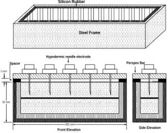
The specimens were made from resin containing 1% hardener by volume with a thin layer of particles lying between point and plane electrodes. Hypodermic needles were used as point electrode because they are sharp enough to support tree growth, cheap reproducible and readily available. The specimens were cast in strips in a silicone mould supported in a steel frame as shown in figure 2. The walls of the mould were lined on the inside with Melinex which ensured that the sides of the finished product had flat polished surfaces facilitating optical observation.
Hypodermic needle electrode Spacer
Spacer
350 mm 50 mm
Front Elevation
1 mm
Side Elevation Perspex Bar
Steel Frame Silicon Rubber
Fig. 2: Specimen manufacture method
Fig. 3: Specimen manufacture method when
barrier disposed at 45
0Consider first the production of the specimens containing glass containing barrier at zero degree with respect to the axis of symmetry of the field between the electrode. Basically Persrpex strip cut at required angle and then barrier placed and held firmly with perpex piece as shown in figure 3.Hypodermic needles were used as point electrode because they are sharp enough to support tree growth, cheep reproducible and readily available. High voltage 28kV A.C, 50Hz was applied in the form of burst through counter which counts the number of cycles applied to the specimen.
1mm
1.mm High Voltage needle electrode
Barrier
Polyester resin
Fig. 4(a): Point plan Specimen containing barrier
4. Polariscope:
Growth of trees within the specimens was observed using a Polariscope. It is a device which reveals different strain pattern within the materials, such as polyester, that exhibits the photo electric effect. The use of Polariscope was of the crossed circular type.
Counter IC
Comparator
Display
Isolator
TW Thumbwheel Switch
V 240 VAC
TR HT
S
Low Voltage
T/F Squarer I/P
O/P
Fig. 4(b): Block diagram High voltage equipment
5. High Voltage Test equipment:
The high voltage test equipment used is illustrated in Figure 4(b) It consisted of a single phase step up transformer 240V/30kV, 1.5kVA, 50Hz supplied from a mains driven variable ratio transformer variac via a triac TR activated by a control unit. The auto transformer was used to control the magnitude of the voltage applied whilst the control unit regulated the number of cycles applied, in the range of 1 to 9999.The control unit, which was purpose built by the
authors, is basically a counter. A block diagram showing the major components is shown in figure 4(b).
6. Experimental Procedure
A group of 20 identical specimens were tested for each type of barrier. Each specimen was clamped between brass electrodes in the test cell shown in Figure 5. The cell was then filled with pentane to suppress extraneous discharges.
Specimen Spring
Fig. 5: Test Cell
28kV rms was selected to be the test voltage, because it produced intrinsic breakdown at the tip of the hypodermic needle leading to easily observed and repeatable tree growth in the dielectric. Voltage was applied in bursts, for a prescribed number of Cycles determined by the control unit until the specimen broke down. Following each application of voltage, the inter-electrode gap was inspected in the Polariscope for tree growth. Photographs were taken at various stages of growth using a camera mounted on the Polariscope eye piece.
7. Results and Discussion
The specimens, whatever the type and angle of barrier, were tested in batches of 20 to establish their life time. This was, as before, measured in terms of the number of cycle of the test voltage to cause breakdown by treeing. The test procedure was same as described above and test voltage 28kV applied in bursts using a triac controlled transformer. The specimens were inspected under a microscope, following each application of voltage, to observe there growth.
The first specimens tested were those containing no barrier. They had an average life time of 1400 cycle with a standard deviation of 560. The presence of polyester barrier increased the life time compared with no barrier. But angular position had no significant effect, as indicated by application of student’s t test which showed that the difference in the mean values recorded for 00 and 45 0 was not significant. Similarly there was no significance to be
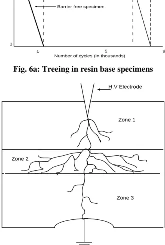
assigned to the difference in the mean values recorded for the 900 and 450 cases. Observation of the three growth associated with each angle did indicate some difference of the tree form however. Thus, the channels produced in the 450 case were a little more profuse above the barrier than in the case of barriers disposed at 900 to the field. In the case of barriers aligned at 00 the growth was confined to the barriers region. Resin based specimens were tested to comparison purposes to other barrier. The observation of the tree growth in the presence of resin barriers are summarised in figure 6a for the horizontal barrier. This shows how the rate of tree growth changed as barrier approached. Referred to figure 6a treeing in the presence of the barrier is divided into three zone. Zone 1 where the treeing begin to grows toward the barrier. The tree is contained by the barrier in zone 2 and its growth toward electrode contained in zone 3 as shown in Figure 6b
Zone 1
Zone 2 Zone 3
Barrier effect
Barrier free specimen
Number of cycles (in thousands) Tree
length (mm)
0
3
1 5 9
Fig. 6a: Treeing in resin base specimens
Zone 1
Zone 2
Zone 3 H.V Electrode
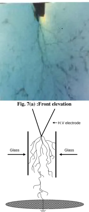
The second set of specimens tested were those containing glass barriers at zero degree. The results are summarized in table 2 Strain was induced by the glass barriers as is apparent from the background coloration in Figure 7. Figure 7 (a) shows the front view looking through the glass . It was impossible to obtain a clear image of the growth looking side ways along the interface layer of the resin. Sectioning of the specimens required to do so caused destruction of the glass resin interface.
Observations that could be made indicated the pattern of development as sketched in Figure 7(b). This shows that the glass has no direct contact with the tree growth, which splits into many branches indicating the presence of compressive strain around the strips of glass.
Fig. 7(a) :Front elevation
Glass Glass
H.V electrode
Fig. 7(b): side elevation
Figure 7 Tree growth in a specimen containing a glass barrier at 00.
The mean life of the specimens containing glass aligned at 00 was increased by a factor of 6 compared with the resin barriers specimens aligned at 00 and 25 times greater than barrier free specimens.
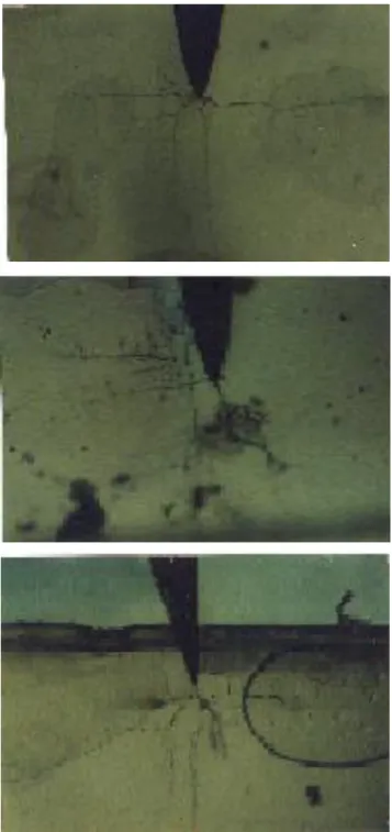
The specimens with the glass inclined at 450 to the axis of the field offered much more resistance than those at 00 as is clear from Table.1. Tree initiation time and the degree of strain induced was the same as for the glass barrier set at 00 but growth was much slower tree preferred to grow sideways with many branches containing numerous tiny channels. Tree pattern shown in Figure 8 when barrier disposed at 450
Fig. 8: Tree growth in a specimen containing a
glass barrier at 45
0Tree growth was along the resin-barrier interface but no touching the barriers itself .In none of the 20 specimens tested did trees penetrate the glass barriers.
Table 2: Summary of test results
Barrier type Angle with field
Average Cycle to Bd
S.D
Resin 00 5657 3160
Resin 450 7109 3170
Resin 900 8850 5981
Glass 00 36065 22261
Glass 450 93150 21280
Glass 900 12400 3555
Melinex 00 5160 3288
Melinex 450 46596 32462
Melinex 900 82692 21233
PTFE 00 1370 602
PTFE 450 12250 5374
The specimens containing glass barrier at 900 to the axis of the point-plan field had shorter life time than 0o and 45o counterparts. Strain retarded and diffused the growth as barrier was approached, subsequent fracture of the glass providing an easy path for growth through to the lower side of the glass. The pattern of tree growth is shown in Figure 9.
Fig. 9: Tree growth in a specimen containing glass
barrier at 90
0In the case of of Melinex and PTFE,, the life time of the specimen film aligned to the 00 with respect to the field was less than the resin and glass at 00. It is much less when compared with the latter, the reason being that there is less compression in the specimens containing Melinex and PTFE compared with glass.
The reduced compression in these specimens follows from poor work of adhesion with the surrounding resin being lowest in the case of PTFE. Poor work of adhesion also lead easy debonding between the barrier and resin. The tree channels were forced to concentrate along the weak interface probably due to lack of compression and it is this tendency which led to premature failure of the PTFE specimens.
Specimens with Melinex barriers inclined at 450 to the field had life times approximately one half of their glass counterparts whilst the life of the PTFE barrier inclined at 450 was approximately one tenth that of the glass equivalent. Debonding occurred when the tree reached the film barrier in both Melinex and PTFE cases. Considering first the Melinex, debonding let to the spreading of tree growth across the Melinex-polyester interface. Eventually the Melinex specimens broke down through the barrier at point close to the earth electrode. The spreading effect accompanying the debonding served to retard progress to this point.
Fig.10 Pattern of Tree growth in a specimen
containing melinex barrier at 45
0Specimens containing Melinex arranged at 90o to the axis of the field exhibited life time similar to that of glass, tree growth being retorted by delaminating and the creation of new trees at the resin interface as explained and shown previously. In the caser of PTFE films the life of the specimens at 90o was greater than for glass at 90o. This was because the initial channels debonded the P.T.F.E and did not penetrate presumably because of its high melting point.
Development was confined to broadening of signal channels leading in most cases to puncturing of the barriers. In some instances broadening of the incident channels was also accompanied by surface tracking to the failure to the specimens over the edge of the film.
8. Conclusion:
The work described demonstrate that growth of tree and pattern depend upon the orientation of the barrier and work of adhesion of barrier with matrix. Barrier offer high resistance to tree growth when disposed at 450 provided barrier material has high work of adhesion.
9. References:
[1] Varlow B.R and Makin G.J., “ Electrical Treeing in Mechanically Prestressed Insulation”, IEEE Transection on Dielectrics and Electrical Insulation, Vol. 7 No 6 December, 2000.
[2] Auckland D.W,. McNcol A., Varlow B.R., “Development of Strain in Solid Dielectric Due to Vibrational Electrostatic Forces”, IEE Proc., Vol 28, Part A, No 3, 1990. PP 1608-1613.
[3] Auckland D.W, Rashid A., and Varlow B.R., “Effect of Barrier on Tree Growth in Solid Insulation” IEE Proc. Sci.Meas Technol, Vol 142, No 4, July, 1995. [4] Auckland D W, A Rashid “The Influence of Particular
Barrier on Treeing in Polyester Resin” 4th International Conference on Conduction and Breakdown in Solid Dielectric. Sertri Levanta, Italy June 1992.
[5] Rashid A, Shuakat S.F .,“Effect of Strain on the Lifetime of Filled Insulation” World Applied Science Journal 7(1), 86-93,2009 ISSN 1818-4-4952.
[6] Arbab M.N., and Auckland D.W “The Influence of Vibration on the Initiation of Trees in Dielectric”, IEE Proc. Part A, Vol.133, No 9, 1986, PP 618-622. [7] Hiroaka V., Takanori A., “Treeing Phenomena in EVA
with various Barrier Films of Polymers” IEEE 7th International Conference on Solid Dielectric, June 25-29, 2001 Eindhoven, The Natherlands.