The Search For Photon-Induced Metal Hydride
Formation and Modeling of Multi-Step
Multi-Electron Electrocatalytic Reactions at the
Rotating Disc Electrode
by
Cole Gruninger
Submitted to the Department of Chemistry
UNIVERSITY OF NORTH CAROLINA AT CHAPEL HILL
May 2020
Cole Gruninger . . . .
Department of Chemistry
May 1, 2020
Certified by . . . .
Jillian L. Dempsey
Associate Professor
Thesis Supervisor
Acknowledgments
This work is the culmination of three years of support, guidance, and inspiration at the University of North Carolina at Chapel Hill. First and foremost, I am deeply indebted to Dr. Jillian Dempsey, who took me on as an undergraduate researcher after I transferred from the University of North Carolina at Wilmington. With neither knowledge of my academic background nor my earlier grades, Jill believed in me due to my passion for chemistry, and that has meant the world. After three years, I have learned so much under her mentorship: the fundamentals of electrochemistry and proton-coupled electron transfer, group theory, and spectroscopy. Additionally, I have been inspired by her example in holding and presenting myself as a researcher, scientist, and academic. Every time I think about my time in the Dempsey Group -the friendships, collaboration, and passion for excellence in research - a smile comes to my face. It has been by far the most rewarding experience of my life, and I cannot thank Jill enough for taking a chance on me.
I am also grateful to my mentor and friend, Dr. Tao Huang. Tao answered every question I had in lab with the utmost detail and patience. I will never forget my first day in lab when I asked Tao about some details concerning a kinetic rate law. He filled two full sheets of notebook paper deriving out the entire rate law and explaining each and every detail about which I had asked. Tao was always patient with me whenever I made a mistake in lab and quick to test my problem solving skills whenever I encountered an obstacle. I could not have dreamt for a better mentor during my undergraduate career.
I would also like to thank the members of the Dempsey and Miller groups. The atmosphere on the 4th floor of Kenan is always collaborative, friendly, and brimming
with team spirit. In addition, I would like thank Dr. Alexander Miller and Eric Assaf, without whom none of the DFT computations I made in lab could have been possible.
Contents
1 Monitoring the Visible Light Induced Formation of a Tungsten Metal
Hydride 9
1.1 Introduction . . . 9
1.2 Experimental . . . 12
1.2.1 General Materials and Methods . . . 12
1.2.2 Preparation of [CpW(CO)3(NCCH3)]+ . . . 13
1.2.3 Preparation of [CpW(CO)3]− . . . 13
1.2.4 Density Functional Theory Calculations . . . 14
1.3 Results and Discussion . . . 14
1.3.1 Different Pathways Towards[CpW(CO)3]2 𝜎-Bond Homolysis . . . 14
1.3.2 PhotochemicalCpW(CO)3H Formation . . . 15
1.3.3 Thermal Reactivity of [CpW(CO)3]2 and [PyH][BF4]: . . . 16
1.3.4 Identifying Reaction Products: . . . 17
1.3.5 Mechanistic Insights: . . . 18
1.4 Conclusion . . . 24
1.5 References . . . 25
2 Synthesis and Characterization of a Novel Emissive Rhenium Hy-dride Complex 27 2.1 Introduction . . . 27
2.2 Experimental . . . 29
2.2.2 Preparation of ReCl3(dppp)(NCCH3) . . . 30
2.2.3 Preparation of ReCl3(dppp)(PPh3) . . . 30
2.2.4 Preparation of ReClCp(H)(dppp) . . . 30
2.2.5 Alternate Preparation ofReClCp(H)(dppp) . . . 31
2.3 Results and Discussion . . . 31
2.3.1 Development of a Reliable Synthetic Pathway Toward ReClCp(H)(dppp) . . . 31
2.3.2 Characterization of the ReClCp(H)(dppp) Hydride . . . 33
2.3.3 Photoluminesence Properties ofReClCp(H)(dppp . . . 35
2.3.4 Reactivity ofReClCp(H)(dppp) . . . 35
2.4 Conclusion . . . 36
2.5 References . . . 38
3 Modeling Multi-Step Multi-Electron Electrocatalytic Reactions at the Rotating Disc Electrode 39 3.1 Introduction . . . 39
3.2 Glossary of Symbols . . . 42
3.2.1 Lowercase Letters . . . 42
3.2.2 Uppercase Letters . . . 43
3.2.3 Greek Letters . . . 44
3.2.4 A Quick Description of the EC Nomenclature . . . 44
3.3 Modeling an ECEC′ Mechanism at the RDE: The Hale and Nernst Diffusion Layer Approach . . . 45
3.3.1 Theoretical approaches for modeling electrochemical processes at the RDE . . . 45
3.3.2 Convection-Reaction-Diffusion Equations for an ECEC’ Mech-anism at the RDE . . . 47
3.3.3 Derivation of the Hale Approach . . . 49
3.3.4 Derivation of Nernst Diffusion Layer Approach . . . 52
3.4.1 Computational Details Concerning the Hale Approach . . . . 55 3.4.2 Computational Details Associated with the Nernst Diffusion
Layer Approach . . . 56 3.4.3 Convergence of the Nernst Diffusion Layer and Hale Approach 57 3.4.4 Derivations of Plateau Current and Foot-of-the-Wave Analysis
for an ECEC′ Mechanism at the RDE . . . . 62
Chapter 1
Monitoring the Visible Light Induced
Formation of a Tungsten Metal
Hydride
1.1
Introduction
Transition Metal Hydride complexes (TMHs) serve as essential intermediates in a myriad of chemical reactions that produce fuels and commodity chemicals. In par-ticular, transition metal hydride intermediates have been shown to play a key role in a variety of hydrogenation catalysis, C−H bond activation, N2 reduction, and CO2
reduction reactions.1,2,3,4 The formation of transition metal hydride complexes
us-ing visible light photons offers the opportunity to use solar energy to drive many of society’s most valuable chemical transformations. Specifically, the chemical bonds formed upon reaction of the transition metal hydride complex with a given substrate molecule will in effect encapsulate the energy of the visible light photon that initiated the entire process. The pursuit of such light-induced pathways thus have the potential to provide society with a means to efficient production of solar fuels.
and/or proton source to undergo a proton coupled electron transfer (PCET) reaction with a ground state transition metal complex to afford a transition metal hydride. The second approach, however, employs a photoactive transition metal complex precursor to react with a ground state proton and/or electron source to deliver a transition metal hydride. Concerning the first approach, there have been a number of exam-ples in the literature that make use of photoreductants5,6 and/or photoacids7 in the
presence of visible light to yield transition metal hydrides. Within these examples, however, the photoacids or photoreductants used serve only as outer sphere electron or proton donors, while the precursor transition metal complex remains in the ground state throughout the course of the reaction. Perplexingly, with regard to the second approach, no example of the use of an excited state transition metal complex to pro-mote the formation of a transition metal hydride via a PCET reaction with acids and reductants in their ground state exists in the literature.
In this chapter, we show that photolysis of a well-studied tungsten dimer complex
[CpW(CO)3]2 in the presence of a proton source leads to the formation of a
transi-tion metal hydride complex, CpW(CO)3H. Historically, Group VI dimeric species of
the form [CpM(CO)3]2 (M = Cr, Mo, W) have been known to undergo
photochem-ical disproportionation reactions when irradiated with visible light in the presence of Lewis basic ligands L, yielding cationic and anionic species [CpM(CO)3L]+ and
[CpM(CO)3]−, respectively.
Beginning in the 1980s, Tyler reported several mechanistic studies concerning the photochemical disproportionation reaction of the Molybdenum dimer analogue
[CpMo(CO)3]2.8,9,10 Using photolysis techniques, varying the identity of the Lewis
base, and measuring quantum yields that aligned with their predicted rate law, they determined that the disproportionation reaction operated under a light driven radical chain pathway dependent on the formation of a novelCpMo(CO)3L 19e−
intermedi-ate. Tyler and coworkers argue that the absorption of a visible light photon by the dimer first results in homolysis of the metal-metal𝜎bond to give rise to two identical 17e− radicalsCpMo(CO)
Scheme 1 : Photochemical Disproportionation Mechanism for [CpM(CO)3]2 (M =
Cr, Mo, W) in Lewis Bases (L) as proposed by Tyler.
The geminate 17e− radical species quickly recombine at a rate which approaches
the diffusion limit.12 However, diffusional motion of the nascent 17e− pair can lead
to cage escape into bulk solution. In the presence of a phosphine, the 17e− radical is
transformed into a highly reducing 19e− radical species CpMo(CO)
3PR3∙. Electron
transfer from this 19e− radical species to the parent dimer leads to a cationic 18e−
species [CpMo(CO)3L]+ and a negatively charged dimer [CpMo(CO)3]2∙−.
Subse-quent Mo−Mo bond rupture of the negatively charged dimer produces an equivalent
of an 18e− anion [CpMo(CO)
3]− and another 17e− radical CpMo(CO)3∙. The
quan-tum yield measurements obtained for photochemical disproportionation of the dimer were greater than unity, consistent with the radical chain mechanism proposed.
In a 2005 report,12 Cahoon et al. demonstrated that on the pico-second time
scale, photo-induced homolysis of the metal-metal bond produces a pair of 17e−
rad-icals enclosed by a solvent cage, represented by brackets in Scheme 2. Coordination of the strong Lewis base (L = P(OMe)3) to one of the radicals yields a 19e−
inter-mediate CpW(CO)3L∙ which subsequently transfers an electron to the 17e− radical
CpW(CO)3∙ while the two are still within close proximity of one another inside the
solvent cage, forming [CpW(CO)3L]+ and [CpW(CO)3]−. Cage escape separates the
Scheme 2: In-cage photochemical disproportionation mechanism for [CpM(CO)3]2
(M = W) in Lewis Bases (L) as proposed by Cahoon. Here, brackets [] denote the
presence of the solvent cage.
In both the mechanisms detailed by Tyler and Cahoon et al., the net photochem-ical reaction generates one equivalent of the 18e− anion [CpM(CO)
3]− setting up an
ideal scenario for the photochemical formation of a transition metal hydride; we hy-pothesized the 18e− anion[CpM(CO)
3]− is basic enough to accept a proton from an
acid in solution to form a hydride CpM(CO)3H.
By harnessing this photochemical pathway leading to the[CpW(CO)3]−anion, we
show that photolysis of the [CpW(CO)3]2 dimer results in quantitative formation of
theCpW(CO)3H hydride (95%yield) in the presence of pyridinium tetrafluoroborate
and using acetonitrile (CH3CN) as both the Lewis base and solvent. The photolysis
reaction is monitored in situ using 1H NMR spectroscopy and initial rates analysis
1.2
Experimental
1.2.1
General Materials and Methods
Molecular synthesis was performed under N2 either on a Schlenk line or in an
inert-atmosphere glovebox. Synthesis of CpW(CO)3H,14triphenylmethyl radical15 (Moses
Gomberg’s dimer), and pyridinium tetrafluoroborate 16 was performed according to
literature methods. The synthesis of [CpW(CO)3]2 was adapted from a literature
prep.17 Acetonitrile (Fisher Scientific, HPLC grade, > 99.9%), diethyl ether (Fisher
Scientific, > 99%), and dichloromethane (Fischer Scientific, > 99%) were degassed
with argon and dried using a Pure Process Technology solvent system. Deuterated Acetonitrile (Cambridge Isotope Laboratories, > 99.8%) was stirred over CaH2 for
24 hours, degassed using a freeze-pump-thaw technique, and stored under the inert-atmosphere glovebox. All NMR spectra were recorded on either a Bruker 500 MHz spectrometer (characterization) or a Bruker 600 MHz spectrometer (reaction moni-toring). 1H NMR spectra were referenced to proteo solvent impurities. UV–vis
ab-sorption measurements were taken on an Agilent Cary 60 UV–vis spectrophotometer using 1 cm path length quartz cuvettes.
1.2.2
Preparation of
[CpW(CO)
3(NCCH
3)]
+Within the inert atmosphere glovebox, recrystallizedCpW(CO)3H(0.080g) and tritylium
sodium hexafluorophosphate (0.085g) were combined and dissolved in neat dichloromethane to yield a bright orange solution almost instantaneously. The resultant solution was dried down under vacuum and was rinsed several times with ether before setting up recrystallization in dichloromethane and ether. Bright orange crystals suitable for X-ray diffraction were obtained (0.093 g, 80%yield) 1H NMR (500 MHz, CD
3CN) 𝛿
1.2.3
Preparation of
[CpW(CO)
3]
−Within the inert atmosphere glovebox, recrystallized CpW(CO)3H (0.050 g) and
sodium hydride (0.003 g) were dissolved in neat dichloromethane to yield a trans-parent and colorless solution. The resultant solution was dried down under vacuum and was rinsed several times with ether for purification (0.038 g, 76%yield)1H NMR
(500 MHz, CD3CN) 𝛿 (s, 5H).
1.2.4
Density Functional Theory Calculations
All DFT and TD-DFT calculations were carried out using the program package Gaus-sian 16,17 and the B3LYP density functional.18 The basis set used for all other atoms
besides tungsten atoms was 6-31G**.19For the two tungsten atoms, the LANL2DZ
ba-sis set, which includes a relativistic effective core potential, was used for all calculations.20
Hessian matrices were calculated at each stationary point in order to ensure that true minima along the potential energy hypersurfaces had been found.
1.3
Results and Discussion
1.3.1
Different Pathways Towards
[CpW(CO)
3]
2𝜎
-Bond
Homolysis
As can be seen in Figure 1 below, the [CpW(CO)3]2 dimer has two main absorption
bands. The low energy band located in the visible range at 484 nm assigned to a 𝑑𝜋 → 𝜎* transition and the high energy band centered at 364 nm in the UV region assigned to a𝜎 →𝜎* transition. Both transitions result in the homolysis of theW−W
Figure 1: TD-DFT calculated absorption spectra for the first 12 excited states of
the trans-[CpW(CO)3]2 dimer. Vertical black lines denote the location and relative
intensity of each excited state transition. (Top right) The molecular orbitals involved in the two lowest energy transitions located at 482 nm (𝑑𝜋 → 𝜎*) and 365 nm (𝜎→𝜎*) are highlighted.
These two bands were originally assigned by Wrighton and Ginsley21 and were
made in analogy to assignments of [M(CO)5]2 (M = Mn, Re) by Levenson, Gray,
and Ceasar.22 A qualitative molecular orbital diagram was drawn up to justify the
assignments. Time -dependent density functional theory (TD-DFT) calculations of
[CpW(CO)3]2 are in agreement with Wrighton and Ginsely’s original assignments
(Figure 1). Specifically, TD-DFT calculations determine that the lowest energy ab-sorption band located at 482 nm is best characterized by a 𝑑𝜋 →𝜎* transition. The intense absorption feature at 365 nm is best characterized by a 𝜎 → 𝜎* transtion. The𝜎* anti-bonding orbital that is populated as a result of either of these transitions leads toW−W bond homolysis (Figure 1).
1.3.2
Photochemical
CpW(CO)
3H
Formation
Photolysis of the [CpW(CO)3]2 dimer in the presence of excess pyridinium
equivalent of the[CpW(CO)3(NCCH3)]+cation. Bulk photolysis experiments carried
out with blue LED lamps (Figure 2) confirms the efficient conversion of[CpW(CO)3]2
toCpW(CO)3H.
The yield of CpW(CO)3H hydride after each experiment was computed via 1H
NMR integration with reference to an internal standard. The average yield ofCpW(CO)3H
hydride, computed from the entirety of our photolysis experiments, is 95±3%. In
addition to bulk photolysis experiments, photolysis of the [CpW(CO)3]2 dimer was
Figure 2: (Bottom) Initial 1H NMR spectra taken of the solution [CpW(CO)3]2
dimer (15mM) before bulk photolysis with excess pyrindinum tetrafluoroborate (0.2 M). (Top) 1H NMR spectra taken from the resultant solution after photolysis was
performed for 15 min. The Cp and hydride proton resonances of the [CpW(CO)3]2
dimer (green) and theCpW(CO)3Hproduct (Cp– blue, hydride - red) are highlighted.
The region between 5.30 ppm and -7.20 ppm were removed for clarity.
1.3.3
Thermal Reactivity of
[CpW(CO)
3]
2and
[PyH][BF
4]
:
Thermal disproportionation of the [CpW(CO)3]2 dimer in the presence of an
acetoni-trile solvent and [PyH][BF4] was ruled out through the following experiment. In the
dark, a sample containing [CpW(CO)3]2 and [PyH][BF4] was prepared in deuterated
acetonitrile solvent and then immediately sealed from light using aluminum foil. The sample was heated to80∘ C for 12 h. 1H NMR showed no hydride had formed,
indi-cating that disproportionation of the dimer only occurs in the presence of photons.
1.3.4
Identifying Reaction Products:
Photolysis of the[CpW(CO)3]2 dimer in a solution of acetonitrile, using the same blue
and [CpW(CO)3]− in addition to the CO-loss product [CpW(CO)2(NCCH3)2]+ and
CpW(CO)3H were recorded via1 H NMR.
Figure 3: (Bottom) 1H NMR spectra of the [CpW(CO)3]2 dimer in a solution
of deuterated acetonitrile before photolysis was performed. (Top) 1H NMR
spec-trum of the same solution after 30 min of photolysis. Cp proton resonances of the [CpW(CO)3]2 dimer (green), [CpW(CO)3]− (red), [CpW(CO)3(NCCH3)]+ (orange),
[CpW(CO)2(NCCH3)2]+(purple), andCpW(CO)3H(blue) are highlighted for clarity.
The spectroscopic handles of the disproportionated products were confirmed via synthesis of each species separately. The [CpW(CO)3]− anion is synthesized by
addi-tion of an equivalent of sodium hydride to a soluaddi-tion of CpW(CO)3H to yield H2(g)
and the desired product. The synthesis of the cationic product[CpW(CO)3(NCCH3)]+
was performed via the addition of an equivalent of tritylium sodium hexfluorophate to a solution of the CpW(CO)3H hydride in neat acetonitrile. The CO-loss product
[CpW(CO)2(NCCH3)2]+ detected in each of our experiments is generated via the
ir-radiation of the[CpW(CO)3(NCCH3)]+species at the same wavelength of light as the
dimer photolysis is performed. Counter to expectations, a search of the Cambridge Structural Database gives no account of an X-ray structure for the cationic product
[CpW(CO)3(NCCH3)]+. Fortunately, recrystallization of the[CpW(CO)3(NCCH3)]+
The determination of this crystal structure confirms that the resonance that grows in at 6.05ppm is indeed the cationic product [CpW(CO)3(NCCH3)]+.
As noted above, we also observed the CpW(CO)3H hydride as a minor product
produced from the photolysis of the [CpW(CO)3]2 dimer with no acid in solution
(Figure 3). These findings suggest that there exists a slow, alternate pathway that leads to the formation of the CpW(CO)3Hhydride besides that of the [CpW(CO)3]−
anion protonation. Our lab has performed a variety of control experiments aiming to identify this off-stream pathway, however, none thus far have proved conclusive. While this background reaction is assumed to be present throughout the course of each our photolysis experiments with acid, it can ultimately be ignored since little
CpW(CO)3H is formed (<10% in Figure 3) as a result of this alternate route. The
reader will see that this assumption is sound through a quick comparison of Figures 1 and 3 above. As Figure 1 shows, decay of the [CpW(CO)3]2 dimer and conversion
to the CpW(CO)3H hydride is complete after a period of 15 min (96% yield). In
Figure 3, photolysis of the[CpW(CO)3]2 dimer without acid acid in solution, leads to
less than 10% conversion of theCpW(CO)3H hydride after a 30 minute time period.
Both experiments were performed using the same blue LED lamps and equivalent light intensities.
Figure 4: Displacement ellipsoid (50% probability) plot for the structure [CpW(CO)3NCCH3]+[PF6]−. Blue, purple, red, gray, orange, green, and white atoms
representW,N,O,C,P,F, and Hrespectively. Solvent molecules have been omitted
1.3.5
Mechanistic Insights:
By monitoringin situ the photolysis of the[CpW(CO)3]2 dimer in the presence of
ex-cess pyrindium tetrafluorborate acid, using the photo-NMR setup mentioned above, we were able to obtain concentration profiles of the[CpW(CO)3]2dimer decay and the
CpW(CO)3H hydride formation (Figure 5). Both the formation of the CpW(CO)3H
hydride and decay of the [CpW(CO)3]2 dimer appear as first order exponential
pro-cesses. In situ photolysis experiments were carried out at light intensites much lower than the light intensities used for bulk photolysis experiments in order to prevent the small LED lamp located within the concentric tube of our photo-J young NMR tube from over heating.
Figure 5: (Left) Concentration profiles of the[CpW(CO)3]2 (red) andCpW(CO)3H
(blue) for the reaction of the[CpW(CO)3]2 with[PyH][BF4]under continuous
photol-ysis conditions with an 455nm LED lamp. Concentrations are computed by1H NMR
integration with reference to an internal standard. (Right) Stacked 1H NMR
spec-tra displaying theCp proton resonances ofCpW(CO)3H product formation (blue) at
5.65 ppm and [CpW(CO)3]2 decay (red) at 5.59 ppm (gauche) and 5.49 ppm (anti)
underneath continuous photolysis conditions.
Therefore, photolysis reactions using the in situ setup usually take much longer. When the Prizmatrix LED lamp is set to its lowest power setting, the photolysis reaction reached completion on average after a total of 600 min. However, at higher power settings, complete conversion to the CpW(CO)3H hydride is complete after
period of 30-45 min.
in the presence of pyridinum tetrafluroborate. This indicates that on the NMR time-scale, the concentration of the [CpW(CO)3]− anion reacts rapidly with acid to form
CpW(CO)3H. These data suggest that the overall rate-determining step of hydride
formation is dependent on an earlier step in the reaction sequence and the rate law for hydride formation is zero order in acid concentration. Considering the mechanisms put forth by Cahoon et. al. and Tyler, we postulate that the rate-determining step of the reaction is the binding of CD3CN to the 17e− radical CpW(CO)3∙.
In order to confirm that rate law for hydride formation is indeed zero order in the acid concentration, initial rates analysis was carried out utilizing the in situ NMR photolysis reactor set up at a fixed light intensity. Photolysis of [CpW(CO)3]2 dimer
was monitored as a function of pyridinium tetrafluoroborate concentration used.
Figure 6: (Left) Initial concentration profiles of CpW(CO)3H (WH) formed from
the photochemical disproportionation of[CpW(CO)3]2 in the presence of three
differ-ent pyridinium tetrafluoroborate acid concdiffer-entrations (PyH) are plotted and fit to a straight line. Individual data points were separated in time by at least 45 seconds due to the exceeding long 42 second spin lattice relaxation time of the hydride. (Right) The slopes obtained from the lines of best fit are plotted versus the working pyri-dinium tetrafluoroborate acid concentration used. A blue, dotted horizontal line is plotted through the average of the three data points.
For each trial run, the concentration of CpW(CO)3H formed was computed at
timepoints separated by delay times of 45 seconds. The 45 second interval was chosen so that the full spin lattice relaxation time of theCpW(CO)3H hydride was achieved
concen-trations of pyridinium tetrafluoroborate acid produces only small fluctuations in the observed rate constant 𝑘obs, demonstrating that the rate law for hydride formation
is independent of the acid concentration. Over the course of each experiment, no cationic products of the form [CpW(CO)3(Py)]+ were detected via 1H NMR,
indi-cating that the formation of 19e− radicals in solution is governed by the ligation of
CD3CN to the 17e− radical species.
Upon confirming that the hydride formation rate law is zero order in pyridinium tetrafluoroborate acid concentration, we wanted to rationalize the underlying mech-anism of photochemical CpW(CO)3Hformation with the mechanistic analyses given
previously by both Cahoon et al.12 and Tyler8. Cahoon et al. established rigorously
below the diffusion timescale, the extent of photochemical disproportionation of the
[CpW(CO)3]2 dimer that occurred within the solvent cage could be manipulated by
both the identity of the Lewis base used and its concentration. Specifically, the ex-tent of in cage dimer disproportionation can be mitigated by either using an exceed-ing amount of strong Lewis base, so much that both equivalents of the 17e− species
CpW(CO)3∙ within the cage are ligated to form 19e− intermediates CpW(CO)3(L)∙;
or by using a weak Lewis base that favors an equilibrium towards the 17e− species
CpW(CO)3∙ so that they may accomplish cage escape. On the other hand, to favor in
cage disproportionation, Cahoon et al. stipulate that one should use a strong Lewis base at a low to moderate concentration. This approach favors the formation of only one 19e− species CpW(CO)
3(L)∙ inside the solvent cage so that it may reduce the
other geminate 17e− species CpW(CO)
3∙ while the two are within close proximity of
one another.
Before Cahoon et al.’s mechanistic work was published, Tyler suggested a radical chain mechanism for the [CpMo(CO)3]2 dimer disproportionation ( Scheme 1).8 It is
important to note that all of Tyler’s photolysis studies were performed continuously and on timescales on the order of several minutes. On these longer timescales, the consequence of cage-escaped 17e− and 19e− radical intermediates can be realized.
In particular, 17e− radicals CpW(CO)
3∙ that escape the solvent cage are in weak
equilibrium with the 19e− electron species CpW(CO)
radical species can reduce the dimer to produce the anion [CpW(CO)3]−, the radical
CpW(CO)3∙, and the cation[CpW(CO)3(L)]+.The equivalent ofCpW(CO)3∙radical
produced and the Lewis base in solution are then free to establish the weak equilibrium with the 19e−speciesCpW(CO)
3(L)∙order to repeat the process giving rise to a chain
mechanism and hence quantum yield measurements greater than unity.
In order to make mechanistic inferences regarding our experimental setup in light of the previous mechanistic analyses given, we measured the quantum yield of CpW(CO)3H formation at different of light intensities shown in Table 1 below. Quantum yield experiments were carried out in J-young NMR tubes sealed under an
𝐼455𝑛𝑚 (cmmol2min) Φ
9.33×10⁻¹⁰ 6.05
1.49×10⁻⁹ 1.77
2.04×10⁻⁹ 2.55
Table 1: Quantum yield Φ of CpW(CO)3H hydride formation at different light
in-tensities 𝐼455𝑛𝑚 centered at a wavelength of 455 nm. Note that the quantum yields
provided within the table serve as a lower bound to the true quantum yield measure-ments since we we make the assumption that the number of photons emitted is equal to the number of photons absorbed.
inert atmosphere of N2. The light source used was an ThorLabs Multi-wavelength
LED lamp centered at a wavelength of 455 nm (FWHM = 18 nm). The quantum yield was determined according to equation (1) below, based on the moles ofCpW(CO)3H
formed divided by the number of moles of photons emitted by the lamp after time 𝑡 of irradiation.
Φ = moles of CpW(CO)3H
𝐼455𝑛𝑚·𝐴·𝑡 (1.1)
Here, 𝐼455𝑛𝑚 is the given light intensity (photon flux), and 𝐴 is the rectangular
measurements were made at early reaction times, approximately 10% conversion.
The light intensity 𝐼455𝑛𝑚 was measured at power levels of 75 mA,125 mA, and 175
mA using a Coherent FieldMaxII Laser Power/Energy Meter (photodiode).23 The
photodiode measured a power response which was then corrected for area and the wavelength of light used.
As Table 1 demonstrates, continuous photolysis experiments of the [CpW(CO)3]2
dimer give quantum yield measurements for CpW(CO)3H formation that are both
highly variable and greater than unity. In addition, it appears there exists a trend that the use of milder light intensities leads to larger quantum yields of formation (See Appendix 1 for a more in depth discussion of this trend paired with kinetic analysis to illuminate why we’d expect such a result). These findings suggest that the mech-anistic pathway leading towards hydride formation on diffusion-limited timescales is a radical chain. This would imply that the majority of 17e−/19e− radicals formed
during photolysis successfully escape the acetonitrile solvent cage. This result might occur for two different reasons: (1) The equilibrium established between the 17e−
CpW(CO)3∙and 19e− CpW(CO)3(NCCH3)∙ solvato species favors the 17e− radical
so much that 17e− radicals primarily undergo recombination or cage escape. Once an
equivalent of 17e− has left the solvent cage, it may transiently bind the CH
3CN
sol-vent to reduce the dimer. (2) The equilibrium favors the 19e− CpW (CO)
3(NCCH3)∙
such that both 17e− radical species form 19e− species within the cage. From there,
the two 19e− species undergo cage escape and are capable of reducing the parent
dimer to propagate the radical chain. We hypothesize that scenario (1) is more likely. Electrochemical experiments performed by Tilset predict an equilibrium constant ra-tio of𝐾𝑒𝑞 = [CpW(CO)3(NCCH3)
∙]
[CpW(CO)3∙] ≈10
−3 using acetonitrile as a solvent.24 Therefore, we
suspect that the formation of the CpW(CO)3H hydride occurs via the radical chain
disproportionation mechanism of the [CpW(CO)3]2 dimer with 19e− radical
interme-diates CpW(CO)3(NCCH3)∙ forming as a result of the cage escape of the geminate
1.4
Conclusion
In summary, we have demonstrated that the visible-light photolysis of the[CpW(CO)3]2
dimer, in the presence pyridinium tetrafluoroborate acid, results in the quantitative formation of a CpW(CO)3H hydride. The reaction is monitored in situ using a
spe-cialized NMR photolysis reaction setup. In addition, a method of initial rates anal-ysis and quantum yield measurements are performed in order to make speculations and hypotheses regarding the underlying mechanistic pathway in comparison to the mechanistic studies previously performed concerning the[CpW(CO)3]2 dimer
dispro-portionation. Notably, it is the excited state of the[CpW(CO)3]2 dimer complex that
1.5
References
(1) Perutz, R. N.; Procacci, B. Chem. Rev. 2016, 116, 8506.
(2) Dempsey, J. L.; Brunschwig, B. S.; Winkler, J. R.; Gray, H. B. Acc. Chem. Res.
2009,42, 1995.
(3) Concepcion, J. J.; House, R. L.; Papanikolas, J. M.; Meyer, T. J.Proc. Natl. Acad. Sci. U. S. A.
2012,109, 15560.
(4) Pool, J. A.; Lobkovsky, E.; Chirik, P. J. Nature 2004, 427, 527. (5) Teets, T. S.; Nocera, D.G.Chem. Commun. 2011, 47, 9268. (6) Esswein, A. J.; Nocera, D.G. Chem Rev. 2007, 107, 4022.
(7) Dempsey, J. L.; Winkler, J. R.; Gray, H. B.J. Am. Chem. Soc.2010,132, 16774. (8) Goldman, A. S.; Tyler, D. R. J. Am. Chem. Soc. 1984, 106, 4066.
(9) Stiegman, A. E.; Tyler, D. R. Inorg. Chem. 1984, 23, 527.
(10) Stiegman, A. E.; Tyler, D. R. J. Am. Chem. Soc. 1985, 107, 967.
(11) M.F. Kling, J.F. Cahoon, E.A. Glascoe, J.E. Shanoski, and C.B. Harris,J. Am. Chem. Soc.
2004, 126, 11414.
(12) J.F. Cahoon, M.F. Kling, S. Schmatz, and C.B. Harris, J. Am. Chem. Soc.
2005, 127, 12555.
(13) J.F. Cahoon, M.F Kling, K.R. Sawyer, H. Frei, C.B. Harris,J. Am. Chem. Soc.
2006, 128, 3152-3153.
(14) Li, C.; Gao, F.; Cheng, S.; Tjahjono, M.; van Meurs, M.; Tay, B. Y.; Jacob, C.; Guo, L.; Garland, M. Organometallics 2011, 30, 4292–4296.
(15) Gomberg, M. J. Am. Chem. Soc. 1900, 22, 11, 757-771.
(16) McCarthy, B. D.; Dempsey, J. L.; Inorg. Chem. 2017,56, 3, 12225-1231. (17) van der Eide, E. F.; Yang, P.; Walter, E. D.; Liu, T.; Bullock, R. M. Angew. Chemie Int. Ed. 2012, 51, 8361–8364.
H. P. Hratchian and J. V. Ortiz and A. F. Izmaylov and J. L. Sonnenberg and D. Williams-Young and F. Ding and F. Lipparini and F. Egidi and J. Goings and B. Peng and A. Petrone and T. Henderson and D. Ranasinghe and V. G. Zakrzewski and J. Gao and N. Rega and G. Zheng and W. Liang and M. Hada and M. Ehara and K. Toyota and R. Fukuda and J. Hasegawa and M. Ishida and T. Nakajima and Y. Honda and O. Kitao and H. Nakai and T. Vreven and K. Throssell and Montgomery, Jr., J. A. and J. E. Peralta and F. Ogliaro and M. J. Bearpark and J. J. Heyd and E. N. Brothers and K. N. Kudin and V. N. Staroverov and T. A. Keith and R. Kobayashi and J. Normand and K. Raghavachari and A. P. Rendell and J. C. Burant and S. S. Iyengar and J. Tomasi and M. Cossi and J. M. Millam and M. Klene and C. Adamo and R. Cammi and J. W. Ochterski and R. L. Martin and K. Morokuma and O. Farkas and J. B. Foresman and D. J. Fox; Gaussian Inc. Wallingford CT, 2016. (19) Cramer, C. J.; Truhlar, D. G. Phys. Chem., 2009, 11, 10757-10816.
(20) Petersson, G. A.; Al-Laham, M. A.J. Chem. Phys.,1991,94, 6081-90. (21) Hay, P. J. and Wadt, W. R., J. Chem. Phys. 1985, 82, 299-310.
(22) Wrighton, M. S.; Ginley, D. S. J. Am. Chem. Soc. 1975, 97, 4246-4251
(23) Levenson, R. A.; Gray, H. B.; Ceasar, G. P.J. Am. Chem. Soc.1970,92, 3653-3658.
Chapter 2
Synthesis and Characterization of a
Novel Emissive Rhenium Hydride
Complex
Some of the material contained within this chapter is adapted from of Huang, T.; Rodriguez, T.M.; Gruninger, C.T.; Kurtz, D.A.; Jordan, A.M.; Chen, C.; Dempsey, J.L. Organometallics. In Press. DOI: 10.1021/acs.organomet.0c00049
2.1
Introduction
Catalytic processes to generate (or oxidize) fuels are governed by Proton-Coupled Electron Transfer (PCET) reactions. Catalysts based on transition metal complexes have shown great promise over the last decade in orchestrating the byzantine dance protons and electrons must perform to deliver energetically dense fuels (CH3OH,CH4,
O2, etc.) from low energy feedstock molecules (CO2,H2O, and others).1,2,3 However,
the PCET reactions that govern these transformations still remain opaque. Fully understanding the details of PCET reactions that underpin these catalytic transfor-mations holds promise for the rational design of energy efficient catalysis.
= bis-(di((Aryl)/(Alkyl)phosphino)alkane)). Here, L/X denotes the use of either an L-type or X-type ligand according to the covalent bond classification method. This
particular ligand set is informed by two different suggestions : (1) complexes of the form [Re(L/X)(H)(PP)]+/2+ have a firm existence in the chemical literature, hence,
we can be confident that upon protonation, the transition metal complex formed will be a stable one.4 (2) This ligand set provides options for tunability. For instance,
the carbon backbone chain of the chelating phosphine ligand can be lengthened or shortened, resulting in changes in the P−Re−P bite angle. As noted by Dierkes and
Leeuwen5, the P−M−P bite angle correlates with various spectroscopic properties,
and regio-stereo-selectivity in catalytic cycles. Also, the cyclopentadienyl ligand may be substituted with various pendant groups, which could result in useful reactivity in the second coordination sphere, or the ability to tune the pKa and 𝐸∘ to accelerate or decelerate rates of reaction.
Following our synthetic expedition, we report the synthesis, characterization, and reactivity of a novel rhenium monohydride (Re-H) complex of the form[ReClCp(H)(dppp))]
(dppp= 1,3-bis(diphenylphosphino)propane). As will be discussed later, the
synthe-sis of the targeted rhenium (II) complex [Re(L/X)Cp(PP)]+/0 proved to be difficult.
From the rhenium mono-hydride complex synthesized, we hoped to use a strong hy-drogen atom abstractor such as TEMPO or the Gomber dimer to yield the desired rhenium (II) complex. However, we found that no matter the strength of hydrogen atom abstractor used, the hydride ligand was not accessible. We hypothesize that this inaccessibility arises from the steric crowding induced by the phenyl groups of the chelating phosphine ligand. As will be seen from the X-ray crystal structure, the benzene rings create a steric enclosure around the hydride ligand resulting in an inert
2.2
Experimental
2.2.1
Materials and Methods
All syntheses except for Re(dppp)OCl3 were carried out in a glovebox underneath
an inert atmosphere of N2 (g). Dichloromethane (DCM) (Fischer Scientific, 99.9%),
Diethyleither (Et2O) (Fischer Scientific,99.9%), Acetonitrile (CH3CN) (Fisher
Scien-tific, 99.9%), Pentane (Fischer Scientific, 99%), and tetrahydrofuran (THF) (Fischer
Scientific, 99.9%), were each degassed with Argon and dried using a Pure Process
Technology solvent system. Benzene (Aldrich,99%) was stored underneath an inert
atmosphere of N2(g). Deuterated DCM (Cambridge Isotope Labratories, >99.9%),
Benzene (Cambridge Isotope Labratories, 99.9%), and dimethylsulfoxide (DMSO)
(Cambridge Isotope Labratories,99.9%) were dried over sieves, and placed in a
glove-box underneath an inert atmosphere of N2(g). rhenium perrhenate ([ReO4]−[NH4]+)
(Aldrich, 99%) was used as purchased. 1,2-bis(diphenylphosphino)ethane(dppe) and
1,3-bis(diphenylphosphino)propane (dppp) (Aldrich, 99%) were used as purchased.
Cyclopentdiene (CpHwas freshly cracked, dried using MgSO4, and stored at −3∘
un-der an inert atmosphere ofN2(g). Decamethylcobaltocene (Cp2⋆Co) (Aldrich, 99.9%)
and Lithium Cyclopentadiene (LiCp) (Fischer Scientific 99.9%) were stored
under-neath an inert atmosphere ofN2(g) and were used as purchased. Sodium
tetrakis[3,5-bis(trifluoromethyl)phenyl]borate (NaBArF) (TCI, 99%) was used as purchased and
stored underneath an inert atmosphere of N2(g). Tetrafluoroboric acid diethylether
complex (HBF4·(CH3)2(CH2)2O) (Aldrich,99.9%) was used as purchased and stored
at 2∘ C under an inert atmosphere of N2(g). ReOCl3(dppp) preparation was
per-formed according to literature methods.6 All NMR spectra were taken on either a 500
MHz or 600 MHz Bruker Avance Spectrometer. UV-vis absorbance’s were gathered
2.2.2
Preparation of
ReCl
3(dppp)(NCCH
3)
In a 100mL Schlenk flask, 0.500g (0.7 mmol) ofRe(dppp)OCl3 and 1.82g (7 mmol) of
PPh3 was mixed as a suspension in 1:1 solution of THF and CH3CN underneath an
inert atmosphere of N2. Upon heating to 70∘ C, the dark blue solid slowly dissolves
and in 72 hrs transforms to a transparent, bright yellow solution. Using vacuum, the solution is concentrated down and pentane is added to crash out a bright orange solid characteristic of ReCl3(dppp)(NCMe). For purification, the orange solid is rinsed
three times with Et2O and filtered (0.427 g, 81.8% yield). 1 H NMR (600 MHz, CD2Cl2): 44.10 (s, 3H), 35.91 (s, 2H), 12.45 (d, J = 8.2 Hz, 4H), 11.76 (d, J = 8.1
Hz, 4H), 9.53 (t, J = 8.3 Hz, 2H), 9.37 (t, J = 8.2 Hz, 4H), 8.65 (t, J = 7.9 Hz, 4H), 7.67 (t, J = 8.4 Hz, 1H), -2.36 (s, 2H), -4.98 (s, 2H). Anal. Calcd forC29H29Cl3NP2Re:
C, 46.69; H, 3.92; Cl, 14.25; N, 1.88. Found: C, 46.8; H, 4.46; Cl, 14.06; N, 1.88.
2.2.3
Preparation of
ReCl
3(dppp)(PPh
3)
In a 100mL Schlenk flask 0.235g (0.314 mmol) of ReCl3(dppp)(NCMe) and 0.827g
(3.14 mmol) of PPh3 is dissolved in THF and heated at 70°C for two hours to give a
transparent, bright yellow solution. Upon cooling to room temperature, the solution is dried under vacuum and the resultant yellow solid is sonicated twice with pentane and collected via filtration to give the desired ReCl3(dppp)(PPh3) (0.146 g, 48% yield). 1 H NMR (600 MHz, CDCl
3): 22.94 (s, 2H), 16.13 (d, J = 8.0 Hz, 4H), 13.77 (d, J
= 7.8Hz, 6H), 9.56 (d, J=7.7Hz, 4H), 9.05 (t, J = 7.6Hz, 2H), 8.72 (t,J=7.5Hz,2H), 8.49 (t,J=7.6Hz, 4H), 8.15 (t, J = 7.5 Hz, 6H), 8.06 (t, J = 7.4 Hz, 4H), 8.01 (t, J = 7.4 Hz, 3H), 2.47 (s, 2H), -7.98 (s, 2H). Anal Calcd for C45H41Cl3P3Re·CH2Cl2: C,
52.51; H, 4.12; Cl, 16.85. Found: C, 52.47; H, 4.31; Cl 16.65.
2.2.4
Preparation of
ReClCp(H)(dppp)
In a 50 mL Schlenk flask, 0.600 gReCl3(dppp)(PPh3)(0.62 mmol), 1.8 mLCpH(21.9
mmol), and 0.401g (1.24 mmol) ofCo(Cp⋆)2 are mixed in 6 mL of 1,2-difluorobenzene
is complete. After removing the solvent under vacuum, the hydride is obtained by chromatography with a silica gel column and pentane and diethyl ether as the eluents. The complex is further purified via recrystallization in CH2Cl2 layered with Et2Oat
−35∘ C (0.218 g, 52% yield). 1 H NMR (600 MHz, CD
2Cl2) 7.55 (t, J = 6.0, 2.3
Hz, 4H), 7.47 (t, J = 9.6, 7.8, 1.7 Hz, 4H), 7.35 – 7.26 (m, 12H), 4.77 (s, 5H), 2.94 – 2.66 (m, 4H), 2.30 – 1.92 (m, 1H), 1.92 – 1.55 (m, 6H), -10.82 (t, J = 45.0 Hz, 1H).
31P{1H} NMR (243 MHz, CD
2Cl2): 2.4 (s, 2P). IR (cm−1). 𝜈 Re−H = 2077. Anal.
Calcd for C32H32ClP2Re·CH2Cl2: C, 50.48; H, 4.37; Cl, 13.55. Found: C, 50.95; H,
4.46; Cl 13.03.
2.2.5
Alternate Preparation of
ReClCp(H)(dppp)
In a 4 mL scintillation vial, 10 mg ReCl3(dppp)(PPh3) (0.01 mmol) and 25 𝜇L
cyclopenta-1,3-diene (0.3 mmol, CpH) are mixed in 0.6 mL 1,2-difluorobenzene under
N2. This yellow suspension is transferred into another 4 mL scintillation vial with
6.9 mg (0.02 mmol) decamethylcobaltocene (Co(Cp·)2), yielding immediately a dark
red, orange solution. This solution is later transferred into a 4 mL scintillation vial with 7.75 mg[Bu4N]+[PF6]−(0.02 mmol) as NMR yield internal standard. The yield
(52%) is determined by31P(1H)-NMR using PF−
6 as the internal standard.
2.3
Results and Discussion
2.3.1
Development of a Reliable Synthetic Pathway
Toward
ReClCp(H)(dppp)
Seeking high yields of theReClCp(H)(dppp)complex, we developed a synthetic
path-way which rested on first achieving synthesis of a ReCl3(dppp)(PPh3) precursor. We
found that the ReCl3(dppp)(PPh3) precursor was most easily synthesized via the
Scheme 1: Synthetic scheme for ReCl3(dppp)(PPh3)
However, when performing the synthesis ofReCl3(dppp)(PPh3)we were often also
left with a substantial quantity ofReCl3(dppp)(NCCH3). TheReCl3(dppp)(NCCH3)
is easily converted into the PPh3 analogue by separating the ReCl3(dppp)(NCCH3)
species, dissolving it inCH2Cl2 and adding in morePPh3 ligand. This conversion was
always performed since we found that using the ReCl3(dppp)(PPh3) as a synthetic
precursor to the hydride lead to more substantial yields. The ReCl3(dppp)(PPh3)
precursor was characterized using NMR spectroscopy and elemental analysis. As shown below in Figure 1, the 1 H NMR spectrum of theReCl
3(dppp)(PPh3) species
displays chemical shifts spanning from 23 ppm downfield to -8 ppm upfield.
However, no 31P NMR resonances were observed within the range of –250 to 140
ppm. This is consistent with literature examples ofReCl3(PMe2Ph)andReCl3(PEt2Ph)3,7
where the absence of 31P NMR signals was rationalized as an effect of
temperature-independent paramagnetism (TIP) from the rhenium center.8 TIP arises from the
mixing of low-lying paramagnetic excited-state and the diamagnetic ground-state, which substantially shifts the NMR resonances.
Reaction ofReCl3(dppp)(PPh3)with 2 equivalents of reductant (CoCp2orCo(Cp⋆)2,
𝐸1/2= -1.33 (-1.31) and -1.94 (-1.91) V vs. Fc+/0inCH
2Cl2(DFB) respectively9;Cp⋆
= pentamethylcyclopentadienyl) in the presence of excess cyclopentadiene (CpH) at
room temperature underneath an inert atmosphere ofN2yields the targetReClCp(H)(dppp)
complex (Scheme 2). Reaction conditions were optimized by varying the identity of the solvent and reductant used. The greatest yields (52%) were observed when using
the DFB solvent and the stronger reductant Co(Cp⋆)2.
Scheme 2: The synthetic pathway to achieve the ReClCp(H)(dppp) hydride.
2.3.2
Characterization of the
ReClCp(H)(dppp)
Hydride
As shown in Figure 2 below, the 1 H NMR spectra of ReClCp(H)(dppp) exhibit the
diagnostic upfield resonance indicative of a transition metal hydride at -10 ppm. The triplet splitting pattern of the hydride resonance (JP−H= 45.0 Hz) is consistent with
the formation of the trans isomer, where theCl ligand is trans to the hydride ligand
omitting mirror plane symmetry that bisects the methylene backbone of the dppp
Figure 2: 1 H NMR (600 MHz, CD2Cl2) spectrum of ReClCp(H)(dppp)
Crystals suitable for X-ray diffraction studies were grown via vapor diffusion of ether into a concentrated solution of theReClCp(H)(dppp)inCH2Cl2at−35∘ C. The
X-ray crystal structure of theReClCp(H)(dppp)shown below in Figure 3 is consistent
with the connectivity of atoms suggested by 1 H NMR. The selected reported bond
lengths for the ReClCp(H)(dppp) X-ray structure are reported in Table 1.
Structure Avg Re−H Avg Re−P Re−H Re−Cl ̸ P−Re−P
trans−ReClCp(H)(dppp) 2.253(3) 2.3326(7) 1.49(5) 2.4786(7) 95.92(2)∘
Table 1: Selective structural parameters of the compound ReClCp(H)(dppp)
The ReClCp(H)(dppp)species is a rare example of a rhenium mono-hydride
com-plex. The only known crystal structure of another rhenium mono-hydride was synthe-sized by Williams4, and in that case, noRe−H bond length was reported. In regards
to the electronic structure of the complex, the electron density of the Cp ring forces
the hydride and chloride ligands downward, preventing them from achieving linearity. In addition the two phenyl rings of the chelating phosphine ligand fan outward and away from the Clatom, creating a relatively large P−Re−P bite angle of 95.95(2)∘.
As a consequence, the phenyl rings sterically condense around the hydride ligand. In addition, the Cp ligand sterically crowds the hydride ligand from above, giving rise
to a virtually inaccessible and inert Re−H bond.
2.3.3
Photoluminesence Properties of
ReClCp(H)(dppp
The ReClCp(H)(dppp) complex absorbs in the visible range with 𝜆max = 420 nm
(Figure 5). No emission is observed forReClCp(H)(dppp) at room temperature, but
at77 K , broad luminescence is observed, centered at530 nm
2.3.4
Reactivity of
ReClCp(H)(dppp)
Upon synthesizing ReClCp(H)(dppp)in good yield, we were eager to obtain the ReII
species [ReClCp(X/L)(dppp)]0/+. Initially, we thought it would be plausible that a
strong hydrogen atom abstractor such as the trityl, galvinoxyl, or TEMPO radical would be capable of abstracting a hydrogen atom from theReClCp(H)(dppp) species
to obtain the desired ReII product. However, after a series of NMR scale synthetic
attempts with each radical species, no ReII product was obatined. As mentioned
Figure 4: UV-vis and photoluminescence spectra of the ReClCp(H)(dppp) species
in a solution of 2-MeTHF. The photoluminescence spectra was acquired at 77 K.
began to explore new potential pathways towards the ReII species. Some of the pathways being explored currently involve the protonation of the ReClCp(H)(dppp)
hydride by a strong acid. Upon protonation, the ReClCp(H2)(dppp) species formed
readily eliminates H2 to yield a cationic [ReClCp(dppp)(solvent)]+ solvato species.
Once formed, the addition of a 1e− reductant should be able to reduce the species to
obtain the desiredReClCp(dppp)product. In another synthetic scenario, the chloride
ligand may be abstracted fromReClCp(dppp)via the addition of a halide abstraction
reagent like NaBArF. This reaction results in a cationic [ReCp(dppp)(H)(solvent)]+
solvato species which may be more reactive to H-atom abstraction reagents. These
reaction pathways are currently being explored.
2.4
Conclusion
The search for a novel ReII complex of the form[ReClCp(X/L)(dppp)]0/+ to be used
NMR spectroscopy. The novel intermediates synthesized in route to theReClCp(H)(dppp)
hydride were characterized by NMR spectroscopy.
While we hoped to use theReClCp(H)(dppp)complex to directly form the desired ReIIspecies viaH-atom abstraction, all attempts atH-atom abstraction proved
unsuc-cessful. We are currently investigating new pathways to synthesize theReIICp(dppp)(X/L)
complex, with the most promising synthetic pathways involving either protonation or chloride abstraction of the ReClCp(H)(dppp) hydride. However, there exists a
possibility that the ReII complex desired may indeed be to reactive to synthesize
and isolate. For example, many ReII complexes discussed in the literature have to
be electrochemically generated in situ10, and have even been deemed a
“syntheti-cally inaccessible oxidation state”.11 If this turns out to be the case, our group will
move forward in studying PCET reactions utilizing the ReCl(Cp)(H)(dppp)hydride
2.5
References
(1) Teets, T. S.; Nocera, D. G.Chem. Commun. 2011,47, 9268.
(2) Cellabos, B. M.; Yang, J. Y.. Proc. Natl. Acad. Sci. U.S.A. 2018, 115 (50) 12686-12691.
(3) Dempsey, J. L.; Winkler, J. R.; Gray, H. B.J. Am. Chem. Soc.2010,132, 16774. (4) Detty, M. R.; Jones, W. D.J. Am. Chem. Soc. 1987, 109, 5666.
(5) Dierkes, P.; Leeuwen, P. Dalton Trans. 1999, 1519–1529.
(6) Chatt, J.; Rowe, G. A. J. Chem. Soc.1962, No. v, 4019.
(7) Shaw, D.; Randall, E. W.Chem. Commun. 1965, No. 5, 82.
(8) Chatt, J.; Leigh, G. J.; Mingos, D. M. P. J. Chem. Soc.1969, No. 1674, 1674.
(9) Connelly, N. G.; Geiger, W. E. Chem. Rev.1996,96 (2), 877–910. (10) Lee, Y. F.; Kirchhoff, J. R. J. Am. Chem. Soc.1994, 116, 3599.
Chapter 3
Modeling Multi-Step Multi-Electron
Electrocatalytic Reactions at the
Rotating Disc Electrode
The following Chapter is adapted primarily from of Lee, K. J.; Gruninger, C.G.; Lodaya, K. M.; Qadeer, S.; Griffith, B. E.; Dempsey, J. L. Analyst. 2020,145, 1258.
3.1
Introduction
The increasingly dire outlook for communities and economies across the planet as global temperatures continue to rise has crystallized the need for the scientific com-munity to develop renewable-energy based alternatives to fossil fuels.1−3 Towards
this goal, significant research has focused on improving methods for capturing energy from renewable sources and converting this energy into a storable and transportable form.4,5 While energy harvesting technology is approaching broad-scale feasibility,
energy storage remains a significant bottleneck.6 A promising storage strategy uses
renewable energy to power electrocatalytic reactions which generate energy-rich fuels (e.g. H2,CH3OH) from energy-poor precursors (e.g. H2O,CO2). However, improved
Molecular transition metal-based electrocatalysts – which can be freely diffusing in solution or tethered to an electrode surface – have garnered considerable attention as their versatile molecular properties allow catalytic properties to be fine-tuned.9
Intelligently improving these systems requires a deep understanding of the factors that dictate activity, selectivity, and stability, information which can be derived from experimental and computational analysis of reaction mechanisms.10,11 Critical to this
understanding is the ability to study the catalyst under operating conditions. While this can be accomplished using a myriad of electrochemical characterization tech-niques, there remains a need for advanced characterization techniques which can be coupled with real-time detection of products or reactive intermediates.
In this respect, hydrodynamic electrochemical set-ups have extraordinary poten-tial as many of these configurations are easily modified to generate dual electrode set-ups that allow continuous monitoring of the flowing solution.21 While a diverse
configuration of electrode set-ups and flow patterns can be envisioned, these construc-tions are realistically limited by the need for reproducible mass-transfer condiconstruc-tions if rigorous theoretical treatment of these systems is to be accomplished.22 Of these
convective electrode systems, the rotating disc electrode (RDE) is one of the few for which rigorous mathematical models have been derived.12,23 As the name suggests,
the RDE is rotated at a set frequency resulting in a steady flow of solution normal to the electrode. Upon reaching the surface, the centrifugal force induced by the rotat-ing electrode propels the solution outward in a radial direction. The rotation speed of the RDE – which dictates the rate of mass transfer – provides a parameter via which the kinetics and mechanism of homogeneous chemical processes can be probed. It should be noted that the range of available rotational speed is typically limited from ca. 10−1000 radsec, with the lower limit dictated by the need to achieve
steady-state conditions and the upper limit governed by the onset of turbulent flow.24,25
Importantly, addition of an independent ring electrode surrounding the central disc, a set-up known as a rotating ring-disc electrode (RRDE), allows the analytes in the liquid flowing outward from the disc to be electrochemically monitored.21,26
ex-tensive application in the evaluation of surface-adsorbed catalysts and heterogeneous electrocatalytic materials.14,27,28 In contrast, these tools have found a far cooler
re-ception in the homogeneous electrocatalytic community, though occasional reports using RDE or RRDE have trickled through.29˘34 This is surprising considering the
flurry of activity surrounding RDE voltammetry (RDEV) witnessed in the 1980s and 90s which resulted in a large body of work describing the theoretical treatment of RDE voltammograms for an array of homogeneous processes with coupled chemical steps,24,35,36 including a number of reports on one-electron, one-substrate EC’
cat-alytic reactions.37˘39 However, this work was never extended to the multi-substrate,
multi-electron reactions pertinent to fuel-forming processes. In order to extend RDEV to multi-substrate, multi-electron electrocatalytic reactions, one needs to establish a rigorous mathematical model that relates the concentrations of the catalyst, its in-termediates, the substrate molecules and the rate at which they react, to the RDE voltammogram recorded by the experimentalist. This work extends RDE analysis to multi-electron, multi-step fuel-forming catalytic reactions focusing explicitly on the two-electron, two-step ECEC′ mechanism commonly reported for hydrogen evolution
catalysts
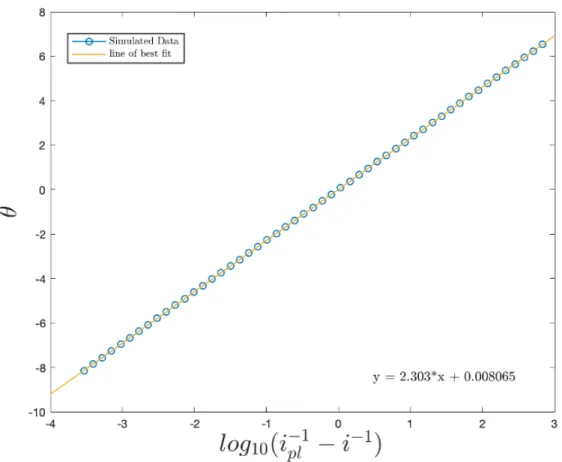
In this chapter, two mathematical models based on the Hale approach and Nernst Diffusion Layer approach were used to approximate the relevant solutions and gen-erate two mathematical models describing the current–potential behavior of the ho-mogeneous ECEC’ mechanism at the RDE.12,35 Digital simulations based on both
models were carried out using a custom MATLAB script that implemented implicit finite difference schemes to approximate each of these models. To test the validity of these models, the current-potential behavior for a reversible electron transfer was calculated. In both cases, mass transport-corrected Tafel plots of 𝜃 vs log(𝑖−1−𝑖−pl1)
(see glossary below for the definition of symbols used) had the requisite slope of2.303,
supporting the use of these numerical approaches.42 The following section focuses on
identify conditions in which the more minimalist Nernst Diffusion Layer approach may be applied. Using these models, methods for extracting kinetic information are developed which have since been experimentally validated.
3.2
Glossary of Symbols
3.2.1
Lowercase Letters
𝑎: dimensionless substrate concentration.
𝑏: dimensionless concentration of the catalytic intermediate B.
𝑐: dimensionless concentration of the catalytic intermediate C.
𝑖𝑝: diffusion-controlled plateau current of catalyst (A).
𝑖𝑝𝑙: plateau current (A).
𝑘𝑏𝑛: backward rate constant for the n
th electron transfer (cm s−1). Butler-Volmer
kinetics stipulate that 𝑘𝑏 =𝑘𝑠𝑒(1−𝛼)𝑓(𝐸−𝐸
∘)
.
𝑘𝑓𝑛: forward rate constant for the n
th electron transfer (cm s−1). Butler-Volmer
kinetics stipulate that 𝑘𝑓 =𝑘𝑠𝑒−𝛼𝑓(𝐸−𝐸
∘)
.
𝑘𝑛: rate constant one for the 𝑛𝑡ℎ chemical step.
𝑘𝑠: standard heterogenous electrochemical rate constant (cm s−1).
𝑝: dimensionless concentration of the catalyst P.
𝑞: dimensionless concentration of the catalytic intermediate Q.
𝑞′: dimensionless concentration of the catalytic intermediate Q′.
𝑟: radial distance from the center of the electrode (cm).
3.2.2
Uppercase Letters
𝐴: oncentration of the substrate in solution (M).
𝐴⋆: bulk concentration of the substrate in solution (M).
𝐵: concentration of the catalytic intermediate following the second E step (M).
𝐿: A constant characteristic of the rotation rate of the disk, and the kinematic viscosity of the solvent used, 𝐿= 0.51023𝜔3/2𝜈−1/2 (cm−1s−1).
𝐷: diffusion coefficient (cm2/s).
𝐸: applied potential (V).
𝐸𝑝/𝑞∘ : standard reduction of the intial E step (V). 𝐸𝑞∘′/𝑏: standard reduction of the second E step (V).
𝑓: F/RT (V−1).
𝐹: Faraday’s constant (C mol−1).
𝑃: concentration of starting catalyst (M).
𝑃⋆: bulk concentration of starting catalyst.
𝑄: concentration of the catalytic intermediate following the first E step (M).
𝑄′: concentration of the catalytic intermediate following the first C step (M).
𝑅: gas constant (J mol−1 K−1).
3.2.3
Greek Letters
𝛼: transfer coefficient.
𝛾: the dimensionless excess factor, 𝛾 = 𝐴𝑃⋆⋆.
𝛿: thickness of the diffusion layer, 𝛿= 1.61𝐷1/3𝜈1/3𝜔1/6 (cm).
𝜃𝑛: dimensionless potential for the nth electron transfer, 𝜃 =−(𝑓)(𝐸−𝐸∘
′
couple).
𝜆𝑛: dimensionless rate parameter for the nth chemical step, 𝜆= (𝛿/𝜇𝑛)
2
(𝑃*).
𝜇: thickness of reaction-diffusion layer, 𝜇= (𝐷𝑐𝑎𝑡/𝑘)1/2 (cm).
𝜈: kinematic viscostiy (cm/s).
𝜏: dimensionless time parameter.
𝜑: azimuthal angle measured from the center of the rotating disk (rad).
Ψ: dimensionless current, Ψ = 𝑖𝑖
𝑝𝑙.
𝜔: Rotation rate of the rotating disc electrode (rad/s).
3.2.4
A Quick Description of the EC Nomenclature
EC Nomenclature
E Electron Transfer C Chemical Reaction
′ Catalytic Turnover
Table 1: Description of the EC Nomenclature
A quick description of the symbols used for the EC Nomenclature is shown above (Table 1). An example of an EC′ reaction mechanism is shown below
E: P + e−←−→Q
C′
Where 𝑘𝑒 is the rate constant of the chemical step in solution.
3.3
Modeling an ECEC
′Mechanism at the RDE:
The Hale and Nernst Diffusion Layer Approach
3.3.1
Theoretical approaches for modeling electrochemical
pro-cesses at the RDE
Theoretical treatment of any convective system requires solutions for a series of rel-evant mass-transport equations.12 Mass transfer of the 𝑖th in solution species to an
electrode is governed by the Nernst-Planck equation which can be written for one-dimensional mass transfer as:
𝐽𝑖(𝑥) =−𝐷𝑖
𝑑𝑐𝑖
𝑑𝑥 −𝑧𝑖𝑓 𝐷𝑖𝑐𝑖 𝑑𝜑(𝑥)
𝑑𝑥 +𝜈(𝑥)𝑐𝑖 (3.1) The three terms on the right-hand side of eqn (3.1) represent the contributions to the mass transfer flux 𝐽𝑖(𝑥) from diffusion, migration, and convection, respectively.
Experimentally, use of sufficiently large electrolyte concentration will suppress mass transport from migration. For sufficiently fast rotation rates, steady-state mass trans-fer results in a time-independent current response because continuous stirring replen-ishes the diffusion layer with fresh material from the bulk solution. These conditions can only be achieved when voltage scans are slow relative to the time required to set up a steady-state concentration profile in the diffusion layer. This is in contrast with stationary voltammetry where the thickness of the diffusion layer increases as a function of time, leading to a time-dependent current response.
For an ECEC′ process at the RDE that does not assume pseudo-first order
the EC′ and ECE mechanisms at steady state (setting the time derivatives to zero),
using homotopic perturbation methods have been recently described.43
Two strategies were employed to simplify and solve these nonlinear reaction-convection-diffusion equations: the Hale approach and the Nernst Diffusion Layer approach. The Hale approach, developed by John Hale, utilizes the traditional con-servation equations that result from the Nernst-Planck equation (3.2) with neglect of the migration term due to the use of supporting electrolyte. The equations that result give rise to a system of nonlinear convection-reaction-diffusion equations with semi-infinite boundary conditions.40Through the use of a elegant transformation and
subsequent rescaling of the spatial domain, Hale was able to reduce the separate con-vection and diffusion terms into a single term, while at the same time compressing the domain, corresponding the entire positive real line, into the unit interval. De-spite Hale’s elegant approach, the resultant system of partial differential equations for a multi-step multi-electron reaction mechanism are still unfortunately impossible to solve analytically.
The Nernst Diffusion Approach, originally employed by Levich, is a simpler one that assumes a steady-state conditions and the existence of a Nernst Diffusion Layer 𝛿 at the electrode’s surface.23 Within the Nernst Diffusion layer, convection is
as-sumed to be nonexistent (even though experimentally this is not the case23) and its
corresponding mathematical term can be neglected. The resulting partial differen-tial equations are then solved within the Nernst Diffusion Layer (0 ≤ 𝑥 ≤ 𝛿) under steady-state conditions giving rise to system of simpler, although typically nonlinear, ordinary differential equations. In addition, under a certain number of limiting condi-tions, the Nernst Diffusion Layer approach, as will be shown below, yields equations analogous to those formulated by Savéant and Costentin for CV for the foot and plateau current of the catalytic RDE voltammogram.41
ap-proaches and compare the results of each under varying reaction conditions. Before we do so, we remark that both the Nernst Diffusion Layer and Hale Transforma-tion MATLAB scripts were originally designed to incorporate a final chemical step corresponding to the ECECC′ mechanism of the cobaloxime catalyst.47 This third
chemical step is included in the MATLAB scripts. In order to negate any effects of this last chemical step on the ECEC’ current-potential curves of interest, the homoge-nous rate constant for the last chemical step was set to equal to a log10 value of 15.
However, any of the rate constants within the simulation scripts can easily be toggled to also incorporate different reaction mechanisms such as EC, ECE, ECEC, ECEC′,
and ECECC′ so long as the homogenous and heterogenous rate constants are chosen
accordingly.
3.3.2
Convection-Reaction-Diffusion Equations for an ECEC’
Mechanism at the RDE
A general ECEC’ mechanism at the RDE is given by the following set of chemical equations:
P + e− ←−→kf1
kb1 Q 𝐸
∘
𝑃 /𝑄
Q + A −−→k1 Q′ Q′+ e− ←−→kf2
kb2 B 𝐸
∘
𝑄′/𝐵
B + A 𝑘2
In the absence of mass transfer by migration, this system can be described by the following non-linear reaction-convection-diffusion equations:
𝜕𝑃 𝜕𝑡 =𝐷
(︂
𝜕2𝑃
𝜕𝑥2
)︂
+𝐿𝑥2
(︂
𝜕𝑃 𝜕𝑥
)︂
+𝑘2𝐵𝐴;
𝜕𝑄 𝜕𝑡 =𝐷
(︂
𝜕2𝑄 𝜕𝑥2
)︂
+𝐿𝑥2
(︂
𝜕𝑄 𝜕𝑥
)︂
−𝑘1𝐴𝑄;
𝜕𝑄′
𝜕𝑡 =𝐷
(︂
𝜕2𝑄′
𝜕𝑥2
)︂
+𝐿𝑥2
(︂
𝜕𝑄′ 𝜕𝑥
)︂
+𝑘1𝐴𝑄;
𝜕𝐵 𝜕𝑡 =𝐷
(︂
𝜕2𝐶
𝜕𝑥2
)︂
+𝐿𝑥2
(︂
𝜕𝐵 𝜕𝑥
)︂
−𝑘2𝐴𝐵;
𝜕𝐴 𝜕𝑡 =𝐷
(︂
𝜕2𝐴 𝜕𝑥2
)︂
+𝐿𝑥2
(︂
𝜕𝐴 𝜕𝑥
)︂
−𝑘1𝐴𝑄 − 𝑘2𝐴𝐵.
Here, 𝐿𝑥2 is given by a truncated series that describes the solution velocity close
to the electrode surface. This is an approximate solution obtained from the Navier-Stokes equation by Von Kármán44 and numerically verified by Cochran45. In this
analysis, we have assumed all chemical species in solution to have identical diffusion coefficients.
One might be curious as to why these equations are posed in only one spatial dimension. The geometry and symmetry of the RDE setup make it convenient to convert the Cartesian coordinates that are commonly used when solving the mass-transfer part of an electrochemical problem to cylindrical coordinates. In cylindrical coordinates, due to symmetry considerations, concentrations are no longer a function of 𝜙 such that 𝜕𝐶𝜕𝜙 = 0 (where C is a generic chemical concentration). In addition,
Levich demonstrated in his seminal work Physicochemical Hydrodynamics that the surface of the RDE is uniformly accessible, which allows us to set 𝜕𝐶
𝜕𝑟 = 0.
23 Thus,
we need only to focus on the coordinate orthogonal to the electrode surface, which in this case is denoted𝑥.
holds.
The boundary conditions in the bulk solution (𝑥 → ∞), as well as the initial
conditions(𝑡= 0), are then given by
𝑃 (𝑥→ ∞, 𝑡 >0) = 𝑃 (𝑥, 𝑡= 0) =𝑃*;
𝑄(𝑥→ ∞, 𝑡 >0) = 𝑄(𝑥, 𝑡= 0) = 0;
𝑄′(𝑥→ ∞, 𝑡 >0) = 𝑄′(𝑥, 𝑡= 0) = 0;
𝐵(𝑥→ ∞, 𝑡 >0) = 𝐵(𝑥, 𝑡= 0) = 0;
𝐴(𝑥→ ∞, 𝑡 >0) = 𝐴(𝑥, 𝑡= 0) =𝐴*.
The boundary conditions at the RDE surface (𝑥= 0) are given by:
(𝜕𝑃
𝜕𝑥)𝑥=0 =𝑘𝑓1𝑃(𝑥= 0)−𝑘𝑏1𝑄(𝑥= 0) ;
(𝜕𝑄
′
𝜕𝑥 )𝑥=0 =𝑘𝑓2𝑄
′
(𝑥= 0)−𝑘𝑏2𝐵(𝑥= 0) ;
(𝜕𝑄
𝜕𝑥)𝑥=0 = −( 𝜕𝑃
𝜕𝑥)𝑥=0;
(𝜕𝑄
′
𝜕𝑥 )𝑥=0 = −( 𝜕𝐵
𝜕𝑥)𝑥=0;
(𝜕𝐴
𝜕𝑥)𝑥=0 = 0.
where the forward and backward electron transfer rate constants are defined in terms of the standard Butler Volmer kinetics treatment.12
3.3.3
Derivation of the Hale Approach
Now that we have the appropriate initial and boundary conditions, we begin with our derivation of the Hale approach. First, the system of equations are cast into dimensionless forms by introducing the following set of variables:
𝑊 = (𝐿
𝐷)
1
3𝑥; 𝜏 =(︀𝐿2𝐷)︀ 1
3 𝑡; 𝜆
1 =𝑘1𝑃*𝐿− 2 3𝐷−
1
3; 𝜆2 = 𝑘2𝑃*𝐿− 2 3𝐷−
![Figure 1 : TD-DFT calculated absorption spectra for the first 12 excited states of the trans-[CpW(CO) 3 ] 2 dimer](https://thumb-us.123doks.com/thumbv2/123dok_us/8240149.2183935/15.918.212.676.114.469/figure-calculated-absorption-spectra-excited-states-trans-dimer.webp)
![Figure 3 : (Bottom) 1 H NMR spectra of the [CpW(CO) 3 ] 2 dimer in a solution of deuterated acetonitrile before photolysis was performed](https://thumb-us.123doks.com/thumbv2/123dok_us/8240149.2183935/18.918.219.701.185.497/figure-spectra-dimer-solution-deuterated-acetonitrile-photolysis-performed.webp)
![Figure 4 : Displacement ellipsoid (50% probability) plot for the structure [CpW(CO) 3 NCCH 3 ] + [PF 6 ] −](https://thumb-us.123doks.com/thumbv2/123dok_us/8240149.2183935/19.918.344.597.762.953/figure-displacement-ellipsoid-probability-plot-structure-cpw-ncch.webp)
![Figure 5 : (Left) Concentration profiles of the [CpW(CO) 3 ] 2 (red) and CpW(CO) 3 H (blue) for the reaction of the [CpW(CO) 3 ] 2 with [PyH][BF 4 ] under continuous photol-ysis conditions with an 455nm LED lamp](https://thumb-us.123doks.com/thumbv2/123dok_us/8240149.2183935/20.918.155.779.457.671/figure-left-concentration-profiles-reaction-continuous-photol-conditions.webp)
![Figure 6 : (Left) Initial concentration profiles of CpW(CO) 3 H (WH) formed from the photochemical disproportionation of [CpW(CO) 3 ] 2 in the presence of three differ-ent pyridinium tetrafluoroborate acid concdiffer-entrations (PyH) are plotted and fit t](https://thumb-us.123doks.com/thumbv2/123dok_us/8240149.2183935/21.918.134.803.477.730/concentration-photochemical-disproportionation-presence-pyridinium-tetrafluoroborate-concdiffer-entrations.webp)