Proceedings of the
11th International Workshop on Graph Transformation and
Visual Modeling Techniques
(GTVMT 2012)
Remedy of Mixed Initiative Conflicts
in Model-based System Engineering
Fenglin Han and Peter Herrmann
14 pages
Guest Editors: Andrew Fish, Leen Lambers
Managing Editors: Tiziana Margaria, Julia Padberg, Gabriele Taentzer
Remedy of Mixed Initiative Conflicts
in Model-based System Engineering
Fenglin Han1and Peter Herrmann2
http://item.ntnu.no/
Department of Telematics
Norwegian University of Science and Technology, Trondheim, Norway
Abstract: SPACE is a technique for model-driven engineering of reactive
dis-tributed systems. One of the strengths of its tool-set Arctis is that the system en-gineer can formally analyze the models for design errors such that these can be corrected early in the development process. In this paper, we go a step further and introduce a technique that refines the fault detection and, in addition, offers a highly automatic mechanism to remedy the errors. For that, we combine model checking, the already existing analysis method of Arctis, with graph transformation. Using graph rewriting rules, we can analyze the state space graph of a system for the exact reason of an error as well as remove the erroneous parts of a model by changing the model description. We exemplify the approach by envisaging the detection and rem-edy of mixed initiatives, a quite common cause for faulty behavior in event-driven systems that often is overlooked in system development.
Keywords:graph transformation, model driven engineering, mixed initiative.
1
Introduction
New application domains like sensor networks, smart grids, and machine to machine cooper-ation call for novel networked services and appliccooper-ations. To engineer these often reactive and embedded distributed systems, we provide the development method SPACE and its tool-set Arc-tis [KSH09, KH09]. System behavior is modeled by UML activities [Obj10] that use a token semantics close to Petri nets. The activities have been provided with a new reactive formal semantics [KH10] that enables to analyze the models formally [KSH09] and to create code au-tomatically [KH07]. The technique is scalable since we can enclose partial behavior into UML call behavior actions that we call blocks. On the one hand, a block embraces an activity and, on the other, it can be used as an element in another one. So, it links both activities together. The static role-binding of the blocks is modeled by UML collaborations while we use External State Machines (ESMs, [KH09]) to define the interface behavior of a block. Furthermore, the block structure enables a high degree of reuse of system models which is in average 70% in our models [KH09].
can be executed in a non-interactive way and the traces towards detected errors are animated on the UML activities, the Arctis user does not need a deeper understanding of the formalism used. The state explosion problem of model checking is mitigated by compositional verification since the ESMs allow to prove every activity in the system model separately [KSH09].
Up to now, the Arctis analysis has not supported automatic remedy of detected errors which has to be provided manually by the system engineer. This paper describes a solution to support the Arctis user further. In particular, we introduce a way to analyze the state graph of an erro-neous model and to correct the specification with a high degree of automation. For that, we ap-ply graph transformation that already proved helpful for the model transformation of flow-global choreographies, a more abstract way to specify reactive systems, to Arctis models [HKL+11]. Graph transformation is suitable since UML activities, collaborations and state machines all are graphical description techniques which can be directly accessed by graph rewriting rules.
For the error detection, we align graph transformation with model checking in Arctis. In particular, we analyze the state space of an activity generated by the model checker to find out if the detected errors belong to a particular class. Thereafter, we use rules to correct the erroneous part of the activity. We illustrate our approach with a mechanism for the detection and remedy of mixed initiatives between two parties.
2
Mixed Initiatives
Mixed initiatives [GY84, BH93, SDW08] are a special form of race conditions that is often overseen when developing reactive distributed systems. A mixed initiative conflict may occur whenever two (or more) distributed components can trigger an interaction with each other at the same time (see [Flo03]). Due to the asynchronous communication between the two parties, both can start own initiatives before being notified that also the partner triggered one. Of course, this behavior can be mitigated but that often demands for a complex new functionality. While mixed initiatives in practice are often overlooked, the Arctis model checker detects that a system contains faulty behavior (see [KSH07]). By the methods introduced in this paper, we can find out if a mixed initiative is indeed the reason of an error. Further, we introduce a graph-based approach to correct mixed initiatives between two entities. The only condition for the remedy mechanism is that the system behavior contains an interaction between the entities before the mixed initiative can take place.
2.1 Arctis
/remoteWins2 /remoteWins1
start/
Button Game
start
remoteWins1 remoteWins2
b2:Button b1:Button
stop stop
pushed
pushed component1 component2
M1
M2
M3
localWins1
/localWins1
(a) (b)
s0
s1
Figure 1: Arctis building blockButton Gameand its ESM
A UML activity [Obj10] is a directed graph and, due to the token flow semantics, behavior is modeled as tokens walking across the nodes of the graph following its edges. The edges may either stay within a partition, specifying local behavior of the corresponding component, or cross the partition borders (e.g.,M1,M2,M3). In the latter case, they model asynchronous interaction
between two components. Activities offer a set of general node types enabling to start, stop, or interrupt token flows as well as nodes for routing and handling parallel flows respective for the execution of certain operations. An example are forks of which four copies are used in Figure1
(a). They are expressed by bold bars in right angle to the linked edges. A fork contains one incoming edge and at least two outgoing edges and models that an incoming token is duplicated and a copy is sent via each of the downstream edges. Thus, forks enable to specify parallel flows. Another node type used in the activity Button Gameare call behavior actions describing the Arctis building blocks. A block represents an own activity that is linked with the one including it by means of pins1 which are depicted as small rectangles on the edge of a block respective
an activity and filled with in- or outgoing arrows. The interface behavior of a block is specified by External State Machines (ESM, [KH09]) that are simple UML state machines describing in which order flows may pass the various pins.
Figure1(a) includes the two blocksb1andb2of the typeButtonwhich are taken from an Arc-tis library for Android devices (see [Kra11]). This block type describes the logic when pushing a certain button of an Android device which initially is inactive. The button is armed by sending a token flow through its pinstarton the top of the block. Thereafter, pushing the button leads to a flow via the pinpushedwhich, in addition, terminates and disarms the block. Further, the block can be disarmed from its environment by a token passing pinstop, too.
The Arctis semantics [KH10] defines so-called activity steps describing the sub-graph passed by a token in an atomic transition. In short, a token may rest only on nodes or edges describing places where it has to wait for a stimulus. An example are the crossing edges. To model the asynchronous communications between the partitions, a token passing a crossing edge has to wait on it until it is passed on in a new activity step. After being triggered by an internal or
(1) (2)
M1
M2
(3) (4) (5) (6)
M1
M2 M3 M3
Figure 2: Activity steps ofButton Game
external event, e.g., the reception of the transmitted data, tokens pass all nodes and edges of the activity step in run-to-completion fashion until they reach nodes and edges on which they have to wait for new triggers.
Figure2 shows the six activity steps of the UML activity in Figure1 (a). Activity step (1) describes the start of the game. It is triggered by a token passing the parameter nodestartat the edge of the blockButton Gamewhich is duplicated at the fork node and copies are sent to both blockb1and to the crossing edgeM1. Activity step (2) forwards the token to blockb2such that
both buttons are armed. Pushing a button leads to the activity steps (3) and (4) respective (5) and (6) which disarm the other button and notify the environment of the button game about the winner via the parameter nodeslocalWinsandremoteWins.2
Figure 1(b) shows the External State Machine (ESM, [KH09]) of the blockButton Game. The block is started by a token passing pin start. Thereafter, it terminates either by a token arriving atremoteWins1or by one at localWins1followed by another one at remoteWins2. In the transition markings, the “/” behind a pin designator refers to tokens heading towards the block while positioning “/” in front refers to tokens coming from the block and going towards its environment.
2.2 A Mixed Initiative Error
It is easy to see that the system renders unexpected behavior if both buttons are pushed at the same time. Then due to the asynchronous communication between the components, the buttons will be terminated too late and tokens leave the pinspushedof both blockb1andb2. In conse-quence, all the activity steps (3) to (6) are executed and the ESM in Figure1(b) is violated as all
localWins1,remoteWins1andremoteWins2are fired. This will be detected by the Arctis analyzer
using model checking. Figure3(a) depicts the state space generated by the Arctis analyzer. To facilitate the understanding of the state graph, we added the identifiers of the edges crossing the partition borders. One can see that the traces towards the states 8 and 9 contain a sequence of pins violating the ESM.
2For simplicity, we only notifycomponent 1, that takes the role of the game manager, fully about the result while
idle s0 s1 s3 s4 s2 s6 s5 pWi start/ secI/ /started /secA primI/ /started secI/ primI/ secI/ /primA sWi /secAc /secOv
(a) State Space of Button Game Building block before
weaving
(b) State Space of the Button Game after adding
block Mixed Initiative 2
0 1 2
3 4
5
6 7 8
9 10
11
12
M1! M3!
M1?
M3?
M2! M1?
M3!
M2!
M3?
M2?
M2?
M3? M3!
M2?
Normal state
Conflict state
States showing errors by Arctis checker
Mixed-initiative state
Figure 3: State spaces of the original and the modified blockButton Game
3
Mixed Initiative Detection
To identify that a mixed initiative is the actual cause for property violations detected by the Arctis model checker, we investigate the state space further using graph rewriting. According to Floch [Flo03], a mixed initiative is indicated by so-calledmixed initiative statesin which a component may both send and consume signals. The danger of a mixed initiative exists if two interacting components are both in a mixed initiative state at the same time.
In a first step, we label the edges with send and receive labels using the technique explained
in [Kra09]. In our example that areM1,M2andM3referring to the three partition crossing edges
in the activity depicted in Figure1(a). By the “!” we describe the sending and by “?” the recep-tion of a communicarecep-tion between the two components. SinceM1andM3show communication
fromcomponent 1tocomponent 2andM2the other way around, one can see that the states 3 and
11 of the state graph refer to mixed initiative states according to the definition of Floch. In state
3,component 2may both sendM2and receiveM3 while in state 11component 1may sendM3
and receiveM2. By executing the corresponding send actions, both mixed initiative states lead to
state 6 which expresses that the two signals forwarding the conflicting initiatives just pass each other. We call it aconflict state.
Thereafter, we can check if the traces from the initial node towards the states violating a property always lead via a conflict state. To avoid false positives, we only assume a mixed initiative as the source of errors if all traces to all error states pass at least one conflict state. In our example, the violation of the ESM is detected when reaching the states 8 or 9 and it is easy to see that all traces from the initial state 0 to them pass the conflict state 6.
Technically, we export the state graph created by the Arctis model checker and label the states using the graph transformation tool AGG [Tae04] according to the following rules:
1. Initially, the subgraph contains the error states of the state graph.
2. For any vertex in the subgraph that is not a conflict state, we add all its incoming edges as well as their source states to the subgraph.
mi:Mixed Initiative 2 start
secA started
secI
secOv primA
primI
secAc
(a) (b)
start/ secI/
/started secI/
secI/ primI/
/started
primI/ /secA
/secOv /secAc
/primA
Figure 4: The Arctis blockMixed Initiative 2
Thus, if the initial node is not in the resulting subgraph, we know that all traces from it to the error states pass a conflict state which gives us advice that an improperly handled mixed initiative might be the source of the errors. For example, in Figure3(a) the subgraph consists of the states 6 to 9 and the edges linking them but not the initial state 0 showing that the mixed initiative between the crossing edgesM2andM3are the likely reason for the problem.
The AGG rules use the state space generated by the Arctis model checker as input and are executed automatically without further human intervention. Thus, it is also possible to integrate the algorithm into the Arctis model checker which would enable a seamless detection of mixed initiatives already during the analysis. The integration is planned for one of the next revisions of the model checker.
4
Mixed Initiative Remedy
An established way to deal with errors caused by mixed initiatives is to use prioritization [GY84]. Here, the two conflicting initiatives are marked asprimaryrespectivesecondaryand, in the case of a conflict, only the primary initiative will take place while the secondary is stopped during communication. In our example, we decided that the initiativeM2leavingcomponent 2shall be
the primary one, such that it will always be forwarded tocomponent 1whileM3will be stopped in the case of a conflict. Of course, this prioritization scheme demands a somehow complex logic which, however, can be hidden in a reusable Arctis block as we point out in the following.
4.1 Arctis Blocks handling Mixed Initiatives
Since mixed initiatives are a recurrent phenomenon in reactive distributed software, we created two building blocks providing remedy by prioritization (see [KSH07]) which are available in one of the Arctis libraries. Figure4(a) shows one of them. It supports two participantsprimaryand
secondaryand arranges that an initiative from the primary one is prioritized against the one of
the secondary.
<<System>>
Secondary Primary
Source St
Target Ip
Target Is Target St
Source Ip
Source Is St
Ip
Is
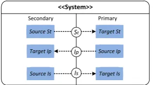
Figure 5: Pattern of a system to be adapted with building blockMixed Initiative 2
participant to send its secondary initiative via pin secI. Eventually, the start is notified via pin
startedto the primary party who is afterwards enabled to start an own initiative via pinprimIas
long as no secondary initiative passes pinsecA. If the secondary initiative arrives without being interfered by the primary one, the secondary participant is notified about that via a flow leaving the block through pinsecAc. If only a primary initiative takes place, the secondary receives it via pinprimA. If both participants send parallel initiatives viaprimIandsecI, the secondary is never delivered while the primary one is handed over to the secondary participant via pinsecOv
notifying it that the own one was overridden. The other block in the Arctis library is similar but started from the side of the primary component.
4.2 Adding the Arctis Blocks
It is demanded that the two Arctis blocks introduced above, have to be started using the pinsstart
andstarted before they may handle a mixed initiative. Thus, the system needs a crossing edge
between the two partitions that may be redirected in order to act as a starter. To find such an edge, we first analyze the subgraph derived by the algorithm in Sect.3and check if there is a crossing edge on all traces towards the mixed initiative that can take that role. Thus, in integrating a mixed initiative block, we have to consider three crossing edges as depicted in the pattern description in Fig.5. This pattern for the Arctis blockMixed Initiative 2(and except of the partition designators also of the other available block) consists of a crossing edge calledStdescribing the starter while
IsandIprefer to the crossing edges which may cause the mixed initiative error.
In order to allow an adaptation according to the needs of the system engineer, the transfor-mation process is started by asking the engineer for two decisions depending on which a certain group of AGG graph rewrite rules is selected:
1. The engineer has to determine which component should take the role of the primary party in order to identify which of the two mixed initiative blocks needs to be built in.
2. A principle decision about the strategy to handle detected mixed initiatives has to be taken. This reflects, that the two blocks make the occurrence of a mixed initiative visible to the secondary participant and additional functionality handling this case has to be added. Here, we see two different strategies:
when the behavior to be performed by a component is the same irrespective of which party triggered the initiative. In this case, we only have to prevent that this behavior is carried out twice.
(b) Let the primary initiative prevail and neglect the impact of the secondary one. This solution is useful if both initiatives lead to a different behavior of the involved com-ponents.
According to the two decisions, a particular set of AGG graph rewrite rules is selected which execute the integration of a mixed initiative block automatically. If we decide for the strategy to let the primary initiative prevail, however, we face the problem that we need additional func-tionality to neglect the secondary initiative in case of a conflict. This, however, depends on the particular model, and it is beyond the capabilities of a graph transformation system to decide if any operation executed before passing Is should also be executed in case of a conflict. To elude this problem, we selected a graph transformation mechanism that renders a correct solu-tion for most funcsolu-tionalities. Nevertheless, it demands that the system engineer looks on the system model resulting from the graph transformation since it is possible that some of the op-erations have to be rearranged on the local side of the secondary participant. Thus, the graph transformation does not create the correct solution automatically in all cases but we think that it is nevertheless helpful since it reduces a possible manual post-processing to the purely local reordering of single operations which is much easier than the integration of a complex distributed solution from scratch.
At first, the crossing edges correspondingSt,IsandIpin the pattern model are removed and the Arctis mixed initiative blockmiis added to the model. The remainder of the graph transformation is the connection of the sources respective targets of the removed edges with the pins ofmiby new edges. For brevity, we describe this process only for the blockMixed Initiative 2listed in Fig.4as this procedure is similar for the other block. At firstSource St, i.e., the source node of edgeSt, will be linked with the pinstartofmiwhile pinstartedis connected toTarget St.
On the primary partition, the new wiring of the two conflicting edgesIpandIsis straightfor-ward since the mixed initiative block disburdens the primary component from any error correc-tion handling.Source Ipis coupled with the pinprimIand pinsecAwithTarget Is.
The wiring of the secondary component, however, differs depending on the treatment strategy selected. If both conflicting signals shall be deleted,Source Isis connected with pinsecIand pin
PrimAwithTarget Ip. The pinsSecOvandSecAc are not linked at all which according to the
robust Arctis semantics means that tokens passing them are deleted.
For the strategy to let the primary initiative prevail, the particular wiring affords to link the pin
primAwithTarget Ipsince this pin reflects that there was no conflict at all. A token passing pin
secOvcontains the data of the primary initiative in the case of a mixed initiative conflict. Since
this initiative should prevail, there has also to be made a connection from this pin toTarget Ip. Actually, the graph transformation rules link both pins primAandsecOvwith a newly created merge, i.e., an activity node with at least two ingoing edges but only one outgoing edge to which all incoming tokens are routed. The merge is further connected downstream withTarget Ip.
exe-remoteWins2
Button Game
start
remoteWins1 localWins1 b1:Button
stop pushed
b2:Button
stop pushed mi:Mixed Initiative
Secondary Starter
start
secA started
secI
secOv
primA primI
secAc
Figure 6: The building blockButton Gameafter the transformation
cuted when a token passes. For instance, an operation towards a crossing edge may prepare the transfer format readable by the primary component. After the model modification, such oper-ations shall still be on the path leading to the pinsecI. Other actions, however, shall only take effect if a conflict does not occur3such that they should be linked to the pinsecAc.
While, as already stated, a general solution to decide about where to place the operations resting on the secondary component before the crossing edgeIsis not possible, we can automate the case thatSource Isis a fork node. Here, it is evident that all downstream edges of the fork except for the crossing edge are not relevant for a correct transmission of the secondary initiative. Thus, we can propose a wiring as follows:
1. IfSource Isis not a fork, it will be connected with pinsecIand pinsecAcwill not be linked at all.
2. IfSource Isis a fork with two outgoing edges in total, it will be deleted. The source node of its incoming edge will be linked with pinsecIand pinsecAcwill be connected with the target node of the outgoing edge that is not the crossing edge.
3. If the source node is a fork with three or more outgoing edges, the source node of its incoming edge will also be linked with the pinsecI. Moreover, we connect the pinsecAc
to the fork such that it is only passed in the case of a successful secondary initiative.
For our button game example, we selectedcomponent 1as the secondary andcomponent 2as the primary partition. Further, we decided to let the primary initiative prevail since, otherwise the pinremoteWins1would not be executed in the case of conflict which would violate the ESM of blockButton Game(see Fig.1). The result of the graph transformation is depicted in Fig.6. The modified model produces the state space shown in Fig. 3 (b) such that the ESM of the surrounding blockButton Gameis obeyed. One should mention that the analyzer issues no error
Figure 7: Rule inserting the blockMixed Initiative 2
but a warning since in the case of a mixed initiative a flow leads to the pinstopof blockb1which is already terminated. This flaw is of no practical relevance as Arctis simply removes tokens in this case what is exactly what we want. So, we do not need any manual re-orderings.
5
Graph Transformation Rules
In this section, we briefly introduce the concept of graph rewriting rules used for the various mixed initiative detection and remedy steps discussed above. As tool-set for the graph transfor-mation we use the Attributed Graph Grammar System4 (AGG) [Tae04] that, in a flexible way, allows the visually supported creation of rules. Since AGG offers Java APIs, it could be easily integrated into Arctis that is also Java-based.
The transformation rules mainly consist of two parts. A pre-pattern describes a graph pattern that has to be replaced while the corresponding post-pattern models the result of the replacement. Moreover, a rule may contain additional conditions to constrain when it may be applied. The input to a rule is a so-called host-graph which, by replacing the part matching the pre-pattern by the post-pattern, will be transformed to a post-graph.
Altogether 22 rules are used to detect mixed initiatives and to add one of the two Arctis mixed initiative blocks to a UML activity-based system model. For the sake of brevity, we list only the different categories of rules and provide a closer description of only one rule while the others can be looked at on the WWW.5The rules can be structured in three groups:
1. Label the states of an Arctis state graph to detect a mixed initiative as discussed in Sect.3.
2. Search for the pattern described in Fig.5of the state graph to create a subgraph with labels. During this stage the crossing edgesIp,IsandSt are marked.
3. Insert the selected Arctis mixed initiative block and wire it with its environment as de-scribed in Sect.4.2.
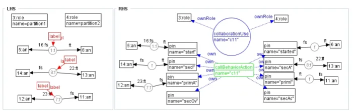
Figure7shows a rule of group 3 that is used to add the blockMixed Initiative 2to an activity. On the left side, the pre-pattern is depicted. It contains the classes 3 and 4 of typerolewhich refer
4We currently replace AGG by Henshin [ABJ+10] which is more flexible and supports the Eclipse Modeling
Frame-work (EMF) also used by Arctis.
to the two partitions of the activity. These two constructs are applied to enhance the collaboration description used in Arctis to model the relation between blocks and particular components. The other constructs refer to the activities to be amended. In particular, the three labeled cycles refer to the crossing edges involved while label 1:f describes the one to be used to start the block. Label 7:f refers to the primary and 8:f to the secondary initiative. The post-pattern is shown on the right side. The collaboration is extended by a new collaboration use that corresponds to the added mixed initiative block as well as to the links to the two components. The activity is supplemented by a call behavior action, i.e., an Arctis block, as well as references to its pins. The various edges of the pre-pattern are now replaced by others linking the original source respective target nodes with the appropriate pins of the mixed initiative blocks. This rule is used for both strategies mentioned in Sect. 4.2. It renders the final result if we want to delete both mixed initiatives. If we like to let the primary initiative prevail and neglect the secondary one, it creates an intermediate system model which will be further amended by other rules.
6
Related work
In visual language-based specification techniques like the UML, graph grammar techniques are more and more utilized. For instance, in [WTEK08] Winkelmann et al. translate restricted OCL constraints into equivalent graph constraints which enables an automatic generation of instance models from the OCL meta-models. Gronmo and Møller-Pedersen propose so-called aspect activity diagrams that extend activity models by aspect-oriented weaving [GM08]. Likewise, Mussbacher et al. use an extension of the User Requirement Notation (URN) to weave in as-pects [MWA10]. A difference to our approach is that both techniques demand for explicit syntax extensions to define aspect orientation concepts like point cuts, which makes the understanding of the models more complicated. In [HHR+11], Heged¨us et al. use graph grammars as the fun-damental technique of the framework to generate quick fixes of business flows specified in the Business Process Model and Notation (BPMN). Like our work, this approach uses graph trans-formation for the remedy of errors, albeit on a more abstract modeling level. Our work is also similar with [LK10] who use graph transformation rules to slice UML models using transforma-tion rules. The difference is that Lano and Kolahdouz-Rahimi concentrate on the slicing of state machines.
7
Concluding Remarks
We introduced the use of graph transformation for the detection and remedy of mixed initiative conflicts, a particular kind of development errors in distributed systems. The approach is highly automatic and promises to support the engineer significantly in error recovery and remedy. The set of rules was also applied to a wake-up call scenario [KSH07] as it is used in hotels. Again we received a correct result that did not need further manual corrections.
To generalize this experience, we have also to guarantee that the model transformation does not introduce new errors. In particular, we must assure that the new wiring complies with the proper-ties of the integrated mixed initiative block. Further, we have to prove that the transformed model is consistent with the original one. Of course, as desired, the model transformation changes the system behavior to solve the conflict but it should not be changed in the ordinary case that only one initiative takes place at a time. These two questions can be verified in temporal logic which, however, cannot be shown here due to the space limit.
There are other system layouts which might lead to mixed initiatives, e.g., three or more components may use ring-shaped communication such that there are no conflicting crossing edges between any two of them. We want to find out more system patterns that indicate mixed initiatives and create corresponding graph transformation rules to alleviate them. Further, we intend to use the approach for the detection and remedy of other kinds of errors.
Graph transformation seems also promising to add security protection against malicious at-tacks. While the integration of counter-measures, in general, is complex and tedious, in some cases it can be done with limited human guidance such that graph transformation is the ap-propriate means. An example is [GKH11] introducing the structured integration of security mechanisms to protect sensible communications against wiretapping.
The work introduced above was the second approach utilizing graph transformation in SPACE. Before, we used this technique to transform flow-global choreographies, a more abstract model-ing technique, to Arctis models [HKL+11]. Both approaches profit from the fact that it is much easier to create and change a set of graph rewrite rules than to develop a model transformation tool doing the same model changes manually. This allows for an easy adaptation of engineering tools for visual languages to new challenges arising during deployment.
A strength of Arctis is that it supports reuse of sub-models in certain application domains. In average, 70% of a system model consist of building blocks reused from previous projects (see [KH09]). Utilizing the flexibility of graph rewriting, one can complement the domain-specific libraries of Arctis blocks with sets of graph transformation rules such that an engineer is not only provided with suitable sub-models but also with a convenient functionality to deal with them.
Acknowledgments The research was carried out under the research and development project
“Infrastructure for Integrated Service” (ISIS) funded by the Research Council of Norway.
Bibliography
Proceedings of the 13th Int. Conference on Model Driven Engineering, Languages
and Systems (Models). LNCS 6394, pp. 121–135. Oslo, 2010.
[BH93] R. Bræk, Ø. Haugen. Engineering Real Time Systems — An Object Oriented
Methodology using SDL. Prentice Hall, 1993.
[BPVR09] A. Bucchiarone, P. Pelliccione, C. Vattani, O. Runge. Self-Repairing systems mod-eling and verification using. InSoftware Architecture, 2009 European Conference on Software Architecture. WICSA/ECSA 2009. Joint Working IEEE/IFIP Conference on. Pp. 181–190. 2009.
[Flo03] J. Floch.Towards Plug-and-Play Services: Design and Validation using Roles. PhD thesis, Department of Telematics, Norwegian University of Science and Technology (NTNU), 2003.
[GKH11] L. Gunawan, F. A. Kraemer, P. Herrmann. A Tool-Supported Method for the De-sign and Implementation of Secure Distributed Applications. InEngineering Secure
Software and Systems. LNCS 6542, pp. 142–155. Springer, 2011.
[GM08] R. Grønmo, B. Møller-Pedersen. Aspect Diagrams for UML Activity Models. In Sch¨urr et al. (eds.), Applications of Graph Transformations with Industrial
Rele-vance. Pp. 329–344. Springer-Verlag, Berlin, Heidelberg, 2008.
[GY84] M. G. Gouda, Y.-T. Yu. Synthesis of Communicating Finite State Machines with Guaranteed Progress.IEEE Transactions on Communications32(7), July 1984.
[HHR+11] ´A. Heged¨us, ´A. Horv´ath, I. R´ath, M. Branco, D. Varr´o. Quick fix generation for DSMLs. InIEEE Symposium on Visual Languages and Human-Centric Computing
(VL/HCC). IEEE Computer, Pittsburgh, PA, USA, 2011.
[HKL+11] F. Han, S. B. Kathayat, H. N. Le, R. Bræk, P. Herrmann. Towards Choreography Model Transformation via Graph Transformation. InIEEE Conference on Software
Engineering and Service Science, ICSESS 2011. IEEE Computer, Beijing, 2011.
[JPW02] J. J¨urjens, G. Popp, G. Wimmel. Towards Using Security Patterns in Model-based System Development. 2002.
[JWEG07] P. K. Jayaraman, J. Whittle, A. M. Elkhodary, H. Gomaa. Model Composition in Product Lines and Feature Interaction Detection Using Critical Pair Analysis. In Engels et al. (eds.),MoDELS. LNCS 4735, pp. 151–165. Springer, 2007.
[KH07] F. A. Kraemer, P. Herrmann. Transforming Collaborative Service Specifications into Efficiently Executable State Machines.ECEASST6, 2007.
[KH09] F. A. Kraemer, P. Herrmann. Automated Encapsulation of UML Activities for In-cremental Development and Verification. In Sch¨urr and Selic (eds.),Proceedings of the 12th Int. Conference on Model Driven Engineering, Languages and Systems
(Models), Denver, Colorado, USA, October 4-9, 2009. LNCS 5795, pp. 571–585.
[KH10] F. A. Kraemer, P. Herrmann. Formal Techniques for Distributed Systems, Joint 12th IFIP WG 6.1 International Conference, FMOODS 2010 and 30th IFIP WG 6.1 Inter-national Conference, FORTE 2010, Amsterdam, The Netherlands, June 7-9, 2010. Proceedings. In Hatcliff and Zucca (eds.),Formal Techniques for Distributed Sys-tems. LNCS 6117. Springer, 2010.
[Kra09] F. A. Kraemer. Automatic Generation of Compatible Interfaces from Partitioned UML Activities. In Reed et al. (eds.), SDL 2009: Design for Motes and Mobiles. LNCS 5719, pp. 182–199. Springer Berlin / Heidelberg, 2009.
[Kra11] F. A. Kraemer. Engineering Android Applications Based on UML Activities. In Whittle et al. (eds.), Model Driven Engineering Languages and Systems. LNCS 6981, pp. 183–197. Springer Berlin / Heidelberg, 2011.
[KSH07] F. A. Kraemer, V. Sl˚atten, P. Herrmann. Engineering Support for UML Activities by Automated Model-Checking — An Example. In4th International Workshop on
Rapid Integration of Software Engineering Techniques (RISE). 2007.
[KSH09] F. A. Kraemer, V. Sl˚atten, P. Herrmann. Tool Support for the Rapid Composition, Analysis and Implementation of Reactive Services.Journal of Systems and Software
82(12):2068–2080, 2009.
[LK10] K. Lano, S. Kolahdouz-Rahimi. Slicing of UML Models Using Model Transfor-mations. In Petriu et al. (eds.),Model Driven Engineering Languages and Systems. LNCS 6395, pp. 228–242. Springer Berlin / Heidelberg, 2010.
[MVDJ05] T. Mens, N. Van Eetvelde, S. Demeyer, D. Janssens. Formalizing refactorings with graph transformations: Research Articles.J. Softw. Maint. Evol.17:247–276, 2005.
[MWA10] G. Mussbacher, J. Whittle, D. Amyot. Modeling and detecting semantic-based inter-actions in aspect-oriented scenarios.Requirements Engineering15:197–214, 2010.
[Obj10] Object Management Group. Unified Modeling Language: Superstructure, Version 2.3. 2010.
[SDW08] C. Shin, A. K. Dey, W. Woo. Mixed-initiative conflict resolution for context-aware applications. InUbiComp’08. Pp. 262–271. 2008.
[Tae04] G. Taentzer. AGG: A Graph Transformation Environment for Modeling and Valida-tion of Software. In Pfaltz et al. (eds.),Applications of Graph Transformations with
Industrial Relevance. LNCS 3062, pp. 446–453. Springer, 2004.