April 2016
Contents
Sheet 3022
23
24
25
26
27
28
29
30
31
32
33
34
35
36
37
38
39
40
41
42
43
001Mot
or Star
te
rs and
Contact
ors—Lo
w V
oltag
e
Motor Starters and Contactors—Low VoltageManual Motor Control
MS Starter with Hand/Auto . . . 30.1-1
MS Manual Motor Starters . . . 30.1-2
Type B100 . . . 30.1-3 XT Manual Motor Protectors . . . 30.1-4 Lighting Contactors
Non-Combination Lighting Contactors . . . 30.2-1
Electrically Held Non-Combination—CN35 . . . 30.2-2
Mechanically Held Non-Combination—C30CNM . . . 30.2-5
Magnetically Latched—202 . . . 30.2-9
Enclosed Combination Type—ECL . . . 30.2-11 NEMA Motor Starters—Electromechanical
NEMA Motor Starters Freedom Series. . . 30.3-1
C440 Series . . . 30.3-11
C441 Motor Insight Motor Protection Relays . . . 30.3-13
C440/XT Electronic Overload Relay . . . 30.3-15 XT IEC Power Control . . . 30.3-20
EMS Electronic Motor Starter . . . 30.3-34 Reduced Voltage—Electromechanical General Description . . . 30.4-1 Autotransformer. . . 30.4-2 Part Winding . . . 30.4-3 Wye-Delta . . . 30.4-4 Reduced Voltage—Solid-State General Description . . . 30.5-1
S801 Solid-State Reduced Voltage Soft Starter . . . 30.5-6
S811 Solid-State Reduced Voltage Soft Starter . . . 30.5-10
S611 Solid-State Reduced Voltage Soft Starter . . . 30.5-18
DS6 Soft Start Controllers . . . 30.5-26
DS7 Soft Start Controllers . . . 30.5-35
PSG Series DC Power Supplies. . . 30.5-44 Enclosures
General Information. . . 30.6-1
Enclosure Dimensions . . . 30.6-3 Group Control—Multi-Pak . . . 30.7-1 Specifications:
See Eaton’s Product Specification Guide, available on CD or on the Web. CSI Format: . . . 1995 2010
Sections 16481, Sections 26 29 13.11,
16484, 26 29 13.13,
16485, 26 29 13.15,
16902 26 29 05
Enclosed S801 Soft Start and Freedom NEMA Starter with C440 Electronic Overload Relay
April 2016 Sheet 30
22
23
24
25
26
27
28
29
30
31
32
33
34
35
36
37
38
39
40
41
42
43
002April 2016 Sheet 30
22
23
24
25
26
27
28
29
30
31
32
33
34
35
36
37
38
39
40
41
42
43
Manual Motor Control
Type MS 003
MS Starters with Hand /Auto
Maximum 1 hp, 120/277 Volts
Single-Phase
General Purpose Type 1 Enclosed MS Starter with Hand/Auto and Pilot Light
General Description
The enclosed manual motor starter is a cost-effective solution offering local and remote control capability, overload protection, and running light indication on small single-phase motor applications for 10% less than competitive devices.
Features
■ Hand/Auto switch allows starter control locally or from a remote source such as a building
■ Keyed heater packs ensure proper positioning
■ Ease of installation and wiring ■ Trip-free handle can be locked in the
OFF position with optional handle guard accessory (MSLG)
■ Red RUN pilot light provides indication status
Applications
■ HVAC
■ Commercial construction ■ Exhaust fans
Standards and Certifications
■ UL® 60967-4-1Specifications
■ 1 hp at 120/240 V, single-phase ■ 0.40–16 FLA
■ NEMA® Type 1 enclosure
Resources
■ Catalog number: MST02RN1PH ■ Volume 5, Tab 3.1—NEMA Manual
Starters
■ www.eaton.mmshoa.com
Technical Data
Figure 30.1-1. Dimensions in Inches (mm)
Figure 30.1-2. Wiring Diagram
Dimensions in inches. Not to be used for construction purposes unless approved. 4.55 (115.6) 1.81 (46.0) 0.98 (24.9) 4.61 (117.1) 2.85 (72.4) 115–230 V 1 hp / 230 V HAND–Toggle Closed AUTO–Toggle Open AUTO HAND Pilot Light (If Used) Motor Thermostat
April 2016 Sheet 30
22
23
24
25
26
27
28
29
30
31
32
33
34
35
36
37
38
39
40
41
42
43
Manual Motor Control
Type B100
004
MS Manual Starters
Maximum 1 hp, 120/277 Volts
Single-Phase
General Purpose Type 1 Enclosed MS Starter
Application Description
MS manual single-phase starters are designed to give positive, accurate, trouble-free overload protection to single-phase motors rated up to 1 hp. Typical applications are fans, machine tools, motors, HVAC, and so on. Table 30.1-1. MS Ratings
Enclosures
■ Type 1: General Purpose ■ Type 1: Flush Mounted, General
Purpose
■ Type 3, 4, 5: Watertight
■ Type 7D: Class I, Group D Hazardous Locations
■ Type 9E, F, G: Class II, Groups E, F, G Hazardous Locations
■ Red pilot light available for NEMA® 1, factory-installed or field-installed kit
Typical Specifications
Manual single-phase starters shall be Eaton’s Type MS or approved equal for motors rated not greater than 1 hp. They shall be built and tested in accordance with the applicable NEMA standards. The starter shall have a “quick-make, quick-break” toggle mechanism. The overload shall have a field adjustment allowing up to ±10% variance in ratings of the nominal heater value.
Volts hp Poles 120/240 V, 277 Vac 120/240 Vdc 240 Vdc 32 Vdc 1 1 1/4 1/4 1 or 2 2 1 1 or 2
Figure 30.1-3. Type 1 Enclosures (Boxes and Covers)
Figure 30.1-4. Watertight (Cast Aluminum) Figure 30.1-5. Hazardous Location (Cast Aluminum)
Figure 30.1-6. Flush Plates
13/64 Diameter 2 Mounting Holes
1/2 Diameter Conduit 3 Single Knockouts 1 in Each End & Back As Shown Indicating Light (When Used) K O K O K O K O 1.56 (39.6) 0.88 (22.4) 0.55 (14.0) 4.16 (105.7) 3.06 (77.7) 2.38 (60.5) 2.11 (53.6) 2.55 (64.8) 1.19 (30.2) 0.73 (18.5) 1.97 (50.0) Typical Front View
(Single Unit)
Typical Side View
3/4 Inch Pipe Top 5.81 (147.6) 2.91 (73.7) 5.13 (130.3) 0.75 (19.1) 3.63 (92.2) 3/4 Inch Pipe Top
19/64 Diameter Lockout Hole
0.81 (20.6) 0.42 (10.7) 5.88 (149.4) 6.72 (170.7) 3.94 (100.1) (88.3.509) 2.63 (66.8) 0.44 (11.2)
Dimensions in inches. Not to be used for construction purposes unless approved.
Mounting Purposes (2) Holes Indicating Light Handle Guard 1 Unit 2.75 (69.9) 1.38 (35.1) 1.53 (38.9) 1.64 (41.7) 0.78 (19.8) 0.34 (8.6) 1.52 (38.6) 1.06 (26.9) 0.66 (16.8) 0.31 (7.9) 3.28 (83.3) 1.64 (41.7) 0.22 (5.6) 4.50 (114.3) 2.25 (57.2)
April 2016 Sheet 30
22
23
24
25
26
27
28
29
30
31
32
33
34
35
36
37
38
39
40
41
42
43
Manual Motor Control
Type B100 005
Type B100
Maximum 10 hp, 600 Volts
General Purpose Type 1 Enclosed B100 Starter
General Description
MS manual single-phase starters are designed to give positive, accurate, trouble-free overload protection to single-phase motors rated up to 1 hp. Typical applications are fans, machine tools, motors, HVAC, and so on. Table 30.1-2. MS Ratings
Enclosures
■ Type 1: General Purpose ■ Type 1: Flush Mounted, General
Purpose
■ Type 3, 4, 5: Watertight
■ Type 7D: Class I, Group D Hazardous Locations
■ Type 9E, F, G: Class II, Groups E, F, G Hazardous Locations
■ Red pilot light available for NEMA® 1, factory-installed or field-installed kit
Typical Specifications
Manual single-phase starters shall be Eaton’s Type MS or approved equal for motors rated not greater than 1 hp. They shall be built and tested in accordance with the applicable NEMA standards. The starter shall have a “quick-make, quick-break” toggle mechanism. The overload shall have a field adjustment allowing up to ±10% variance in ratings of the nominal heater value.
Volts hp Poles 120/240 V, 277 Vac 120/240 Vdc 240 Vdc 32 Vdc 1 1 1/4 1/4 1 or 2 2 1 1 or 2
Figure 30.1-7. Type 1 Enclosures (Boxes and Covers)
Figure 30.1-8. Watertight (Cast Aluminum) Figure 30.1-9. Hazardous Location (Cast Aluminum)
Figure 30.1-10. Flush Plates
13/64 Diameter 2 Mounting Holes
1/2 Diameter Conduit 3 Single Knockouts 1 in Each End & Back As Shown Indicating Light (When Used) K O K O K O K O 1.56 (39.6) 0.88 (22.4) 0.55 (14.0) 4.16 (105.7) 3.06 (77.7) 2.38 (60.5) 2.11 (53.6) 2.55 (64.8) 1.19 (30.2) 0.73 (18.5) 1.97 (50.0) Typical Front View
(Single Unit)
Typical Side View
3/4 Inch Pipe Top 5.81 (147.6) 2.91 (73.7) 5.13 (130.3) 0.75 (19.1) 3.63 (92.2) 3/4 Inch Pipe Top
19/64 Diameter Lockout Hole
0.81 (20.6) 0.42 (10.7) 5.88 (149.4) 6.72 (170.7) 3.94 (100.1) (88.3.509) 2.63 (66.8) 0.44 (11.2)
Dimensions in inches. Not to be used for construction purposes unless approved.
Mounting Purposes (2) Holes Indicating Light Handle Guard 1 Unit 2.75 (69.9) 1.38 (35.1) 1.53 (38.9) 1.64 (41.7) 0.78 (19.8) 0.34 (8.6) 1.52 (38.6) 1.06 (26.9) 0.66 (16.8) 0.31 (7.9) 3.28 (83.3) 1.64 (41.7) 0.22 (5.6) 4.50 (114.3) 2.25 (57.2)
April 2016 Sheet 30
22
23
24
25
26
27
28
29
30
31
32
33
34
35
36
37
38
39
40
41
42
43
Manual Motor Control
Type XT
006
XT
Manual Motor Protectors
Maximum 50 hp, 600 Volts
General Purpose Type 1 Enclosure XTPBXENCF40
General Description
XTPB (pushbutton) and XTPR (toggle) are an economical and global solution to manual starting. They have a full spectrum of accessories nd enclosures to meet various application needs. They can be utilized in single- and three-phase applications. They feature thermal protection with built-in over-loads, bi-metalic and electronic. Table 30.1-3. XTP Ratings Frame Size Maximum Horsepower 115 Vac 200 Vac 240 Vac 480 Vac 600 Vac
Single-Phase AC (see Wiring Diagram)
XTPB-B 2 3 5 — — XTPR-B 2 3 5 — — XTPR-D 3 5 10 — — Three-Pole, Three-Phase AC XTPB-B — 5 7.5 15 20 XTPR-B — 7.5 10 20 25 XTPR-D — 15 15 40 50
Enclosures
■ OPEN, IP40, 55, 65, NEMA 1, 3R, 4X, 12, 13
■ Red, green and white indicates available, field installable, without change in enclosure rating (light is not UL)
Typical Specifications
Manual starters shall be Eaton’s XT or approved equal for motors rated not greater than 50 hp. They shall be built and tested in accordance with the applicable IEC and UL standards.
Features and Benefits
■ ON/OFF rotary handle with lockout provision
■ Visible trip indication ■ Class 10 overload protection ■ Phase loss sensitivity
■ Ambient temperature compensa-tion to IEC/EN 60947, VDE 0660 ■ Fixed short-circuit trip—14 times
maximum setting of overload FLA dial
■ Type 2 coordination per IEC 947 ■ Identification markers standard on
starter faceplate
■ Motor applications from 0.1 A to 65 A ■ Built-in heater and magnetic trip
elements to protect the motor ■ Adjustment dial for setting
motor FLA ■ DIN rail mount
■ Terminal types available: ❑ Screw terminals
❑ Screw (line) and spring cage (load) terminals
❑ Spring cage terminals ■ Accessories include:
❑ Front and side auxiliary contacts ❑ Trip indicating contacts
❑ Tamperproof cover for OLR dial ❑ Undervoltage release
❑ Shunt trip
❑ Through-the-door operators ❑ Enclosures
❑ Three-phase side connecting links
Standards and Certifications
■ CE approved■ UL listed File No. E245398 ■ UL 508 group motor and Type E
compliant ■ IEC/EN 60947
■ CSA File 229767, Class 3211-05 ■ DIN VDE 0660 Part 100, Part 101 and
Part 102
Product Selection
When ordering, specify catalog numbers according to the following stipulations:
■ XT manual motor protectors are selected based on the overload current range required for a given motor. This current range is deter-mined from the motor full load ampere rating and motor service factor usually found on the motor nameplate.
■ For motors with service factors less than 1.15, multiply the motor FLA by 0.90 to select appropriate MMP.
Example: For motor having FLA of 6.4 A and service factor of 1.0 (6.4 A x 0.90 = 5.76 A) select catalog number XTPB6P3B01.
See Application Note AP03402001E. ■ For motor with service factor of
1.15 or greater, use motor nameplate full load amperes to select the appropriate MMP. Example: For motor having FLA of 11 A and Service factor of 1.15, select catalog number XTPR012BC1.
Figure 30.1-11. XTPB, XTPR Single- and Two-Pole Circuits with DC and AC Current
1 3 5 2 4 6 I > I > I > 1 3 5 2 4 6 I > I > I >
April 2016 Sheet 30
22
23
24
25
26
27
28
29
30
31
32
33
34
35
36
37
38
39
40
41
42
43
Manual Motor Control
Type XT 007
Catalog Number Selection
Table 30.1-4. XT Manual Motor Protector Catalog Numbering System
Dimensions
Approximate Dimensions in Inches (mm)
Figure 30.1-12. Manual Motor Protectors—XTPB Figure 30.1-13. Manual Motor Protectors, Manual Transformer
Protectors—XTPR…B
Figure 30.1-14. Manual Motor Protector—XTPR…DC1
XT PR 012 B C1
Type PB= Manual motor protector—pushbutton PR= Manual motor protector—rotary Designation XT = XT IEC power controlTrip Class C1 = Class 10 Frame Size B= 45 mm D= 55 mm Current Ratings Frame B P16 = 0.16 A P25 = 0.25 A P40 = 0.40 A P63 = 0.63 A 001 = 1 A 1P6 = 1.6 A 2P5 = 2.5 A 004 = 4 A 6P3 = 6.3 A 010 = 10 A 012 = 12 A 016 = 16 A 020 = 20 A 025 = 25 A 032 = 32 A Frame D 016 = 16 A 025 = 25 A 032 = 32 A 040 = 40 A 050 = 50 A 058 = 58 A 063 = 63 A 0.22 (5.5) 1.77 (45.0) 1.77 (45.0) 3.66 (93.0) 1.73 (44.0) 2.91 (74.0) 3.35 (85.0) XTPAXFA _ XTPAXFA _ 1.77 (45.0) 3.66 (93.0) (45.0)1.77 1.97 (50.0) 3.46 (88.0) 3.70 (94.0) XTPAXFA _ XTPAXFA _ 1.18 (30.0) 0.30 (7.5) 4.65 (118.0) 5.00 (127.0) 5.71 (145.0) 6.73 (171.0) 2.17 (55.0) 5.12 (130.0) 5.57 (140.0) 4.92 (125.0) 2.56 (65.0) 1.77 (45.0) 0.16 (4.0) XTPAXFA _ XTPAXFA _
April 2016 Sheet 30
22
23
24
25
26
27
28
29
30
31
32
33
34
35
36
37
38
39
40
41
42
43
Manual Motor Control
Type XT
008
Dimensions
Figure 30.1-15. Frame B (0.1–32 A) XTPR Rotary Manual Motor Protectors H x W x D
6.30 x 3.94 x 5.12 (160.0 x 100.0 x 130.0)
Figure 30.1-16. Frame B (0.1–32 A) XTPR Rotary Manual Motor Protectors with XTPAXFAEM20 Early-Make Front-Mount Auxiliary Contact
H x W x D 6.30 x 3.94 x 5.12 (160.0 x 100.0 x 130.0)
Figure 30.1-17. XTPB Pushbutton Manual Motor Protectors
H x W x D 5.08 x 3.55 x 4.54 (129.0 x 90.2 x 115.2)
Figure 30.1-18. XTPB Pushbutton Manual Motor Protectors
H x W x D 6.22 x 3.15 x 4.59 (158.0 x 80.0 x 116.5)
Figure 30.1-19. Frame D (10–65 A) Rotary Motor Protective Circuit Breakers H x W x D 9.45 x 6.30 x 7.76 (240.0 x 160.0 x 197.0)
Wiring Diagrams
MMP Tripping Characteristics Figure 30.1-20. XTPB, XTPR Frame B Figure 30.1-21. XTPR Frame D 2 5 20 50 200 1 2 5 10 20 401 2 5 10 20 2h 1.5 2 3 4 6 8 10 15 20 30 XTPB, XTPR Frame B XTPT Seconds Milli-seconds Minutesx Rated Operational Current
XTPR Frame D 2 5 20 50 200 1 2 5 10 20 401 2 5 10 20 2h 1.5 2 3 4 6 8 10 15 20 30 Seconds Milli-seconds Minutes
April 2016 Sheet 30
22
23
24
25
26
27
28
29
30
31
32
33
34
35
36
37
38
39
40
41
42
43
Lighting Contactors
Non-Combination Lighting Contactors 009
Non-Combination
Lighting Contactors
60 Ampere, Five-Pole Electrically Held
30 Ampere, 12-Pole Mechanically Held
30 Ampere, Four-Pole Magnetically Latched
General Description
Lighting contactors are designed to provide a safe, convenient means for local or remote switching of tungsten (incandescent filament) or ballast (fluorescent and mercury arc) lamp loads. They are also suitable for other loads such as low pressure and high pressure sodium lamp loads and other non-motor (resistive) loads. They are not recommended for most sign flashing loads.These lighting contactors are designed to withstand the large initial inrush currents of tungsten lamp loads with-out contact welding. The full family of lighting contactors does not require derating.
Application Description
Loads:Ballast Lamps—Fluorescent, mercury vapor, metal halide sodium vapor, quartz—600 V maximum.
Filament Lamps—Incandescent, infra-red, heating—480 V maximum, line-to-line; 277 V maximum line-to-neutral. Resistance Heating—Radiant and convection heating, furnaces and ovens.
Typical Specifications
Electrically Held Lighting Contactors— Eaton’s CN35 or approved equal are rated for lighting loads of 10–300 A. They are built and tested in accordance with applicable NEMA standards. Mechanically Held Lighting Contactors— Eaton’s C30CNM or approved equal are rated for lighting loads of 30 A. They shall be capable of being supplied in a 2–12 pole single unit configuration. These contactors are designed to with-stand the large initial inrush currents of tungsten and ballast lamp loads as well as non-motor (resistive) loads without contacts welding. The contac-tor is capable of being operated such that it will not switch to “OFF” during the control power circuit power failures. Magnetically Latched Lighting Contactors—A202 or approved equal are rated for lighting loads of 30– 4000 A. Magnetically latched enclosed combination lighting contactors are Type ECL12 (breaker) or ECL13 (fusible) or approved equal for loads up to 30–200 A when integral short-circuit protection is required.
These contactors are designed to withstand the large initial inrush currents of tungsten and ballast lamp loads as well as non-motor (resistive) loads without contacts welding. The contactors are capable of being “mechanically held” via a magnetic latch design using a permanent magnet. The contactor is operated by a RUN signal and a STOP signal preventing the contactor from switch-ing to “OFF” durswitch-ing control circuit power failure.
Table 30.2-1. Lighting Contactor Comparison Ampere Rating Number of Poles Electrically Held Mechanically Held Magnetically Latched 10 20 30 2, 3, 4 2, 3, 4, 6, 9, 12 2, 3, 4, 5, 6, 9, 12 CN35 CN35 CN35 — — — — — — 30 30 60 1–12 2, 3, 4, 5, 6, 8, 10, 12 2, 3, 4, 5, 6, 8, 10, 12 C30CNE — — C30CNM — — — A202 A202 60 100 100 200 2, 3, 4, 5 2, 3, 4, 5 2, 3, 4, 5, 6, 8, 10, 12 2, 3, 4, 5, 6, 8, 10, 12 CN35 CN35 — — — — — — — — A202 A202 200 300 300 400 2, 3, 4, 5 2, 3, 4, 5 2, 3 2, 3 CN35 CN35 — — — — — — — — A202 A202
April 2016 Sheet 30
22
23
24
25
26
27
28
29
30
31
32
33
34
35
36
37
38
39
40
41
42
43
Lighting Contactors
Electrically Held—CN35 010CN35-Open (ECL03-Enclosed)
20 Ampere 60 AmpereGeneral Description
Lighting contactors are designed to han-dle the switching of tungsten (incandes-cent filament) or ballast (fluores(incandes-cent and mercury arc) lamp loads as well as other non-motor (resistive) loads. Ratings of 10–400 A, 1–12 poles, open or NEMA 1, 3R, 4/4X and 12 enclosed.
Application Description
Loads:Ballast Lamps—Fluorescent, mercury vapor, sodium vapor, quartz—600 V maximum.
Filament Lamps—Incandescent, infrared, heating—480 V maximum. Resistance Heating—Radiant and convection heating, furnaces and ovens.
Cover Control—See Enclosed Control Product Guide PG.3.02.T.E start-stop and hand-off-auto only.
Enclosures
Open, NEMA Type 1, 3R, 4/4X and 12.
Auxiliary Contacts
Eaton’s CN35 lighting contactors include a NO maintaining auxiliary contact mounted on right-hand side (on 10 A, two- and three-pole devices, auxiliary contact occupies 4th power pole position—no increase in width). Enclosed devices include a NO auxiliary contact only on the right-hand contactor. The 10–60 A devices will accept addi-tional auxiliary contacts on the top and/or sides. The 100–400 A sizes will accept side-mounted auxiliaries only.
Typical Specifications
Electrically-held lighting contactors are Eaton Type CN35 or ELC03, or approved equal for lighting loads of 10–300 A. They are built and tested in accordance with applicable NEMA standards.
These contactors are designed to withstand the large initial inrush currents of tungsten and ballast lamp loads as well as non-motor (resistive) loads without contact welding. Contac-tors are capable of accepting up to 8 auxiliary contacts—top and/or side up to 60 A and side only up to 400 A. Contactors are capable of being operated by AC or DC control.
Table 30.2-2. Ratings—CN35 AC Lighting Contactors—Electrically Held
1Listed ampere ratings are based on a
maxi-mum load voltage of 480 V for tungsten lamp applications and 600 V for ballast or mercury vapor type applications.
2Additional power poles mounted on side(s)
of contactor.
Figure 30.2-1. Open Type
Figure 30.2-2. Open Type, 20–30 A Sizes, Four–Six Poles
Figure 30.2-3. Open Type, 20–30 A Sizes, Four–Six Poles
3See “Auxiliary Contacts” for type and
location of auxiliary contacts supplied.
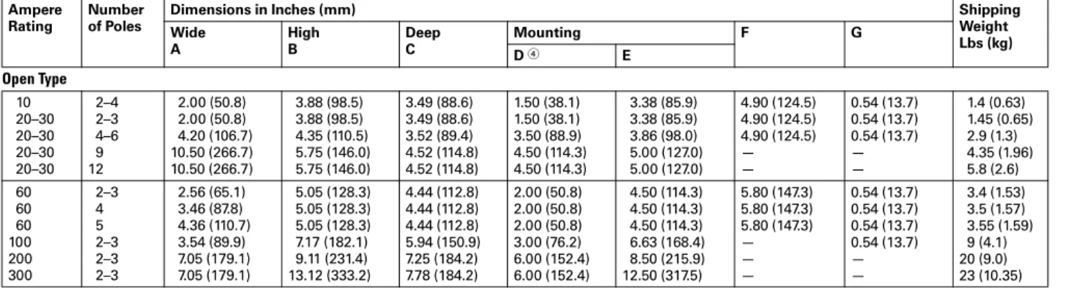
Table 30.2-3. Approximate Dimensions and Shipping Weights
4Center mounting slot at bottom on 10–30 A sizes only.
Maximum Ampere Rating 1 Number of Poles 10 20 30 60 100, 200, 300 400 2, 3, 4 2, 3, 4, 6, 9, 12 2, 3, 4, 5, 6, 9, 12 2, 3, 4 2, 5 2 2, 3, 4, 5 2, 3 G A G Top Mtd. Aux. Side Mtd. Aux. Top Mtd. Aux. Mtg. Holes for #10-32 Screws Auxiliary Contacts√ A U X A U X D F C B E Top Mtd. Aux. Top Mtd. Aux. Top Mtd. Aux. Side Mtd. Aux. 3 Mtg. Holes for #10-32 Screws Auxiliary Contacts√ A G F C A U XE D B Top Mtd. Aux. Top Mtd. Aux. Top Mtd. Aux. Side Mtd. Aux. 3 Mtg. Holes for #10-32 Screws Auxiliary Contacts√ A G F C A U XE D B Ampere Rating Number of Poles
Dimensions in Inches (mm) Shipping
Weight Lbs (kg) Wide A High B Deep C Mounting F G D 4 E Open Type 10 20–30 20–30 20–30 20–30 2–4 2–3 4–6 9 12 2.00 (50.8) 2.00 (50.8) 4.20 (106.7) 10.50 (266.7) 10.50 (266.7) 3.88 (98.5) 3.88 (98.5) 4.35 (110.5) 5.75 (146.0) 5.75 (146.0) 3.49 (88.6) 3.49 (88.6) 3.52 (89.4) 4.52 (114.8) 4.52 (114.8) 1.50 (38.1) 1.50 (38.1) 3.50 (88.9) 4.50 (114.3) 4.50 (114.3) 3.38 (85.9) 3.38 (85.9) 3.86 (98.0) 5.00 (127.0) 5.00 (127.0) 4.90 (124.5) 4.90 (124.5) 4.90 (124.5) — — 0.54 (13.7) 0.54 (13.7) 0.54 (13.7) — — 1.4 (0.63) 1.45 (0.65) 2.9 (1.3) 4.35 (1.96) 5.8 (2.6) 60 60 60 100 200 300 2–3 4 5 2–3 2–3 2–3 2.56 (65.1) 3.46 (87.8) 4.36 (110.7) 3.54 (89.9) 7.05 (179.1) 7.05 (179.1) 5.05 (128.3) 5.05 (128.3) 5.05 (128.3) 7.17 (182.1) 9.11 (231.4) 13.12 (333.2) 4.44 (112.8) 4.44 (112.8) 4.44 (112.8) 5.94 (150.9) 7.25 (184.2) 7.78 (184.2) 2.00 (50.8) 2.00 (50.8) 2.00 (50.8) 3.00 (76.2) 6.00 (152.4) 6.00 (152.4) 4.50 (114.3) 4.50 (114.3) 4.50 (114.3) 6.63 (168.4) 8.50 (215.9) 12.50 (317.5) 5.80 (147.3) 5.80 (147.3) 5.80 (147.3) — — — 0.54 (13.7) 0.54 (13.7) 0.54 (13.7) 0.54 (13.7) — — 3.4 (1.53) 3.5 (1.57) 3.55 (1.59) 9 (4.1) 20 (9.0) 23 (10.35)
April 2016 Sheet 30
22
23
24
25
26
27
28
29
30
31
32
33
34
35
36
37
38
39
40
41
42
43
Lighting Contactors
Electrically Held—CN35 011Enclosed Box Selection
Table 30.2-4. Type 1 Non-combination Lighting Contactors—Electrically Held—CN35
Table 30.2-5. Type 3R, 4/4X, 12 Non-combination Lighting Contactors—Electrically Held—CN35
Table 30.2-6. Type 1 Combination Lighting Contactors
Table 30.2-7. Type 3R, 4/4X, 12 Combination Lighting Contactors
Ampere Size
(Poles) Box No. ShippingWeight Lbs (kg)
Contactors—without Control Power Transformers
10 A (2P, 3P, 4P) 1 5 (2.3) 10 A (2P, 3P, 4P, 5P, 6P) w/top adders 2 7.3 (3.3) 10 A (9P, 10P, 12P, 20P) 3 9.5 (4.3) 20 A (2P, 3P) 1 5.2 (2.4) 20 A (2P, 3P, 4P, 5P, 6P)
w/top adders & 6P w/o top adder
2 7.3 (3.3) 20 A (9P, 10P, 12P, 20P) 3 9 (4.1) 20 A (9P, 12P) w/top adders 3 9.3 (4.2) 30 A (2P, 3P) 1 5.3 (2.4) 30 A (2P, 3P, 4P) w/top adders 2 7.3 (3.3) 30 A (5P, 6P) 3 9.0 (4.1) 30 A (5P, 6P) w/top adders 3 9.2 (4.2) 30 A (9P, 10P, 12P, 20P) 3 9.5 (4.3) 30 A (9P, 12P) w/top adders 3 9.7 (4.4) 60 A (2P, 3P) 1 7 (3.2) 60 A (2P, 3P) w/top adders 3 9.8 (4.4) 60 A (4P, 5P, 6P, 9P, 10P, 12P) 3 9.5 (4.3) 60 A (4P, 5P) w/top adders 3 10 (4.5) 100 A (2P, 3P) 4 35 (16) 100 A (4P, 5P, 6P, 9P) 4 60 (27) 200 A (2P, 3P) 4 70 (32) 200 A (4P, 5P, 6P) 10 133 (60) 300 A (2P, 3P) 10 113 (51) 300 A (4P, 5P, 6P) 10 136 (62) 400 A (2P, 3P) 10 125 (57)
Contactors—with Control Power Transformers
10 A (2P, 3P, 4P) 2 11 (5.0) 10 A (2P, 3P, 4P, 5P, 6P, 9P, 10P, 12P, 20P) w/top adders 3 13.1 (5.9) 20 A (2P, 3P, 4P, 6P) 2 11 (5.0) 20 A (2P, 3P, 4P, 5P, 6P) w/top adders 3 13.1 (5.9) 20 A (9P, 10P, 12P, 20P) 3 13.5 (6.1) 20 A (9P, 12P) w/top adders 3 13.5 (6.1) 30 A (2P, 3P, 4P) 2 12 (5.4) 30 A (2P, 3P, 4P) w/top adders 3 13.1 (5.9) 30 A (5P, 6P) 2 12.5 (5.7) 30 A (5P, 6P) w/top adders 3 13.5 (6.1) 30 A (9P, 10P, 12P, 20P) 3 13.9 (6.3) 30 A (9P, 12P) w/top adders 3 14.1 (6.4) 60 A (2P, 3P) 2 12.8 (5.8) 60 A (2P, 3P) w/top adders 3 14 (6.4) 60 A (4P, 5P, 6P, 9P, 10P, 12P) 3 14 (6.4) 60 A (4P, 5P) w/top adders 3 14.2 (6.4) 100 A (2P, 3P) 4 39 (18) 100 A (4P, 5P, 6P, 9P) 4 67 (30) 200 A (2P, 3P) 10 117 (53) 200 A (4P, 5P, 6P) 10 140 (64) 300 A (2P, 3P) 10 120 (54) 300 A (4P, 5P, 6P) 10 143 (65) 400 A (2P, 3P) 10 132 (60) Ampere Size (Poles) Box No. Shipping Weight Lbs (kg)
Contactors—without Control Power Transformers
10 A (2P, 3P, 4P, 5P, 6P) 5 12 (5.4) 10 A (9P, 10P, 12P, 20P) 7 20 (9.1) 20 A (2P, 3P, 4P, 5P) 5 12 (5.4) 20 A (6P) 5 14 (6.4) 20 A (9P, 10P, 12P, 20P) 7 20 (9.1) 30 A (2P, 3P, 4P) 5 13 (5.9) 30 A (5P, 6P) 6 14 (6.4) 30 A (9P, 10P, 12P, 20P) 7 20 (9.1) 60 A (2P, 3P, 4P) 5 13 (5.9) 60 A (5P, 6P) 6 16 (7.3) 60 A (9P, 10P, 12P) 7 22 (10) 100 A (2P, 3P) 8 49 (22) 100 A (4P, 5P, 6P, 9P) 8 57 (26) 200 A (2P, 3P) 8 110 (50) 300 A (2P, 3P) 10 113 (51) 400 A (2P, 3P) 10 125 57)
Contactors—with Control Power Transformers
10 A (2P, 3P, 4P, 5P, 6P) 5 16 (7.3) 10 A (9P, 10P, 12P, 20P) 7 20 (9) 20 A (2P, 3P, 4P, 5P) 5 16 (7.3) 20 A (6P, 9P, 10P, 12P, 20P) 7 24 (11) 30 A (2P, 3P, 4P) 6 18 (8.2) 30 A (5P, 6P) 6 18 (8.2) 30 A (9P, 10P, 12P, 20P) 7 24 (11) 60 A (2P, 3P) 6 21 (10) 60 A (4P, 5P, 6P) 6 23 (10) 60 A (9P, 10P, 12P) 7 22 (10) 100 A (2P, 3P) 8 56 (25) 100 A (4P, 5P, 6P, 9P) 8 64 (29) 200 A (2P, 3P) 8 117 (53) 300 A (2P, 3P) 10 120 (54) 400 A (2P, 3P) 10 132 (60)
Ampere Size Box No.
Shipping Weight Lbs (kg)
Electrically Held—3P Only—with or without Control Power Transformers
30 A A 35 (16)
60 A A 36 (16)
100 A C 65 (30)
200 A with disconnect switch D 110 (50) 200 A with thermal-magnetic breaker E 150 (68) 300 A E 160 (73) 400 A E 170 (77) Ampere Size (Device) Box No. Shipping Weight Lbs (kg)
Electrically Held—3P Only—with or without Control Power Transformers
30 A A 35 (16)
60 A A 36 (16)
100 A C 65 (30)
200 A with disconnect switch D 110 (50) 200 A with thermal-magnetic
breaker
E 150 (68)
300 A E 160 (73)
400 A E 170 (77)
For enclosure box dimensions, refer to Page 30.6-3.
April 2016 Sheet 30
22
23
24
25
26
27
28
29
30
31
32
33
34
35
36
37
38
39
40
41
42
43
Lighting Contactors
Electrically Held—Technical Data—CN35
012
Table 30.2-8. AC Magnet Coil Data
Table 30.2-9. DC Magnet Coil Data
■ UL Insulation Rating—Class 130 (B), 105°C temperature rise
■ Operational Limits—85–110% of rated voltage for AC coils and 80%–110% of rated voltage for DC coils
Coil Data Notes
P.U. = Pickup time is the average time taken from closing of the coil circuit to main contact touch. D.O. = Dropout time is the average time taken from opening of the coil circuit to main contact separation.
Cold = Coil data with a cold coil. Hot = Coil data with a hot coil.
All data is based on a standard contactor with no auxiliary devices and a 120 Vac or 24 Vdc magnet coil. Coil data has a ±5% range depending on the application, therefore specific data may vary.
Description Contactor Catalog Number/Size CN35AN 10 A CN35BN 20 A CN35DN 30 A CN35GN 60 A CN35KN 100 A CN35NN 200 A CN35SN 300 A CN35TN 400 A Frame size 45 mm 45 mm 45 mm 65 mm 90 mm 180 mm 180 mm 180 mm
AC Magnet Coil Data
Pickup volts—cold Pickup volts—hot Pickup voltamperes Pickup watts Sealed voltamperes Sealed watts 74% 78% 100 65 10 3.1 74% 78% 100 65 10 3.1 74% 78% 100 65 10 3.1 74% 78% 230 95 28 7.8 72% 76% 390 112 49.8 13 75% 77% 1158 240 100 27.2 75% 77% 1158 240 100 27.2 75% 77% 1158 240 100 27.2 Dropout volts—cold Dropout volts—hot Pickup time (ms) Dropout time (ms) 45% 46% 12 12 45% 46% 12 12 45% 46% 12 12 49% 50% 20 14 50% 52% 14 11 63% 64% 23 15 63% 64% 23 15 63% 64% 23 15 Coil operating range –15% to +10%
Magnet coil data UL listed rating
Class 130 (B)—105 °C Temperature Rate Operating temperature –20 °C to +65 °C Maximum operating altitude 6000 Mechanical life 20,000,000 10,000,000 6,000,000 5,000,000 5,000,000 5,000,000 Wire Range Power terminals 12–16 stranded, 12–14 solid Cu 12–16 stranded, 12–14 solid Cu 8–16 stranded 10 –14 solid Cu 3–14 (upper) &/or 6–14 (lower) Stranded or solid Cu
1/0–14 Cu 350 kcmil–6 Cu 350 kcmil–8 Cu 600 kcmil–2/0 Cu
Control Terminals 12–16 Stranded 12–14 Solid Cu
Contact Kit Part No.
Two-pole Three-Pole N/A N/A N/A N/A N/A N/A 6-65-7 6-65-8 6-43-5 6-43-6 6-44 6-44-2 6-45 6-45-2 6-45 6-45-2 Auxiliary contact rating A600, P300 See Page 30.2-5
Description Contactor Catalog Number/Size CN35AN 10 A CN35BN 20 A CN35DN 30 A CN35GN 60 A CN35KN 100 A CN35NN 200 A CN35SN 300 A CN35TN 400 A Frame size 45 mm 45 mm 45 mm 65 mm 90 mm 180 mm 180 mm 180 mm Volts 24 V
DC Magnet Coil Data
Pickup volts—hot Pickup voltamperes Pickup watts Sealed voltamperes Sealed watts 80% 3.2 76.8 0.14 3.36 80% 3.2 76.8 0.14 3.36 80% 3.2 76.8 0.14 3.36 60% 6.2 88.4 0.21 4.96 61% 12.0 288.0 0.20 4.75 61% 12.0 288.0 0.20 4.75 61% 12.0 288.0 0.20 4.75 67% 18 400.0 0.22 5.3 Dropout volts—hot Pickup time (ms) Dropout time (ms) 60% 22 17 60% 22 17 60% 22 17 29% 20 13 22% 38 14 22% 38 14 22% 38 14 25% 53 14 Maximum operating altitude 3600 2400
April 2016 Sheet 30
22
23
24
25
26
27
28
29
30
31
32
33
34
35
36
37
38
39
40
41
42
43
Lighting Contactors
Mechanically Held, 30 A, 2–12 Pole—C30CNM 013
Type C30CNM—Open
(ECC—Enclosed)
C30CNMGeneral Description
Eaton’s C30CNM 30 A mechanically held lighting contactors are designed for industrial, commercial and outdoor lighting applications where efficient control is required. The mechanically held operation ensures that the con-tactor will not switch to OFF during control power failure. It also ensures the removal of coil from the circuit for noise-free operation and the elimination of all coil losses after the contactor is latched. The control module micropro-cessor validates the control signal before operation, so it will not respond to momentary voltage spikes of noise. The operation command has a built-in 0.4 second delay to avoid multiple short-term commands that can cause contact fatigue or failure. Also, the feedback loop prevents the contactor from getting out of sequence with switches, even after power failures.Typical Specifications
Mechanically held lighting contactors are Eaton Type C30CNM or approved equal and are rated for lighting loads of 30 A. They are capable of being supplied in a 2–12 pole single unit configuration.
These contactors are designed to with-stand the large initial inrush currents of tungsten and ballast lamp loads as well as non-motor (resistive) loads without contact welding. The contactor is capable of being operated such that it will not switch to OFF during control circuit power failures.
Operation
Three-wire control is the choice for use with momentary devices allowing operation from multiple locations. A momentary pulse of energy operates the contactor while a second pulse on an alternate leg returns the contactor to its original state.
Two-wire control is the choice for single output automatic operation or for operation from single-pole devices. When voltage is applied to the input terminals the contactor is latched into position (coil is removed from the circuit while control voltage is continuously supplied). When control voltage is re-moved, the latch is disengaged and the contactor is returned to its original state.
Technical Data and Specifications
Main Power Poles
Table 30.2-10. Maximum AC Voltage and Ampere Ratings
Table 30.2-11. Maximum Horsepower Rating
Table 30.2-12. Control Module
Table 30.2-13. Other Control Module Characteristics
Auxiliary Contacts Rating:
■ 600 A, 24 Vdc, 24 VA
Ambient Temperature:
■ –13 °F to +104 °F (–25 °C to +40 °C)
Mounting Position:
■ Vertical three-point mounting only
Coil:
■ Inrush 248 VA ■ Sealed 28 VA
Wire Size
Table 30.2-14. Wire Specifications
18 AWG stranded only.
Enclosed Box Selection
Table 30.2-15. Type 1 Non-combination Lighting Contactors—C30CN 22Consult factory for combination enclosures. Table 30.2-16. Type 3R, 4X and 12 Non-combination Lighting Contactors—C30CN 3
3 Consult factory for combination enclosures. Load Type Amps Continuous Poles Single-Phase Three-Phase
Ballast 30 347 Vac 600 Vac General use 30 600 Vac 600 Vac Tungsten 20 277 Vac 480 Vac AC resistive 30 600 Vac 600 Vac
Normal Starting Duty
Volts Horsepower Single-Pole, Single-Phase 110–120 220–240 1 2 Three-Pole, Three-Phase 200–208 220–240 440–480 550–600 3 5 10 15 Input Voltage Steady-State Current at Rated Voltage (mA) Maximum VA 12–24 Vdc 42 2 24 Vac 80 5 115–120 Vac 83 12 200–277 Vac 91 30 Description Specification
Minimum pulse duration (Three-wire control module)
250 ms Maximum allowable
Leakage current
1.8 mA
EMI 35 V/m
Surge transient peak 6 kV Frequency range 40–70 Hz Component Number of Cables Wire Range (Solid or Stranded) Wire Temp. Power Poles 1 14–8 AWG 75 ºC Cu 2 14–8 AWG 1 75 ºC Cu Coil 1 or 2 18–14 AWG 60 /75 ºC Cu Control Module 1 22–12 AWG 60º/75 ºC Cu Auxiliary Contacts 1 or 2 22–12 AWG 60/75 ºC Cu Ampere Size (Poles) Box No. Shipping Weight Lbs (kg) Lighting Contactors—
without Control Power Transformers
30 A (2–12) 2 9 (4.1)
Lighting Contactors—
with Control Power Transformers
30 A (2–12) 3 13.5 (5.9) Ampere Size (Poles) Box No. Shipping Weight Lbs (kg) Lighting Contactors—
without Control Power Transformers
30 A (2–12) 6 14 (6.4)
Lighting Contactors—
with Control Power Transformers
30 A (2–12) 7 20 (9.1)
For enclosure box dimensions, refer to Page 30.6-3.
April 2016 Sheet 30
22
23
24
25
26
27
28
29
30
31
32
33
34
35
36
37
38
39
40
41
42
43
Lighting Contactors
Mechanically Held, 30 A, 2–12 Pole—C30CNM
014
Components
Electrically Held Base Contactor
Electrically Held Base Contactor The C30CNE20_0 electrically held base contactor contains a 2NO power pole as standard and will allow the addition of power poles to build an electrically held contactor up to 12 poles maximum. A mechanically held module kit can also be added to convert the electrically held contactor into a mechanically held contactor in the field.
Table 30.2-17. Electrically Held Base Contactor
1When ordering, select required contactor
by Catalog Number and replace the magnet coil alpha designation in the Catalog Number (...) with the proper Code Suffix from Table 30.2-18.
Table 30.2-18. Coil Base Voltage (Digit 8) Power Poles Catalog Number 1 2NO C30CNE200 Voltage (Digit 8) Code Suffix 115–120 V 60 Hz/110 V 50 Hz 230–240 V 60 Hz/220 V 50 Hz 460–480 V 60 Hz/440 V 50 Hz 575–600 V 60 Hz/550 V 50 Hz 200–208 V 60 Hz A B C D E 265–277 V 60 Hz/240 V 50 Hz 24 V 60 Hz/20 V 50 Hz 28 V 60Hz/24 V 50 Hz 347 V 60 Hz H T V X
Power Poles
Power PolesThe C30CNM contactor accepts up to a maximum six single- or double-pole (or combinations) power poles. These can be used to form up to:
■ 12NO poles maximum when six double-poles are used in NO positions (1–6) or 8NC poles maximum with four double-poles in the NC position (1–4) and 4NO poles with two double-poles in the 2NO positions (5–6) Table 30.2-19. Power Poles
Mechanically Held Module Kits
Conversion Kits
These kits are for converting electri-cally held contactors to mechanielectri-cally held units. Kits include control mod-ule, latch, latch cover and auxiliary contacts plus installation instructions. Conversion kits are suitable for coil voltages of 277 V and below.
Table 30.2-20. Mechanically Held Module Kits
Figure 30.2-4. C30CNM Components—Exploded View Power Poles Catalog Number Single-pole Double-pole C320PRP1 C320PRP2 Coil Volts Control Volts Catalog Number Two-Wire 24–277 Vac 110–120 Vac 200–277 Vac 24 Vac 12–24 Vdc C320MH2WA0 C320MH2WH0 C320MH2WT0 C320MH2WT1 Three-Wire 24–277 Vac 110–120 Vac 200–277 Vac 24 Vac 12–24 Vdc C320MH3WA0 C320MH3WH0 C320MH3WT0 C320MH3WT1
April 2016 Sheet 30
22
23
24
25
26
27
28
29
30
31
32
33
34
35
36
37
38
39
40
41
42
43
Lighting Contactors
Mechanically Held, 30 A, 2–12 Pole—C30CNM 015
Auxiliary Contacts
Auxiliary Contacts A mechanically held contactor with a two-wire control module uses 1NC auxiliary contact as standard for the control wiring circuit. The mechanically held contactor with a three-wire control module uses 1NO–1NC auxiliary contacts as standard for the control wiring circuit. See Table 30.2-21 for possible additional auxiliary contact configurations.
Table 30.2-21. Auxiliary Contact Configurations
Table 30.2-22. Auxiliary Contact Blocks
Replacement Parts
Magnetic Coils for the Base Contactor
Magnetic Coils Table 30.2-23. Magnetic Coils
Wiring Diagrams
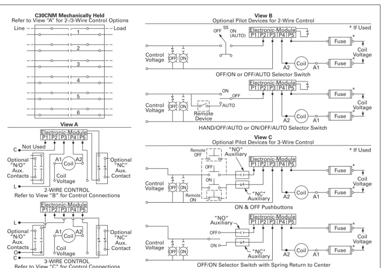
Figure 30.2-5. C30CNM Wiring Diagram
Two-Wire Three-Wire None 1NO (single-pole) 2NO (double-pole) None 1NC (double-pole) 1NO (double-pole) 1NC (double-pole) 1NO–1NC (NO single-pole NC double-pole) 2NO–1NC (double pole) 1NO–1NC (double-pole) — — Auxiliary Block Catalog Number Single-pole Double-pole C320AMH1 C320AMH2 Coil Voltage Catalog Number 115–120 V 60 Hz/110 V 50 Hz 230–240 V 60 Hz/220 V 50 Hz 460–480 V 60 Hz/440 V 50 Hz 575–600 V 60 Hz/550 V 50 Hz 200–208 V 60 Hz 9-3242-1 9-3242-2 9-3242-3 9-3242-4 9-3242-5 265–277 V 60 Hz/240 V 50 Hz 24 V 60 Hz/20 V 50 Hz 28 V 60 Hz/24 V 50 Hz 347 V 60 Hz 9-3242-6 9-3242-7 9-3242-8 9-3242-9 1 2 Line Load 3 4 5 6 C30CNE Electrically Held
View A
CONTROL
Refer to View “B” for Control Connections Optional Auxiliary Contacts Optional Auxiliary Contacts A1 A2 Coil Coil Voltage ON and OFF Pushbuttons View B
Optional Pilot Devices for Electrically Held Contactor
OFFSSAUTO * If Used OFF ON AUTO A1 L2 L1 A2 * Fuse * Fuse Remote OFF Remote ON ON ON Pushbutton OFF Pushbutton OFF Coil Auxiliary Contact Auxiliary Contact
OFF/ON or OFF/AUTO Selector Switch A1 L2 L1 A2 * Fuse * Fuse Remote Device ON OFF Coil Auxiliary Contact
OFF/ON/AUTO or HAND/OFF/AUTO Selector Switch A1 L2 L1 A2 * Fuse * Fuse Remote Device ON OFF Coil Auxiliary Contact
April 2016 Sheet 30
22
23
24
25
26
27
28
29
30
31
32
33
34
35
36
37
38
39
40
41
42
43
Lighting Contactors
Mechanically Held, 30 A, 2–12 Pole—C30CNM
016
Figure 30.2-6. C30CNM Wiring Diagram
Dimensions
Figure 30.2-7. Approximate Dimensions in Inches (mm) 1 2 Line Load 3 4 5 6 C30CNM Mechanically Held
Refer to View “A” for 2-/3-Wire Control Options
2-WIRE CONTROL
Refer to View “B” for Control Connections
View A Optional “N/O” Aux. Contacts Optional “NC” Aux. Contact P1 A1 C L A2 P2 P3
Electronic-Module
Not Used P4 P5 Coil Coil Voltage 3-WIRE CONTROL
Refer to View “C” for Control Connections
Optional “N/O” Aux. Contacts Optional “NC” Aux. Contact P1 A1 L C O A2 P2 P3
Electronic-Module
P4 P5
Coil
Coil
Voltage
OFF/ON or OFF/AUTO Selector Switch
View B
Optional Pilot Devices for 2-Wire Control
P1
A1 A2
P2 P3
Electronic-Module
P4 P5 Fuse Fuse Coil Voltage Control Voltage OFF ON (AUTO) SS Coil
HAND/OFF/AUTO or ON/OFF/AUTO Selector Switch
P1
A1 A2
P2 P3
Electronic-Module
P4 P5 Fuse Fuse Coil Voltage * * * * * * * * * If Used * If Used Control Voltage Remote Device OFF ON AUTO Coil
ON & OFF Pushbuttons View C
Optional Pilot Devices for 3-Wire Control
P1
A1 A2
P2 P3
Electronic-Module
P4 P5 Fuse Fuse Coil Voltage Control Voltage Coil ”NO“ Auxiliary ”NC“ Auxiliary OFF ON Remote OFF Remote ON
OFF/ON Selector Switch with Spring Return to Center
P1
A1 A2
P2 P3
Electronic-Module
P4 P5 Fuse Fuse Coil Voltage Control Voltage Coil ”NO“ Auxiliary ”NC“ Auxiliary ON OFF OFF ON OFF ON OFF ON OFF ON ON ON ON ON ON ON P1 A1 A2 P2 P3 P4 P5 P1 P2 P3 P4 P5 .35 (9.0) NOTE:
1 Mounting dimensions remain the same
for 1 to 12 poles.
2 Line and Load terminals are interchangeable.
3 Up to 2NO and 2NC auxiliary contacts can be
added onto the base product.
4 Same power pole can be configured as
NO type or NC type in pole positions 1 – 4;
NO type only in positions 5 – 6.
SIDE VIEW TOP VIEW END VIEW
Power Pole Optional Power Pole Optional “NC” Aux Contacts Optional “NO” Aux Contacts Mounting Holes Accept #10 Screws 2 “NO” Aux Contacts 1 “NO” Aux Contact 2 “NC” Aux Contacts 1 “NC” Aux Contact 3.86 (98.0) .35 (9.0) 4.18 (106.2) 3.75 (95.3) 6.50 (165.1) 3.86 (98.0) .59 (14.9) 7.39 (187.6) .22 (5.5)
April 2016 Sheet 30
22
23
24
25
26
27
28
29
30
31
32
33
34
35
36
37
38
39
40
41
42
43
Lighting Contactors
Magnetically Latched (Mechanically Held)—A202 017
A202–Open (ECL04–Enclosed)
60 Ampere Size
General Description
AC lighting contactors provide a safe convenient means for local or remote switching of relatively large tungsten, fluorescent or mercury arc lamp loads. They are also suitable for low pressure and high pressure sodium lamp loads. These lighting contactors are designed to withstand the large initial inrush currents of tungsten lamp loads with-out contact welding. They are full rated and do not require derating as do stan-dard motor control contactors.
Operation (Magnetic Latch)
A permanent magnet is built into the contactor structure that will maintain the contactor in its energized state indefinitely without using control power. When energized, a DC current is applied to the latch coil producing a magnetic field that reinforces the polarity of the permanent magnet, pulling in the contactor. The current to the coil is disconnected by the coil clearing interlock. In order to drop out the contactor, it is necessary to apply a field through the STOP coil in the reverse direction to the permanent magnet. This momentarily cancels the magnetic attraction and the contactor drops out.Enclosures
Open and NEMA Types 1, 3R, 4X and 12.
Specifications
■ Terminals: ❑ All except
30 A devices . . . Al/Cu ❑ 30 A devices . . . Cu only ■ Ballast load 600 Vac, breaking
all lines
■ Tungsten lamp loads, maximum volts: ❑ Line-to-line. . . 480 Vac ❑ Line-to-neutral. . . 277 Vac
Typical Specifications
Magnetically-held lighting contactors are Eaton’s Type A202 or approved equal for lighting loads of 30–400 A. Magnetically-held combination lighting contactors are Type ECL15 (breaker) or ECL13 (fusible) or approved equal for loads of 30–200 A when integral short circuit protection is required.
These contactors are designed to withstand the large initial inrush currents of tungsten and ballast lamp loads as well as non-motor (resistive) loads without contacts welding. The contactors are capable of being “magnetically held” via a magnetic latch design using a permanent
magnet. The contactor shall be operated by a RUN signal and a STOP signal preventing the contactor from switching to “OFF” during control circuit power failures.
Table 30.2-24. Ratings—Latched AC Lighting Contactors
Table 30.2-25. Non-Combination Lighting Contactors—6 to 12 Pole
Figure 30.2-8. Open Type
Figure 30.2-9. Connection Diagram
For enclosure box dimensions, refer to Page 30.6-3.
Holding Circuit Auxiliary Contact or Pushbutton Station not Included Continuous Amperes (Enclosed) Number of Poles 30 60 100 2, 3, 4, 5, 6, 8, 10, 12 2, 3, 4, 5, 6, 8, 10, 12 2, 3, 4, 5, 6, 8, 10, 12 200 300 400 2, 3, 4, 5, 6, 8, 10, 12 2, 3 2, 3 Continuous Amperes (Enclosed) Number of Poles Pole Configuration Dimensions in Inches (mm) Open Type Wide A High B 30 6 8 10 12 3 x 3 4 x 4 5 x 5 4 x 4 x 4 7.13 (181.1) 7.13 (181.1) 10.63 (270.0) 12.38 (314.5) 4.46 (113.3) 4.46 (113.3) 4.46 (113.3) 6.88 (174.8) 60 6 8 10 12 3 x 3 4 x 4 5 x 5 5 x 5 x 2 7.13 (181.1) 10.63 (270.0) 10.63 (270.0) 15.00 (381.0) 4.46 (113.3) 4.46 (113.3) 4.46 (113.3) 6.88 (174.8) 100 6 8 10 12 3 x 3 5 x 3 5 x 5 5 x 5 x 2 9.75 (247.7) 12.38 (314.5) 15.00 (381.0) 34.13 (866.9) 6.88 (174.8) 6.88 (174.8) 6.88 (174.8) 27.50 (698.5) 200 6 8 10 12 3 x 3 5 x 3 5 x 5 5 x 5 x 2 9.75 (247.7) 12.38 (314.5) 15.00 (381.0) 34.13 (866.9) 6.88 (174.8) 6.88 (174.8) 6.88 (174.8) 27.50 (698.5) C B A
Connections for Control Stations
Elementary Diagram Separate Control
Connections for Contactor Front View Diagram Off 2 3 1 1 Momentary Pushbutton Top Auxiliary Contact “C” (Not Supplied)
L2 Control Module Line When Supplied Red Maintained Pushbutton Fig. A On Off 2 3 Line M Load Off Momentary Pushbutton 1 1 1 3 2 Off On Maintained Pushbutton N.O. N.C. Top Red White M M “C” L2 Red Red Black Auxiliary Contact (When Used) Connect separate control lines to the No. 1 terminal on the remote control station and to the “L2” terminal on the contactor.
Auxiliary Contact (When Used) Poles to Load Black 3 3 N.C. N.O. 2 2 White On Fig. B Fig. 1 8 8 8 8 8 M On OffM ~ ~ + – Red M M M M ~ ~ + – On Control Voltage Lines
On
April 2016 Sheet 30
22
23
24
25
26
27
28
29
30
31
32
33
34
35
36
37
38
39
40
41
42
43
Lighting Contactors
Magnetically Latched (Mechanically Held)—A202
018
Enclosed Box Selection
Table 30.2-26. Type 1 Non-combination Lighting Contactors—Magnetically Latched—A202Table 30.2-27. Type 3R, 4/4X, 12 Non-combination Lighting Contactors— Magnetically Latched—A202
Table 30.2-28. Type 1 Combination Lighting Contactors
Table 30.2-29. NEMA 3R, 4/4X, 12 Combination Lighting Contactors Ampere Size (Poles) Box No. Shipping Weight Lbs (kg)
Contactors—without Control Power Transformers
30 A (2P, 3P, 4P, 5P) 2 8.5 (3.9) 30 A (6P, 8P, 10P, 12P) 3 13 (5.9) 30 A (20P) 4 35 (16) 60 A (2P, 3P, 4P, 5P) 2 8.7 (3.9) 60 A (6P, 8P, 10P, 12P) 3 13.5 (6.1) 60 A (20P) 4 40 (18) 100 A (2P, 3P, 4P, 5P) 4 40 (18) 100 A (6P, 8P, 10P, 12P) 9 85 (39) 100 A (20P) 9 100 (45) 200 A (2P, 3P, 4P, 5P) 4 46 (21) 200 A (6P, 8P, 10P, 12P) 9 95 (43) 200 A (20P) 9 110 (50) 300 A (2P, 3P) 10 115 (52) 400 A (2P, 3P) 10 125 (57)
Contactors—with Control Power Transformers
30 A (2P, 3P, 4P, 5P) 2 12.5 (5.7) 30 A (6P, 8P, 10P, 12P) 3 17 (7.7) 30 A (20P) 4 39 (18) 60 A (2P, 3P, 4P, 5P) 2 12.7 (5.8) 60 A (6P, 8P, 10P) 3 17.5 (7.9) 60 A (12P) 9 87 (39) 60 A (20P) 4 44 (20) 100 A (2P, 3P, 4P, 5P) 4 47 (21) 100 A (6P, 8P, 10P, 12P) 9 92 (42) 100 A (20P) 9 107 (49) 200 A (2P, 3P, 4P, 5P) 4 53 (24) 200 A (6P, 8P, 10P, 12P) 9 102 (46) 200 A (20P) 9 117 (53) 300 A (2P, 3P) 10 122 (55) 400 A (2P, 3P) 10 132 (60) Ampere Size (Poles) Box No. Shipping Weight Lbs (kg)
Contactors—without Control Power Transformers
30 A (2P, 3P, 4P, 5P) 5 13 (5.9) 30 A (6P, 8P, 10P, 12P) 7 21 (10) 30 A (20P) 8 46 (21) 60 A (2P, 3P, 4P, 5P) 5 14 (6.4) 60 A (6P, 8P, 10P, 12P) 7 22 (10) 60 A (20P) 8 48 (22) 100 A (2P, 3P, 4P, 5P) 8 50 (23) 100 A (6P, 8P, 10P,12P) 9 58 (26) 100 A (20P) 10 100 (45) 200 A (2P, 3P, 4P, 5P) 8 52 (24) 200 A (20P) 10 105 (48) 300 A (2P, 3P) 10 113 (51) 400 A (2P, 3P) 10 125 (57)
Contactors—with Control Power Transformers
30 A (2P, 3P) 6 15 (6.8) 30 A (4P, 5P, 6P, 8P, 10P, 12P) 7 28 (13) 30 A (20P) 8 54 (25) 60 A (2P, 3P) 6 16 (7.3) 60 A (4P, 5P, 6P, 8P, 10P, 12P) 7 29 (13) 60 A (20P) 8 55 (25) 100 A (2P, 3P, 4P, 5P) 8 57 (26) 100 A (6P, 8P, 10P, 12P) 9 65 (30) 100 A (20P) 10 112 (51) 200 A (2P, 3P, 4P, 5P) 8 59 (27) 300 A (2P, 3P) 10 120 (54) 400 A (2P, 3P) 10 132 (60)
Ampere Size Box No.
Shipping Weight Lbs (kg)
Magnetically Latched—Non-reversing (3P Only)— with or without Control Power Transformers
30 A A 35 (16)
60 A A 36 (16)
100 A C 65 (30)
200 A with disconnect switch D 110 (50) 200 A with thermal-
magnetic breaker
E 150 (68)
300 A E 140 (64)
400 A E 190 (86)
Ampere Size Box No.
Shipping Weight Lbs (kg)
Magnetically Latched—Non-reversing (3P Only)— with or without Control Power Transformers
30 A A 35 (16)
60 A A 36 (16)
100 A C 65 (30)
200 A with disconnect switch D 110 (50) 200 A with thermal-
magnetic breaker
E 150 (68) 300 A with disconnect switch 72” 375 (170) 300 A with thermal-
magnetic breaker
E 160 (73) 400 A with disconnect switch 72” 425 (193) 400 A with thermal-
magnetic breaker
E 210 (95)
For enclosure box dimensions, refer to Page 30.6-3.
April 2016 Sheet 30
22
23
24
25
26
27
28
29
30
31
32
33
34
35
36
37
38
39
40
41
42
43
Lighting Contactors
Electrically Held and Magnetically Latched Combination Lighting, Three-Pole Only—Type ECL 019
Combination Lighting
Contactors
Types ECL12, ECL13, ECL14
and ECL15
General Description
Catalog Number ECL12, ECL13, ECL14 and ECL15 combination lighting con-tactors offer convenient installation of switching and overcurrent protection in a single enclosure. Combination lighting contactors are ideally suited for industrial and commercial lighting applications or where a lighting circuit may have to be disconnected for peri-odic maintenance. They may also be applied on resistance heating loads.
Typical Specifications
Magnetically latched combination lighting contactors are Eaton’s Type
ECL15 (breaker) or ECL13 (fusible) or approved equal for loads of 30–200 A when integral short-circuit protection is required.
These contactors are designed to withstand the large initial inrush currents of tungsten and ballast lamp loads as well as non-motor (resistive) loads without contact welding. The contactors are capable of being “magnetically held” via a magnetic latch design using a permanent magnet. The contactor shall be operated by a RUN signal and a STOP signal preventing the contactor from switch-ing to “OFF” durswitch-ing control circuit power failures.
Electrically held combination lighting contactors are Eaton Type ECL14 (breaker) or ECL12 (fusible) or approved equal for loads of 30–400 A when integral short-circuit protection is required.
These contactors shall be designed to withstand the large initial inrush cur-rents of tungsten and ballast lamp loads as well as non-motor (resistive) loads without contact welding. Contactors shall be capable of accepting up to eight auxiliary contacts—top and/or side up to 60 A and side only up to 400 A. Contac-tors shall be capable of being operated by AC or DC control.
Features
■ Disconnect devices—either a Series C circuit breaker or a fusible disconnect switch
■ Handle mechanism—flange mounted
■ UL listed
■ UL service entrance approved for NEMA 3R outdoor enclosure ■ Extra room for modifications such
as a 24-hour time clock
Catalog Number Selection
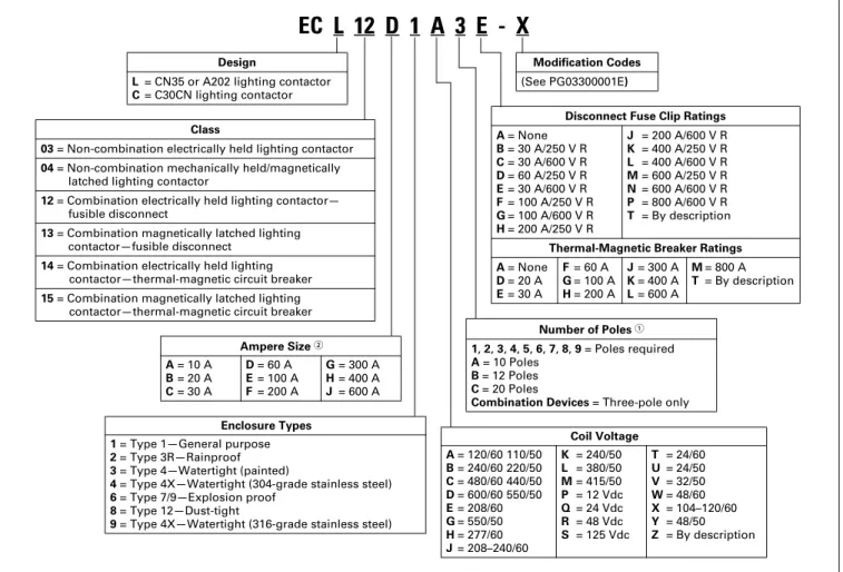
Table 30.2-30. Enclosed Lighting Contactor Catalog Numbering System
1For normally closed poles, see PG03300001E. 2C30CN available in 30 A only.
EC L 12 D 1 A 3 E - X
DesignL= CN35 or A202 lighting contactor
C= C30CN lighting contactor
Class
03 = Non-combination electrically held lighting contactor
04 = Non-combination mechanically held/magnetically latched lighting contactor
12 = Combination electrically held lighting contactor— fusible disconnect
13 = Combination magnetically latched lighting contactor—fusible disconnect
14 = Combination electrically held lighting contactor—thermal-magnetic circuit breaker
15 = Combination magnetically latched lighting contactor—thermal-magnetic circuit breaker
Ampere Size 2 A= 10 A B= 20 A C= 30 A D= 60 A E= 100 A F= 200 A G= 300 A H= 400 A J= 600 A Enclosure Types 1 = Type 1—General purpose
2 = Type 3R—Rainproof
3 = Type 4—Watertight (painted)
4 = Type 4X—Watertight (304-grade stainless steel)
6 = Type 7/9—Explosion proof
8 = Type 12—Dust-tight
9 = Type 4X—Watertight (316-grade stainless steel)
Coil Voltage A= 120/60 110/50 B= 240/60 220/50 C= 480/60 440/50 D= 600/60 550/50 E= 208/60 G= 550/50 H= 277/60 J= 208–240/60 K = 240/50 L = 380/50 M= 415/50 P = 12 Vdc Q = 24 Vdc R = 48 Vdc S = 125 Vdc T = 24/60 U = 24/50 V = 32/50 W= 48/60 X = 104–120/60 Y = 48/50 Z = By description Modification Codes (See PG03300001E) Number of Poles 1 1, 2, 3, 4, 5, 6, 7, 8, 9 = Poles required A = 10 Poles B = 12 Poles C = 20 Poles
Combination Devices = Three-pole only
Disconnect Fuse Clip Ratings A= None B= 30 A/250 V R C= 30 A/600 V R D= 60 A/250 V R E= 30 A/600 V R F= 100 A/250 V R G= 100 A/600 V R H= 200 A/250 V R J = 200 A/600 V R K = 400 A/250 V R L = 400 A/600 V R M= 600 A/250 V R N= 600 A/600 V R P = 800 A/600 V R T = By description
Thermal-Magnetic Breaker Ratings A= None D= 20 A E= 30 A F= 60 A G= 100 A H= 200 A J= 300 A K= 400 A L= 600 A M= 800 A T = By description
April 2016 Sheet 30
22
23
24
25
26
27
28
29
30
31
32
33
34
35
36
37
38
39
40
41
42
43
Lighting Contactors
Electrically Held and Magnetically Latched Combination Lighting, Three-Pole Only—Type ECL
020
Table 30.2-31. Ratings—Latched ELC15 Series C Circuit Breaker Disconnect
Table 30.2-32. ELC13—Fusible Disconnect Switch
Table 30.2-33. Ratings—Electrically-held ELC14 Series C Circuit Breaker Disconnect
1UL ballast and resistive ratings only. Table 30.2-34. ELC12—Fusible Disconnect Switch
2UL ballast and resistive ratings only. Continuous Amperes (Enclosed) Circuit Breaker Ampere Rating System Voltage 30 60 100 200 30 60 100 200 600 600 600 600 Continuous Amperes (Enclosed) Fuse Clip Ampere Rating System Voltage 30 60 100 200 30 60 100 200 250, 600 250, 600 250, 600 250, 600 Continuous Amperes (Enclosed) Circuit Breaker Ampere Rating System Voltage 30 60 100 30 60 100 600 600 600 200 300 400 1 200 300 400 600 600 600 Continuous Amperes (Enclosed) Fuse Clip Ampere Rating System Voltage 30 60 100 30 60 100 250, 600 250, 600 250, 600 200 300 400 2 200 300 400 250, 600 250, 600 250, 600
Table 30.2-35. Factory Modifications
Description Enclosure Used On
Standard Combination
Control transformers:
480 to 120 V control transformer 100 VA extra capacity transformer 200 VA extra capacity transformer
240 to 120 V control transformer with fuse in holder 208 to 120 V control transformer with fuse in holder 415 to 110 V control transformer with fuse in holder 277 to 120 V control transformer with fuse in holder
Any ■ ■ ■ ■ ■ ■ ■ ■ ■ ■ ■ ■ ■ ■ Lightning arrester Undervoltage relay On-off pushbutton
Hand-off-auto selector switch
Any
■
■ ■■
Addition of photoelectric receptacle and relay with photo cell Installed (two-wire circuit)
—
■ ■
24-hour time clock, 120 V
24-hour time clock with day omission, 120 V 7-day time clock, 120 V
Cover plate for use in place of watertight hub on enclosure top
— ■ ■ ■ ■ ■ ■ ■ ■
April 2016 Sheet 30
22
23
24
25
26
27
28
29
30
31
32
33
34
35
36
37
38
39
40
41
42
43
Motor Starters—Electromechanical
Freedom Line—General Description 021
NEMA Motor Starters
Freedom Series
NEMA AN19DN0A5E005 NEMA Size 1
General Description
The Freedom Series starters and contactors listed in this catalog feature a compact, space-saving design and high strength, impact and temperature-resistant insulating materials. Starters and contactors are available in the NEMA (National Electrical Manufacturers’ Association) style. The NEMA devices are sized based on traditional NEMA classifications.
Features
Freedom NEMA
■ Adjustable bimetallic ambient compensated overload relays with interchangeable heater packs—available in three basic sizes, covering applications up to 900 hp— reducing the number of different contactor/overload relay combina-tions that have to be stocked. Fixed heater overloads are optional ■ Electronic overload relay (C440)
available as a stand-alone unit and assembled with a Freedom contactor
■ A full line of snap-on accessories— top and side mounted auxiliary contacts, solid-state and pneumatic timers, etc.
■ Straight-through wiring—line lugs at top, load lugs at bottom
■ Horizontal or vertical mounting on upright panel for application freedom
■ Screw type power terminals have captive, backed-out self-lifting pressure plates with ± screws— reduced wiring time
■ Accessible terminals for easy wiring. Optional fingerproof shields avail-able to prevent electrical shock ■ Top located coil terminals
conve-nient and readily accessible. 45 mm contactor magnet coils have three terminals, permitting either top or diagonal wiring—easy to replace European or U.S. style starters or contactors without changing wiring layout
■ Designed to meet or exceed NEMA, UL, CSA, VDE, BS and other interna-tional standards and listings ■ American engineering—built by
Eaton, using the latest in statistical process control methods to pro-duce high quality, reliable products ■ Sized based on standard NEMA
classifications
■ Easy coil change and inspectable/ replaceable contacts
■ Available in open and NEMA Type 1, 3R, 4/4X and 12 enclosures
Standards and Certifications
■ Standard: Designed to meet orexceed UL, NEMA and CSA ■ UL listed: UL File #E1491, Guide
#NLDX—Open; UL File #E176513— Enclosed Combination Motor Con-trollers; UL File #E19224—Enclosed Non-Combination Motor Controllers; UL File #E195239—Enclosed Power Conversion Equipment
■ CSA certified: CSA File #LR353, Class #321104 Open and NEMA 1 Enclosed
Certified Type 2 Coordination
Eaton’s Freedom Series NEMA start-ers are now UL certified to achieve IEC 947 Type 2 coordination against 100,000 A short-circuit fault currents. Any brand of properly selected fuse can be used. Type 2 coordination means that the starter will be suitable for further use following a short-circuit fault.
Short-Circuit Protection
Fuses and inverse-time circuit breakers may be selected per Article 430, Part D of the National Electrical Code® to protect motor branch circuits from fault conditions. If higher ratings or settings are required to start the motor, do not exceed the maximum as listed in Exception No. 2, Article 430.52.