AutoMicromanager: A microscopy scripting toolkit for LABVIEW and other
programming environments
Brian Alan Ashcroft, and Tjerk Oosterkamp
Citation: Review of Scientific Instruments 81, 113708 (2010); doi: 10.1063/1.3499370
View online: http://dx.doi.org/10.1063/1.3499370
View Table of Contents: http://aip.scitation.org/toc/rsi/81/11
AutoMicromanager: A microscopy scripting toolkit for
LABVIEW
and other
programming environments
Brian Alan Ashcroft and Tjerk Oosterkamp
Department of Physics, Leiden University, 2 Niels Bohrweg, 2333 CS Leiden, The Netherlands
共Received 11 June 2010; accepted 20 September 2010; published online 23 November 2010兲
We present a scripting toolkit for the acquisition and analysis of a wide variety of imaging data by
integrating the ease of use of various programming environments such as LABVIEW, IGOR PRO,
MATLAB,SCILAB, and others. This toolkit is designed to allow the user to quickly program a variety of standard microscopy components for custom microscopy applications allowing much more flexibility than other packages. Included are both programming tools as well as graphical user interface classes allowing a standard, consistent, and easy to maintain scripting environment. This programming toolkit allows easy access to most commonly used cameras, stages, and shutters through the Micromanager project so the scripter can focus on their custom application instead of boilerplate code generation. © 2010 American Institute of Physics.关doi:10.1063/1.3499370兴
I. INTRODUCTION
Setting up a custom microscopy solution often requires a
period in whichLABVIEWor some other programming
envi-ronment is used to program the required behavior for the components making up the experiment. This process often requires assembling a lot of codes to set up the microscope, camera, stage, shutters, and other equipment on the table. This can require a lot of troubleshooting or result in a code that can only be used for that one application. There are already many commercial microscopy software solutions in the market, allowing acquisition and analysis of images as well as control over a commercial microscope. These pack-ages are limited in two important ways. First, they are often proprietary, making them both expensive and difficult to change. Second, they are often single purposed, mostly either for a certain brand of cameras, or only as a control for cam-eras in general. Examples of software packages that are
de-signed to run scientific cameras within aLABVIEW
environ-ment include SCIENTIFIC IMAGING TOOLKIT,1 HCIMAGE,2
SIDX,3or DIGITAL OPTICS.4Some other projects are trying to provide generalized microscopy support. These include CAMACQJ,5 MOTMOT,6 and SCANIMAGE,7 but these are still specialized for their particular programming language or pur-pose. AutoMicromanager attempts to replace these packages with a universal programming interface to all scientific mi-croscopy devices by providing a consistent scripting inter-face to the Micromanager8project.
There are a number of software packages on the market that provide a complete microscopy control setup. These
in-clude METAMORPH and METAVUE 共Ref. 9兲 共Molecular
De-vices, CA, USA兲, NIS-ELEMENTS 共Ref. 10兲 共Nikon, NY,
USA兲,MICROSUITE 共Ref.11兲 共Olympus, Tokyo, Japan兲,LAS
共Ref. 12兲 共Leica, Germany兲, IMAGE-PRO 共Ref. 13兲 共Media
Cybernetics, MD, USA兲, IMAGING WORKBENCH 共Ref. 14兲
共Indec Imaging, CA, USA兲, and IP LABORATORY共
Scanalyt-ics, MD, USA兲. All of these packages are powerful suites
designed to make microscopy possible. They provide a num-ber of drawbacks for the microscopy user who wishes to develop new solutions, and may not allow the ability to swap
various microscopy components seamlessly. In addition, most of these solutions will not work directly within the LABVIEW environment which is popular among researchers for its ease of use and instrument control power.
In order to solve this problem, the Micromanager project has been attempting to build a constant application program-ming interface共API兲that can take the complexities of hard-ware programming and provides a constant and easy to use interface for any application. The Micromanager project uses JAVAto program its graphical user interface共GUI兲.JAVAis a powerful programming language, but lacks the ability to
in-terface with many other programming languages, notably
LA-BVIEWandIGOR PRO. In addition, the Java Native Interface can make importing native libraries difficult. We present a solution that leverages the power of the Micromanager plat-form to most of the common scripting and image analysis scripting languages. AutoMicromanager has been tested with LABVIEW 共National Instruments, TX, USA兲,SCILAB,15
MAT-LAB共The Mathworks, MA, USA兲, MATHEMATICA共Wolfram
Research, IL, USA兲, IGORPRO,16 共D兲COM AUTOMATION, and PYTHON共Ref. 17兲 共using SciPy18兲.
AutoMicromanager was created with C#, a .Net lan-guage from Microsoft. The .Net framework allows a great number of programming languages and interfaces to work together including C#, Visual Basic, C⫹⫹, Iron Python, and Ruby, as well as many more. C#, a language that relies on
the .Net framework, was chosen for its power 共the unsafe
context兲, flexibility, and for its similarity withJAVA.
II. OVERVIEW OF SUITE
The software consists of five layers as shown in Fig. 1. For the general user, however, only the device objects and the screen GUI layers will matter. These layers provide con-trol over the devices in a microscopy solution. For a full explanation, the bottom layer consists of a number of
hard-ware adapters, which have been created using C⫹⫹ either
by the Micromanager project itself, hardware vendors, or in-dependent laboratories such as ours. These hardware adapt-ers take care of the difficult task of meshing high
mance C⫹⫹ routines with the rest of the control software. The hardware adapters are capably maintained by the Micro-manager project. The next layer is the MicroMicro-manager API forming the middle layer. It controls all the adapters, envi-ronment, and so forth. The following layer is the AutoMicro-manager layer. This program controls all of the interactions with scripts, the opening and saving of microscopy setups, and a host of other operations. It encapsulates all the devices
into easy to use chunks that can be controlled by LABVIEW
and other programs. The last layer is the user interface layer. This can either be a set of buttons provided by your custom Labview FrontPage, a custom script for application specific control, or one of the many generic GUIs provided within the AutoMicromanager system which have been designed to run withinLABVIEW,共D兲COM, orACTIVEXcontexts.
The arrangement of these distinct and independent layers of control of the microscope provides the user with the most control and ease of use. If the user only wishes to provide
custom LABVIEW control of one component of the system,
then all the other components can be controlled using the default interfaces provided.
III. APPLICATION WITHINLABVIEW
LABVIEW is the primary target of AutoMicromanager at
this time. LABVIEW has excellent facilities to communicate
with the .Net framework and thisLABVIEWfeature has been
exploited to provide a powerful set of tools directly into the LABVIEW environment. The first step is to import the .Net controls into theLABVIEWenvironment. The installation pro-gram installs the controls in the Controls Menu accessible from the front page by right clicking on the front page. The
NIEasyCore 共the interface between AutoMicromanager and
LABVIEW兲 should be placed on the FrontPage to start pro-gramming.
AutoMicromanager has many modes of use as has been detailed in the extensive tutorial file available from http:// labviewmicroman.sourceforge.net/. The first mode allows all
devices to be manually specified in the LABVIEW program.
The second and easier method is to load a hardware configu-ration file into AutoMicromanager as shown in brief here. The hardware configuration file can be created from the stan-dalone program or from the hardware configuration wizard included in the installation package. The scripter should place the NIEasyCore, PictureBoard, and AllDeviceHolder controls on the FrontPage of a blank VI. Now the VI is ready to be wired.
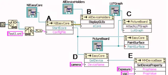
A. Basic setup
The routine “StartEcore” is used to start the Microman-ager and AutoMicromanMicroman-ager programs. It takes the location of a configuration file as input, as shown in Fig.2共a兲. This file describes all the microscopy hardware, the default set-tings of the hardware, channel setset-tings, and other microscopy environment settings. This file is not the same as the Micro-manager configuration files and can be generated by a VI that is included in the installation package, or by the standalone application. Once all this information is loaded, the informa-tion is sent to the AllDeviceHolder 关Fig. 2共b兲兴 which will arrange all the device GUI controls. The user can now inter-act with the microscopy environment.
FIG. 1. 共Color online兲 Schematic that shows the modular design of the AutoMicromanager microscopy toolkit. Micromanager interacts with low level C⫹⫹hardware adapters and AutoMicromanager allows all the func-tions to be easily accessed from most available scripting languages at the top level or through the internal GUI controls.
FIG. 2. 共Color online兲 共a兲 LABVIEW code to start AutoMicromanager, load a hardware configuration file, and start the microscope. 共b兲Code to load all the device GUI controls for user input. 共c兲Code to attach a LUT table to the image and then specify the desired im-age output surface共PaintSurface兲.共d兲 Code to request a script interface to the camera device共named in the hard-ware configuration file兲. 共e兲 Code to set the camera exposure to 100 ms.
Finally, the PaintSurface and the look up table
共LUTGraph兲are registered with NIEasyCore so the
Micros-copy images can be easily displayed, as shown in Fig.2共c兲. This tells the program to send all the images to this surface
without the need forLABVIEW to intervene. This setup will
allow the LABVIEW VI to control a number of microscopy
devices, acquire images, and script customLABVIEW
micros-copy solutions.
B. Device control
It may be desirable to control one or more of the
micros-copy devices from within theLABVIEWprogram. This is
ac-complished by asking the NIEasyCore for the desired device that has been registered with the hardware configuration file.
As shown in Fig. 2共d兲, GetDevice can be called after the
configuration file is loaded with the name of the desired de-vice. The name of the device is specified in the hardware configuration file. It is then possible to change the micros-copy device properties directly fromLABVIEW. In Fig.2共e兲, it is shown how to change the exposure on a camera. All prop-erties are changed using strings. Any devices that are defined within the AutoMicromanager toolkit can be changed by this method.
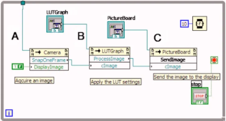
C. Image manipulation
Some scripting solutions may wish to examine or ma-nipulate the images that are being acquired. This eventuality can be handled by notifying NIEasyCore to send images to theLABVIEWprogram. This process is slightly more compli-cated than the control of the microscopy devices, as was shown in Figs.3and4. In the first case of Fig.3, the camera device is requested from NIEasyCore and then the camera is
requested to acquire an image 关Fig. 3共b兲兴 and present the
image on the screen关Fig. 3共c兲兴. The image’s pixels can be
converted into a LABVIEW array for easy manipulation as
described in the tutorials.
In Fig.4, theLABVIEW program may wish to allow the
AutoMicromanager program to perform all the user interac-tions. The scripter must start AutoMicromanager关Fig.4共a兲兴
and then notify AutoMicromanager that it wishes to receive notifications共4B兲. When a notification occurs共4C兲, the script can get the image共4D兲, manipulate the image共4D兲, and then send the image back to autoMicromanager for display共4E兲. First, there is a helper control called the NIImageProces-sor that handles all the communication of images. This is registered with NIEasyCore so it can begin to get images. ThenLABVIEWworks in a loop checking whether there is an
image ready. Once an image appears, LABVIEWcollects the
image with GetImage, manipulates the image 共in this case
saving it to disk兲, and then returns the image with PutImage and then notifies AutoMicromanager to continue with Imag-esAreProcessed. Further image processing options are avail-able, and the CoreImage class contains a number of func-tions to do basic image processing, background subtraction, and so forth.
IV. OTHER APPLICATIONS
A.PYTHON
The standard Micromanager distribution can already be used with PYTHON, but the ease of integrating .Net projects withPYTHON allows AutoMicromanager to also be used in this programming environment. The Python.Net project
al-lows a user to run .Net code in a native PYTHON
environ-ment. This allows access to the Python共x,y兲 and the other
scientific libraries available in the PYTHON world. An
ex-ample of script is included that shows how to perform a fast Fourier transform on the images acquired from the camera using SciPy in the tutorial section. The conversion from a .Net array to a SciPy array is still time consuming, and a new solution for this performance bottleneck is being completed for future versions.
B. Interior scripting„IGOR PRO/SCILABexamples…
BothIGOR PROandSCILABprovide interfaces that can be accessed by a client program to perform actions on data sets and to run simple programs. The standalone program pro-vides a method to access these programs from within the AutoMicromanager environment. In this manner, the user can access data and then the image processing and data analysis can be performed from these powerful programs.
This method can be used withMATLAB as well as any other
programming language that provides automation. FIG. 3. 共Color online兲Code to manually acquire image from camera for
manipulation or display.共a兲Ask camera to acquire one image,共b兲attach a LUT graph to the image, and共c兲display the image on a PaintSurface.
This feat is performed by starting the standalone appli-cation with a scripting form added with the hardware setup
tool or from the View menu item. APYTHONscripting engine
is included to handle the images and devices. This engine is already set with both a NIEasyCore object as has been de-fined in the other examples. The sample program is shown in
Fig.5. The standalone program has already loaded a
hard-ware config file and the script shows an example of acquiring an image or device from AutoMicromanager and then send-ing the information toSCILABfor analysis.
C.ACTIVEXcontrol based solutions
Finally, care has been taken to include a facility to allow
any scripting language that can be hosted as anACTIVEXor
共D兲COMcontrol to be used within the framework of the stan-dalone application. Many popular and scientifically relevant
languages such asMATLABandIGOR PROcan be used by this
method. Sample programs are available from the website that
show how to perform a linkage with MATLAB and
MATH-EMATICA. Once again,MATLABcan already link to the
exist-ing Micromanager distribution usexist-ingJAVAmaking choosing
AutoMicromanager over the Micromanager GUI a matter of taste.
V. CONCLUSION
In the future, AutoMicromanager should be expanded to provide relief from a number of deficiencies. First, the image display is greatly lacking in processing power. Microman-ager is linked with ImageJ,19providing a great deal of image processing power. SciImage is being developed in parallel with AutoMicromanager in order to address this deficiency, but is still greatly lacking in power. Writing GUI plugins for various components is still a labor intensive project and should be made easier for nonexperts to complete. Last, Au-toMicromanager still does not have effective methods to deal with color images coming from the camera. These defects should be improved with the next version of the software package.
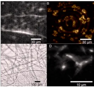
We have presented a toolkit that should greatly reduce the time that researchers need to develop a new microscopy solution by automatically handling most of the common boil-erplate tasks needed to set up a microscope, while is still giving the user the control over the instruments to perform any advanced microscopy technique. In order to show how efficient the program is at a number of common microscopy tasks, we have shown the results of image acquisition with
differing modularity in Fig. 5 with the corresponding
figure captions showing the equipment profiles. These figures show that the program can be used for bright field, stage scanning, beam scanning, and many other forms of microscopy with high performance. The program is open source and can be freely downloaded from http:// labviewmicroman.sourceforge.net/.
ACKNOWLEDGMENTS
This project has been funded by a starting investigator grant from the European Research Council.
1RCubed Software Consulting at具http://www.rcubedsw.com/典.
2HCIMAGE, Hamamatsu Software at 具http://sales.hamamatsu.com/
index.php?id⫽13224248典.
3Bruxton-SIDX at具http://www.bruxton.com/sidx/典. 4
DIGITAL OPTICSat具http://www.digitaloptics.net/典. 5
CAMACQJat具http://www.mbl.edu/research/labs/adlc/camacqj/典. 6A. Straw and M. Dickinson,Source Code Biol. Med.4, 5共2009兲. 7T. Pologruto, B. Sabatini, and K. Svoboda,Biomed. Eng. Online2, 13
共2003兲.
8N. Stuurman, N. Amodaj, and R. Vale, Microscopy Today15, 42共2007兲. 9METAMORPH, Life Science Research Imaging Systems, Bioanalytical
Software at 具http://www.moleculardevices.com/pages/software/ metamorph.html典.
10
NIS-ELEMENTSat具http://www.nis-elements.com/典. 11Olympus
MICROSUITE at http://www.leedsmicro.com/
oly_microsuite_basic.asp. 12
MICROSCOPE software, Leica Microsystems at 具 http://www.leica-microsystems.com/products/microscope-software/典.
13Media Cybernetics-Image Processing Software | Image Deconvolution |
Image Analysis at具http://www.mediacy.com/典.
14Imaging Workbench Home at具http://www.imagingworkbench.com/典. 15Home-Scilab WebSite at具http://www.scilab.org/典.
16WaveMetrics-scientific graphing, data analysis, curve fitting, and image
processing software at具http://www.wavemetrics.com/典. 17
PYTHON Programming Language—Official Website at 具http://
www.python.org/典.
18E. Jones, T. Oliphant, P. Petersonet al., SciPy: Open Source Scientific
Tools for Python, 2001,具http://www.scipy.org典.
19W. S. Rasband, ImageJ, U.S. National Institutes of Health, Bethesda,
Maryland, USA,http://rsb.info.nih.gov/ij/, 1997–2009. FIG. 5.共Color online兲 共a兲An image of collagen fibers acquired using
mul-tifocal, multiphoton microscopy under stochastic scanning. The image was produced by scanning 100 laser foci with galvos driven by a National In-struments DAQ controlled with the internal AutoMicromanager function generator, and images were acquired with a Cascade共Photometrics兲camera. 共b兲Quantum dot crystals illuminated by a two photon microscope, with the laser moving in a circular motion. Image was integrated on the Cascade camera, with the spinning laser beam motivated by a custom device created in the laboratory. The quantum dots were extremely bright and the toolkit acquired this series at 100 frames/s.共c兲A brightfield montage of cotton fibers. Image was captured with Cascade camera and an automated PI stage. The image is a composite image from 800 separate images, stitched to-gether. The images were generated by the stack and montage module in the Record and Save tools GUI control.共d兲Ridges in quantum dot crystals. Optical slices were acquired by a line scanner of a two photon generating laser spot combined with automated stage motion. The line scanner was created using a galvo mirror, and the stage was stepped perpendicularly with a PI stage. Galvo control of the laser spot is generated by aLABVIEWscript, while all the microscopy tasks were handled by AutoMicromanager.