TESTING OF PROTECTIVE STRUCTURES OF OPERATORS
IN AN OVERTURNING INCIDENT
PERSU C.1), MATACHE M.1), CUJBESCU D.1), VOICEA I.1), VLĂDUȚV.1), DUMITRU I.2), UNGUREANU N.2), BORUZ S.3), MIRCEA C.1) 1)INMA Bucharest / Romania;2)University POLITEHNICA Bucharest; 3)University of Craiova / Romania
E-mail:[email protected]
Keywords: protective structure, tractor, ROPS
ABSTRACT
In farms, overturning / rolling over of tractors is the main cause of accidents with serious consequences. In view of reducing the risk of injury for the operator of mobile machinery in case of rollover / roll the testing of the operator protective structure is required.The paper presents the testing procedure and the results obtained from the static tests of the operator protective structures (ROPS- Roll over protection structure).
INTRODUCTION
Protective structures is an essential element of mobile /self-propelled equipment because on their strength depends the safety and health of operators driving these equipment. Major risks may occur in transport on public roads (overturning, collision, etc.), when performing various operations in construction (accidental bumps, overturning, etc.) or when working in rugged forest areas (overturning, crash or accidental bumps, etc.). Appropriate testing of protective structures is an essential element in order to eliminate the risks of injury and increase operator safety in case of rollover / overturn.[1, 3, 4]
All mobile machinery have the risk of rolling during operation, depending on machinery characteristics, environment and soil to be worked. Hence, the need to protect the operator from the risk of being injured or being deady injured in a rollover is the most important factor in the design and development of self-propelled mobile machinery. For this purpose, worldwide were established norms and standards on the safety of the operators, to which the manufacturers of operator protective structures for this type of equipment must comply.[2, 6]
MATERIAL AND METHOD
The cabin is designed to ensure safe and comfort conditions for the driver that works on a tractor for forest exploitation. This complies with the provisions of Directive 80/720/EEC regarding the operating space, means of access to the driving position, doors and windows. [1 5]
Specifications of the tractor for which tests have been carried out:
-the protective structure on which research were made was designed and developed to equip it on a range of tractors with a maximum weight of 7500 kg, thus, was counted a mass of the unladen tractor, with the protective device mounted, 7500 kg without a driver;
- tire size:
front 18,4/15 - 26; rear 18,4/15 - 26; Specifications for the protective structure:
welding on one sole made of steel with thickness of 10 mm. In their middle are found two pillars of consolidation, made of the same profile Φ48x5 mm, having supportive role for the doors. The two side walls are reinforced transversally through five beams made of Φ48x5 mm pipe, forming a parallelepiped structure. The roof is made of steel sheet with thickness of 3 mm S235 (OL 37). Its attachment to the frame is also made by welding.
The cabin has two doors, one on each side, the right side door having the role of emergency exits. The doors consist of door frame which is made of T40x40x4 mm profile, door panel made of sheet steel with thickness of 2 mm and door glass.
At the bottom is provided a floor made of sheet steel. On the floor is mounted via a support the driver's seat.
Sizes (according to measurements made after determining the seat reference point):
- Height of roof frames above the seat reference point: 875 mm; - Height of frames above the leg support of the chair: 1399 mm;
- Inner width of the protective structure at 900 mm above the seat reference point 1016 mm;
- Inner width of the protective structure at a point situated above the seat at the steering wheel center of 1008 mm;
- Distance from the steering wheel center to the right side of the protective structure 505 mm;
- Distance from the steering wheel center to the left side of the protective structure 519 mm;
- Minimum distance from the steering wheel rim to the protective structure 55 mm; - Door width: - at the top 685 mm;
- in the middle 685 mm; - at the bottom 450 mm; - Door height above the platforms 1385 mm;
- Door height above the heighest step 1530 mm - Door height above the lowest step 1781 mm
- The distance measured horizontally behind the protective structure to 900 mm above the seat reference point: 450 mm;
- Characteristics of materials, quality of materials and reference standards (set by the manufacturer):
1. main frame: OLT 35 Tv Φ48x6 mm; 2. mounting points
3. carcass: OL 37 Tb 3 mm 4. roof: OL 37 Tb 3 mm
Fig.1- Mounting performed on "Hydropulse" facility for applying front longitudinal loadings
In compression tests in the front, the beam was placed on the most frontal top beam of the protective structure (Fig. 2).
Fig.2- Mounting performed on "Hydropulse" facility in case of frontal crushing
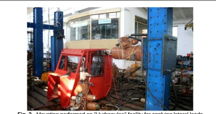
Fig. 3- Mounting performed on "Hydropulse" facility for applying lateral loads
When trying to compression in the rear side, the beam was placed on the most back upper beam of the protective structure. (Fig. 4).
Table 1
Type of test
Testing parameters
Name M.U. Minimum values calculated
according to D 79/622/EEC
Horizontally Longitudinal load from front energy J 10500
Lateral load energy J 13125
Vertically Front crushing force KN 2 x 75.0
Rear crushing force kN 2 x 75.0
In order to achieve the research conducted at the headquarters of INMA Bucharest - Department of Tests was used the following research infrastructure [4, 5]:
Testing facility under simulated and accelerated regime type Hydropulse, which is provided with the following equipment:
- Traction dynamometer, load cell in the composition of the measurement chain of the force within the Hydropulse facility (10-100 KN), type FC-10, series 8610, with measurement uncertainty of 0,89%.
- Traction dynamometer, load cell in the composition of the measurement chain of the force within the Hydropulse facility (10-100 KN), type FC-10, series 89421, with measurement uncertainty of 0,89%.
- Traction dynamometer, load cell in the composition of the measurement chain of the force within the Hydropulse facility (25-250 KN), type FC-10, series LMF 6619, with measurement uncertainty of 0,71%.
- System for displacement measurement with inductive transducer in the range of 0-500 mm, resolution 0.1 mm, manufacturer Hottinger, WA0-500 type, series 0521100400, with measurement uncertainty of 0.010 mm.
- System for displacement measurement with inductive transducer in the range of 0-500 mm, resolution 0.1 mm, manufacturer Hottinger, WA0-500 type, series 062510585, with measurement uncertainty of 0.010 mm.
- Pentium computer equipped with DAP 5200 E acquisition board - Microstar Laboratories.
- Optical rapporteur type U4 - 165 with 4 graded sectors, 4-90°, division 1', measurement uncertainty 2'00.
- Digital calliper 0 ÷ 150 mm SR 44 Series, measurement uncertainty 0.07 mm.
- Stanley measuring roulette, L = 8 m, series 2, measurement uncertainty 0.5 mm + 10-4L [4].
RESULTS AND DISCUSSIONS
Load tests were carried out in the front left and the lateral left (rear view). The reference mass used in calculating energy input and crushing forces was of 7500 kg.
Testing parameters and their values are shown in Table 1 and were set according to the reference mass of the forestry tractor and to the current regulations.
F - force;
∆ - deformation;
U - energy;
Permanent deformations obtained from the research and the absorbed energy obtained while perfoming the tests.
Loads applied frontally and laterally: - front - 11.52 kJ;
- rear 158.43 kN; - front 158.6 kN;
Final permanent deformation measured after the test: In the back: towards rear: left: 53 mm;
right: 42 mm; In the front: towards rear: left: 59 mm
right: 55 mm;
Laterally: front: 30 mm;
rear: 7 mm;
In the upper part: top-down: front: 3 mm; rear: 6 mm;
Fig.5– Energy absorbed during frontal loading - 11.52 kJ
CONCLUSIONS
In order to increase the safety of operator of mobile technical equipment destined for forestry exploitation, it is necessary and indispensable to conduct research on the strength of operator protective structure of such equipment.
Tractor cab subjected to research loads is designed to protect the driver and his companions of those hazards that may occur in overturning of the tractor or to mitigate their effect, in case of normal use.
Values of loads to which the protective structure was subjected were determined based on the documentation from the manufacturer.
Tests were carried out on testing facility type Hydropulse and aimed to verify the capability to take energy and forces applied to the cabin for the calculated values corresponding to a reference mass of the tractor of 7500 kg.
After the tests, the cabin showed no visible cracks or tears and during tests no part of it has entered the area of clearance.
BIBLIOGRAPHY
1. Persu C., Matache M, Vlăduţ V., Biriş S., Cujbescu D., Paraschiv G., Voicea I.,
Ivancu B, Ivan Gh. - Checking the mechanical resistance of an operator protection
structures, Proceedings of the 42 International Symposium on Agricultural Engineering "Actual Tasks on Agricultural Engineering", ISSN 1848-4425, 2015, Opatija – Croaţia
2. Găgeanu P., Pirnă I., Mihai M., Ganga M, Matache M. (2008) - Increasing of the
operators safety level of auto-propelled machines by dynamic testing of their protection structures, Scientific Papers (INMATEH), vol. 24 (1), pg. 234-238;
3. Matache M., Cârdei P., Vlăduţ V., Voicu Gh. - Researches regarding experimental
validation of structural analysis performed on resistance structures of agricultural machinery, Proceedings of the 42 International Symposium On Agricultural Engineering "Actual Tasks on Agricultural Engineering", pag. 149160, 2014, ISSN 1333-2651, Opatija - Croaţia
4. Vlăduţ V., Găgeanu P., Mihai M., Bungescu S., Lazăr Savin, 2007 - Using static and
dynamic method for the testing of the cabins and protection devices of the agricultural and forestry tractors on the wheels, Tractors and Power Machines 2, vol. 12, pg. 79-90, Novi Sad – Serbia
5. Directive 2009/75/EC of the European Parliament and of the Council of 13 July 2009
on roll-over protection structures of wheeled agricultural or forestry tractors (static testing).
6. Krishna N., 2001 -Modeling of rollover protective structure and falling object protective