345
CAD-CAE METHOD FOR STRUCTURAL ANALYSIS OF THE WELDED
FRAME WITHIN THE COMPONENT OF A SEED DRILL USED FOR
DIRECTLY SOWING STRAW CEREALS
EUGEN MARIN1, MARINELA MATEESCU1, DRAGOȘ MANEA1
1/National Institute of Research-Development for Machines and Installations Designed to Agriculture and Food Industry – INMA Bucharest, Romania
Keywords: disc knife, roots cutting, CAD designing, FEA structural analysis
ABSTRACT
This paper presents a Computer Assisted Design (CAD) method combined with computer-aided engineering (CAE) used in the analysis of choosing the constructive variant of the welded frame from within the component of a seed drill used for directly sowing straw cereals, so that the ratio between the consumption of material for the construction structure per unit of safety coefficient to be minimal and the carrying capacity to be maximal. For this purpose 3D modeling with SolidWorks software has effectively managed three dimensional configurations of the welded frame using Design Table. The three configurations were subjected to structural analysis (the von Mises equivalent of the tension field distribution, the relative displacement of field distribution and the safety coefficient). Based on the resulting data, the mass / resistance ratios for the three configurations analyzed were determined. The comparison of these indicators led to the choice of the optimal constructive variant in the most efficient way. The presented method contributes to reducing the design validation time by eliminating physical performance and testing.
INTRODUCTION
Optimal design of assemblies, subassemblies and components of mechanical engineering equipment are activities that are currently taking place in the work of advanced firms [4].
Designing of an optimal product or optimally improving existing products requires complex work tools that are now integrated into CAD / CAE complex programs [1].
Computer-aided design (CAD) defines the use of computer systems for the purpose of creating, modifying, analyzing and optimizing a design [6].
Computer-aided engineering (CAE) or Computer Assisted Engineering is the comprehensive definition of computer programs that aim at engineering analysis activities, including FEA, Fluid Dynamics (CFD), Multi-Body Dynamics the study of the dynamic behavior of rigid or flexible interconnected bodies, each of which can undergo large translation and rotation movements (MBD) and optimization [7].
For example, there are research done to use computer-aided engineering (CAE) in developing a systematic procedure that predicts the dynamic behaviors of an entire machine tool structure [5].
Another example of using Computer Assisted Engineering (CAE) is in the analysis of buckling-sensitive structures to give the potential user the possibility to investigate the effects of different types of critical load conditions on carcasses, as the components of a machine [2].
346
This paper presents a new method which contributes to reduce the design validation time.
MATERIAL AND METHOD
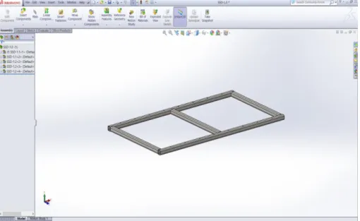
The theoretical researches were carried out by 3D parametric modeling by the help of the SolidWorks 2013 program [8] of the welded frame of the seed drill (fig. 1) used for directly sowing straw cereals (for example: wheat, rape, medicinal herbs, peas, mustard+phacelia, trefoil+grass etc.),especially in light and medium soils, on plains or slope field up to 6°, within ADER 16.3 .1 contract, concluded between INMA Bucharest and Ministry of Agriculture and Rural Development, the title project: Researches on influence of applying new conservative systems and technologies of mechanized agricultural works for fighting against drought effects, preserve soil fertility and qualitatively and quantitatively increase the production of the main plant species cultivate [9].
Fig. 1. Welded frame within the seed drill used fordirectly sowing straw cereals
In situation when we had managed a number of three configurations, SolidWorks for each landmark of the welded frame, it was helpful with Design Table having the icon that suggests an Excel file (Figure 2).
347
By using Microsoft Excel, it was easy to manage the configurations and after closing the application, the system switched to SolidWorks where we went through each operation to see if we were the way we wanted it to.
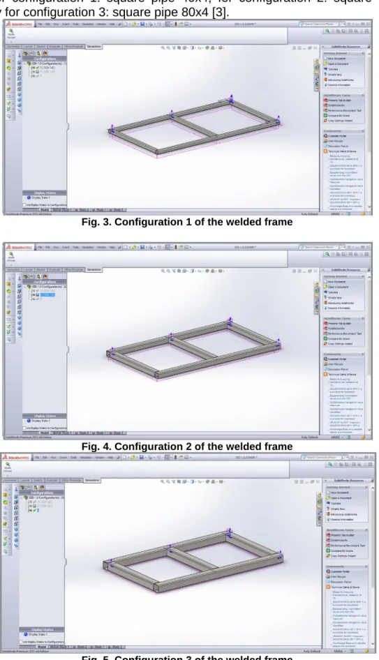
Figures 3, 4 and 5 show welding frame configurations 1, 2 and 3 when the base profile is for configuration 1: square pipe 40x4, for configuration 2: square pipe 60x4, respectively for configuration 3: square pipe 80x4 [3].
Fig. 3. Configuration 1 of the welded frame
Fig. 4. Configuration 2 of the welded frame
348
After the welding frame configuration was completed, the structural analysis of the Solid Works SIMULATION 2013 structural simulation application has been done, which implied the import of the geometry of the model with the computer-aided engineering, defined the material of each component definition, definition of appropriate mesh restrictions, analysis calculation to determine stresses, displacements under the effect of an applied load, safety coefficient and result visualization.
The structural analysis required the following operations:
- selecting the static option as a solid type for the discretization type and the FFEPlus solver;
- selecting materials and assigning these properties automatically to each component reference;
- applying the appropriate task:
- in accordance with the actual operation (operation) of the welded frame, the simulation scenario was adapted accordingly;
- the load was applied at the points corresponding to the assembly of the soil and seed drills,
- using the meshing procedure to break the pattern into discrete elements:
- in general, a finite element model is defined by a network, which is completely accomplished, from a geometric arrangement of elements and nodes;
- nodes are points in which characteristics are calculated, such as displacements,
- run the analysis study to calculate the voltage, safety factor and displacement, which is based on geometry, material, load, restriction conditions and discretization type.
The three configurations were subjected to structural analysis (the von Mises equivalent of the tension field distribution, the relative displacement of field distribution and the safety coefficient).
After running the analysis studies, the results is visualised for comparison.
The comparison of these indicators led to the choice of the optimal constructive variant in the most efficient way.
RESULTS AND DISCUSSIONS
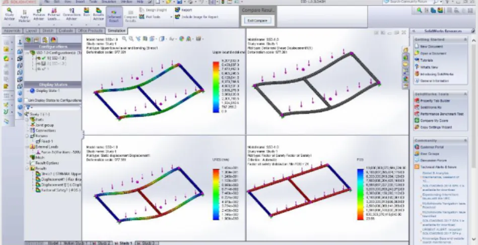
In Figures 6, 7 and 8 there are presented sequences from the comparison of the analysis studies and results for the three welded frame configurations that appear on the screen in the form of the von Mises tenssion distribution, the displacement distribution, the shape of the strain and the safety coefficient.
Fig. 6.Sequence during comparison of analysis and results analysis for configuration 1
349
maximum von Mises pressure of 9.20MPa is in the side nodes, the maximum displacement of 0, 1494 mm is in the center and the minimum safety factor of 23.96 is in the center bar and the front / back.
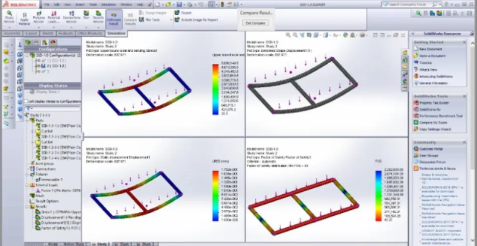
Fig. 7. Sequence during comparison of analysis study and results for configuration 2
Analyzing the sequence in Figure 7 for the welded frame configuration 2 where the maps of the von Mises pressure distribution, motion and the safety factor are shown, the maximum von Mises pressure of 5.09 MPa is in the central nodes, the maximum displacement of 0.1782 mm is in the center and the minimum safety factor of 47.27 is in the center bar and the front / back.
Fig. 8. Sequence from comparison analysis and results study for configuration 3
Analyzing the sequence in figure 8 for the welded frame configuration 3 where the maps of the von Mises pressure distribution, motion and safety factor are shown, the maximum von Mises pressure of 1.7 MPa is in the side nodes, the maximum displacement of 0.1475 mm is at the center and the minimum safety factor of 126.63 is in the center bar and the front / back.
The results of the structural analysis for the three constructive configurations of the welded frame in the composition of a straw grain seed drill are shown in Table 1.
350
Table with synthesis of resultant structural configurations considered
Table 1
Name Measure
unit
Values
Config. 1 Config. 2 Config. 3
Distribution of the pressure field equivalent von Mises
N/mm2
(MPa) 9.20 5.09 1.70
Distribution of the relative
displacement field, mm mm 0.1494 0.1782 0.1475
Safety factor - 23.96 43.27 126.63
Total weight kg 21.899 35.003 48.107
Material consumption per unit of
safety coefficient - 0.91 0.80 0.37
CONCLUSIONS
- The high value of the safety coefficient, relative to the usual values, shows that there is an important optimization potential for the welded frame.
- The material consumption indicator unit per unit of safety coefficient unit proposed to analyze the choice of a welded configuration contributes to reducing design validation time.
BIBLIOGRAPHY
1. T.G. Alexandru, C. Pupăză, 2017, Eco-design of heat sinks based on CAD/CAE
techniques, Proceedings in Manufacturing Systems, Volume 12, Issue 1, pg. 9‒16, ISSN
2067-9238
2. J. Arbocz, J.M.A.M Hol, 1993, Shell stability analysis in a computer aided engineering
(CAE) environment, Conference: 34. American Institute of Aeronautics and Astronautics/American Society of Mechanical Engineers (AIAA/ASME) adaptive structures conference, La Jolla, CA (United States) https://doi.org/10.2514/6.1993-1333
3. L. Dong-Chan, H. Chang-Soo, 2009, CAE (computer aided engineering) driven
durability model verification for the automotive structure development, Finite Elements in Analysis and Design, Volume 45, Issue 5, Pages 324-332
4. L. Tudose, D. Pop, S. Haragâş, G. Nistor, D. Jucan, M. Pustan, 2006, Optimal
designing of complex systems/Proiectarea optimală a sistemelor complexe, 318, Mediamira Publishing House/Editura Mediamira, ISBN 973-713-076-6, Cluj-Napoca
5. G.P. Zhang, Y.M. Huang, W.H. Shi, W.P. Fu, 2003, Predicting dynamic behaviors of a
whole machine tool structure based on computer-aided engineering, International Journal of Machine Tools and Manufacture, Volume 43, Issue 7, Pages 699-706
6. *** https://en.wikipedia.org/wiki/Computer-aided_design 7. *** https://en.wikipedia.org/wiki/Computer-aided_engineering
8. *** http://www.solidworks.com/sw/products/simulation/simulation.htm
9. *** http://www.madr.ro/cercetare-inovare/ader-2015-2018/ader-16/204-ader-16-3-1.html