Performance Analysis Of IPMSM Drive Using Fuzzy Logic Controller
Based Loss Minimization Algorithm (LMA)
P. Sandeep, G. Venkata Sagar, Subbiramireddy
M.Tech Scholar, Associate Professr,K.O.R.M College Of Engineering, Kadapa
Abstract: This project presents an online loss-minimization algorithm (LMA) for a fuzzy-logic-controller (FLC)-based interior permanent-magnet synchronous-motor (IPMSM) drive to yield high efficiency and high dynamic performance over a wide speed range. LMA is developed based on the motor model. In order to minimize the controllable electrical losses of the motor and thereby maximize the operating efficiency, the d-axis armature current is controlled optimally according to the operating speed and load conditions. For vector-control purpose, FLC is used as a speed controller, which enables the utilization of the reluctance torque to achieve high dynamic performance as well as to operate the motor over a wide speed range. In order to test the performance of the proposed drive in real time, the complete drive is experimentally implemented using DSP board DS1104 for a prototype laboratory 5-hp motor. The performance of the proposed loss-minimization-based FLC for IPMSM drive is tested in both simulation and experiment at different operating conditions. A performance comparison of the drive with and without the proposed LMA-based FLC is also provided. It is found from the results that the proposed LMA and FLC-based drive demonstrates higher efficiency and better dynamic responses over FLC-based IPMSM drive without LMA. In this project, an online LMA-based speed-control scheme of IPMSM drive incorporating an FLC has been presented. The LMA was developed based on the motor model.
NOMENCLATURE:
id, iq d–q-axis stator currents in synchronous rotating frame.
vd, vq d–q-axis stator voltages in synchronous rotating frame.
Ld, Lq d–q-axis self-inductances.
P Number of pole pairs.
Ψ Magnetic-flux linkage.
ωr Actual electrical rotor speed.
V`a Maximum terminal voltage ignoring stator resistance.
e,Δe Speed error and change of speed error.
Ra, Rc Stator copper-loss and iron-loss resistances.
iod d-axis demagnetizing armature current.
ioq q-axis torque-generating armature current.
icd, icq d–q-axis core-loss armature currents.
PCu, PFe Copper loss and iron loss of interior permanent magnet synchronous motor (IPMSM). PE Total electrical loss of IPMSM PE = PCu + PFe.
PM Mechanical loss of IPMSM.
PL Total loss of IPMSM PL = PE + PM.
Te, TM Developed torque and frictional torque.
J Rotor inertia constant.
Bm Friction damping coefficient.
INTRODUCTION:
been widely utilized in industries, but they exhibit poor efficiency due to inherent rotor copper loss. An interior permanent-magnet synchronous motor (IPMSM) can be a very good replacement in this case for variable-speed drive systems due to its high torque–current ratio, large power–weight ratio, high efficiency, high power factor, low noise, and robustness. The motor losses consist of mechanical loss, copper loss, and iron loss. Copper and iron losses are controllable, but the mechanical loss is speed dependent and not controllable. Copper loss can be minimized by maximum torque-per-ampere current-control (MTPA) method. The iron loss can be minimized by flux weakening control, in which the d-axis current is controlled in order to reduce the air-gap flux by the demagnetizing effects due to the d-axis armature reaction, because iron loss is roughly proportional to the square of flux density.
Despite the many advantageous features of an IPMSM, the precious speed control of an IPMSM is difficult due to nonlinear coupling among its winding currents and the rotor speed, as well as the nonlinearity present in the electromagnetic developed torque because of magnetic saturation of the rotor core. The important characteristics of high performance drive systems are fast and precise speed response, quick recovery of speed from any disturbances, parameter insensitivity, and robustness in the variable-speed domain. Over the years, control issues have been handled by the conventional proportional–integral (PI) controller, proportional–
integral–derivative (PID) controller, model-reference adaptive controller, sliding-mode controller, variable-structure controller, etc. The designs of these controllers depend on exact machine model and accurate model parameters. However, the difficulties of obtaining the exact d–q-axis reactance parameters of the IPMSM lead to cumbersome design approach for these controllers. Moreover, the fixed-gain PI and PID controllers are very sensitive to disturbance. On the other hand, the designs of intelligent controllers, such as fuzzy logic, neural network, neurofuzzy controllers, etc., do not need exact mathematical model of the system. Simplicity and less intensive mathematical design requirements are the main features of intelligent controllers, which are suitable to deal with nonlinearities and uncertainties of electric motors. Therefore, the intelligent controllers demand particular attention for high-performance nonlinear IPMSM drive systems. Among the various intelligent controllers, fuzzy-logic controller (FLC) is the simplest and better than others in terms of quick response time, insensitivity to parameter and load
variation, etc. Thus, in this paper an FLC is utilized as a speed controller for vector control of the IPMSM. The conventional FLC always emphasizes on the dynamic performance of the drive system. However, efficiency, which is an important factor for industrial drives, is often ignored by the researchers. Therefore, in this work, the loss-minimization algorithm (LMA) is integrated with the FLC so that high dynamic performance can be achieved while maintaining high efficiency. The LMA is developed based on the motor model which provides the optimum values of id and iq. The FLC is designed based on MTPA operation below the rated speed and flux-weakening operation above the rated speed in order to extend the operating region.
In order to test the performance of the proposed drive in real time, the complete drive is experimentally implemented using DSP board DS1104 for a prototype laboratory 5-hp motor. The performance of the proposed LMA-based FLC for IPMSM drive is tested in both simulation and experiment at different operating conditions. A performance comparison of the drive with and without the proposed LMA-based FLC is also provided. The proposed LMA and FLC-based drive demonstrates higher efficiency and better dynamic responses over FLC-based IPMSM drive without LMA.
FUZZY LOGIC CONTROLLER
In recent years, the number and variety of applications of fuzzy logic have increased significantly. The applications range from consumer products such as cameras, camcorders, washing machines, and microwave ovens to industrial process control, medical instrumentation, decision-support systems, and portfolio selection.
To understand why use of fuzzy logic has grown, you must first understand what is meant by fuzzy logic.
In fuzzy Logic Toolbox software, fuzzy logic should be interpreted as FL, that is, fuzzy logic in its wide sense. The basic ideas underlying FL are explained very clearly and insightfully in Foundations of Fuzzy Logic. What might be added is that the basic concept underlying FL is that of a linguistic variable, that is, a variable whose values are words rather than numbers. In effect, much of FL may be viewed as a methodology for computing with words rather than numbers. Although words are inherently less precise than numbers, their use is closer to human intuition. Furthermore, computing with words exploits the tolerance for imprecision and thereby lowers the cost of solution.
Another basic concept in FL, which plays a central role in most of its applications, is that of a fuzzy if-then rule or, simply, fuzzy rule. Although rule-based systems have a long history of use in Artificial Intelligence (AI), what is missing in such systems is a mechanism for dealing with fuzzy consequents and fuzzy antecedents. In fuzzy logic, this mechanism is provided by the calculus of fuzzy rules. The calculus of fuzzy rules serves as a basis for what might be called the Fuzzy Dependency and Command Language (FDCL).
Although FDCL is not used explicitly in the toolbox, it is effectively one of its principal constituents. In most of the applications of fuzzy logic, a fuzzy logic solution is, in reality, a translation of a human solution into FDCL.
A trend that is growing in visibility relates to the use of fuzzy logic in combination with neuron computing and genetic algorithms. More generally, fuzzy logic, neuron computing, and genetic algorithms may be viewed as the principal constituents of what might be called soft computing. Unlike the traditional, hard computing, soft computing accommodates the imprecision of the real world.
The guiding principle of soft computing is: Exploit the tolerance for imprecision, uncertainty, and partial truth to achieve tractability, robustness, and low solution cost. In the future, soft computing could play an increasingly important role in the conception and design of systems whose MIQ (Machine IQ) is much higher than that of systems designed by conventional methods.
Among various combinations of methodologies in soft computing, the one that has highest visibility at this juncture is that of fuzzy logic and neuro computing, leading to neuro-fuzzy
systems. Within fuzzy logic, such systems play a particularly important role in the induction of rules from observations. An effective method developed by Dr. Roger Jang for this purpose is called ANFIS (Adaptive Neuro-Fuzzy Inference System). This method is an important component of the toolbox.
The fuzzy logic toolbox is highly impressive in all respects. It makes fuzzy logic an effective tool for the conception and design of intelligent systems. The fuzzy logic toolbox is easy to master and convenient to use. And last, but not least important, it provides a reader friendly and up-to-date introduction to methodology of fuzzy logic and its wide ranging applications.
PROPOSED IPMSM DRIVE SYSTEM DESIGN
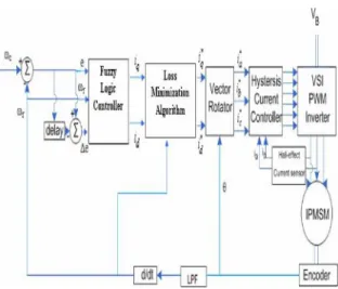
Fig. 1. Block diagram of the proposed LMA and FLC-based IPMSM drive.
In order to achieve both high efficiency and high dynamic performance of IPMSM, a closed-loop vector-control scheme incorporating the FLC and LMA is used. The complete block diagram of the drive system is shown in Fig. 1. The details of the FLC and LMA algorithms are discussed in the following sections.
A. FLC
For the proposed FLC, the input variables are actual speed (ωr), speed error (e), and change of speed error
(Δe), and the output variables are apparent d- and q-axes currents id and iq, respectively. The membership function of iq (one output of FLC) is designed in such a way that the motor can generate the necessary torque to follow the command speed as quickly as possible. This can be done based on the knowledge of operation on fuzzy logic and motor control. Thus, the main challenge is to design the membership functions of id (another output of the FLC), which is necessary for flux control. These membership functions are designed based on MTPA operation below the rated speed and flux-weakening operation above the rated speed.
Below the rated speed, the simplified MTPA relation can be written as
id =−((Lq− Ld)/ψ)i2q (1)
where ψ is the magnetic-flux linkage. This equation is utilized as a basis to design the membership functions of id below the rated speed. The scaling factor for iq(kq) is selected by trial and error in such a way that the motor generates rated torque at rated condition. The scaling factor for id(kd) will be equal to ((Lq − Ld)/ψ)k2q below the rated speed. The
scaling factors (ke, kω) at the input side of the FLC depend on the rated speed of the motor so that their normalized values lie within the limit ±2. The other scaling factor (kΔe) at the input side is chosen by
trial-and-error method.
Above the rated speed, the magnetic flux must be weakened by the armature reaction of id in order to maintain the stator voltage constant at its maximum value. Thus, the field weakening not only extends the operating limits of IPMSM drive but also relieves the controller from saturation that occurs at high speeds. The simplified flux-weakening relation can be obtained as
= − + ` (2)
where V`a is the maximum terminal voltage neglecting stator resistance in steady state and P is the number of pole pairs. Therefore, at rated speed, V`a can be written as
(V’a)2 = P2ωr2(rated)ψ2. (3)
From (2) and (3), one can obtain
= − + ( ) (4)
= − +
( )
= −1 +
( ) (5)
whereωr(normalized)=ωr/ωr(rated).
Therefore, the scaling factor for id is kd = ψ/Ld for the field-weakening region. Equation (5) is utilized as a basis to design the membership functions of id above the rated speed. The membership functions for various input and output variables used for the proposed FLC are shown in Fig. 2. Once the membership functions are selected, the next step is to choose the fuzzy rules based on the control strategies mentioned earlier. The fuzzy rules used for the proposed FLC are as follows.
1) If e is PH (positive high), then iq is PH (positive high), and id is PH (positive high).
2) If e is PL (positive low), then iq is PL (positive low) and id is PL (positive low).
3) If e is NH (negative high), then iq is NH (negative high) and id is NH (negative high).
4) If e is NL , then iq is NL (negative low) and id is NL (negative low).
5) If e is ZE (zero) andωris WR, then iq is NC and id is NC (not change).
6) If ωr is PAR (positive above rated ) or NAR (negative above rated), then iq is NL (negative low) and id is AR (above rated).
7) If eis ZE (zero) and Δe is PI (positive), then iq is PH (positive high) and id is PH (positive high).
Fig. 2. Membership functions of the proposed FLC: (a) e. (b)ωr. (c) Δe. (d) iq. (e) id.
B. LMA
Based on Fig. 3, the mathematical equations of the equivalent d–q axis model of IPMSM in the rotor reference frame are given as
Fig. 3. d–q-axis models of IPMSM incorporating iron loss: (a) d-axis. (b) q-axis.
= + 1 +
(6)
= 0 − 0 + 0
(7)
icd =− icq = (ωr(ψ+ iodLd))/Rc
(8)
iod =id–icd ioq = iq–icq (9)
voltages, iod and ioq are the d-axis demagnetizing and q-axis torque generating currents, icd and icq are d-axis and q-axis core-loss currents, Ra and Rc represent the stator copper-loss and iron-loss resistances, and Lq and Ld are q-axis and d-axis self-inductances, respectively; ρ = Lq/Ld. The developed torque can be expressed as
Te =P {ψioq+ (1− ρ)Ldiodioq} (10)
Based on (8) and (9), the losses can be expressed as
PCu=Ra (id 2
+ iq
2 )
(11)
PFe=Rc (icd2+ icq2)
(12)
PM=ωrTM
(13)
where TM is the frictional torque of the motor. The output power Pout and efficiency of the IPMSM driveηare expressed as
PE =PCu + PFe , PL = PM + PE (14)
Pout =ωrTe η = Pout/(Pout + PL) ×
100 (15)
Efficiency can be improved by minimizing the controllable electrical losses PE. In steady state, the loss-minimization condition can be derived by partially differentiating PE with respect to iod and equating to zero as
∂PE/∂iod= 0 assuming Te, andωras constants. (16)
As a result, the loss-minimization condition is given as
XY− Te2Z = 0
(17)
where X, Y, and Z are given by
MATLAB CASE STUDY AND SIMULATION RESULTS
Simulation diagram of PI with LMA
Simulation diagram of FUZZY with LMA
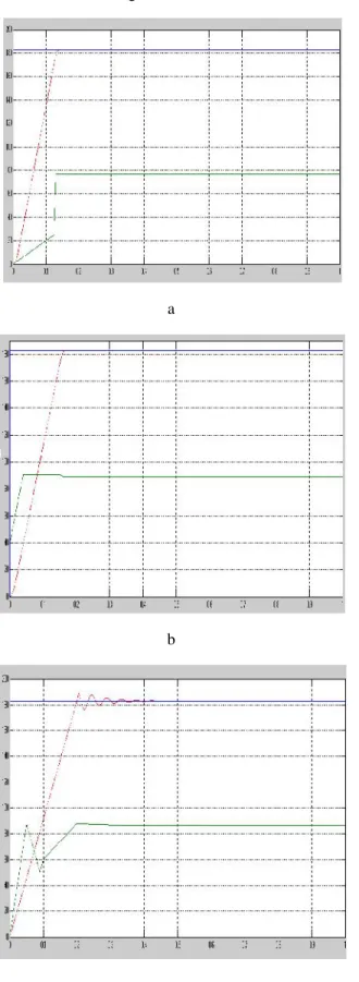
a
b
c
Fig. 5. Comparison of starting responses for the IPMSM drives at rated speed (183 rad/s) and 50% rated load (9.55 N · m): (a) FLC without LMA. (b) FLC with LMA. (c) Well-tuned PI with LMA.
a
CONCLUSION
In this paper, an online LMA-based speed-control scheme of IPMSM drive incorporating an FLC has been presented. The LMA was developed based on the motor model. The d-axis armature current was controlled optimally based on the developed LMA to minimize the controllable losses and hence maximized the operating efficiency. The FLC was used as a speed controller, and it helped to extend the operating speed limit of the motor. The LMA was incorporated with the FLC so that the motor can operate over wide speed range while maintaining high efficiency. It is true that some sacrifices were made for the MTPA-based FLC to integrate with the LMA in order to get the benefits of both algorithms. However, as the proposed IPMSM drive worked fine with stable responses both in simulation and real time, it proves that MTPA and LMA intersect with each other at some optimum operating point. Thus, it also justifies the stability of the proposed scheme. A performance comparison of the FLC-based IPMSM drive with and without LMA was also provided in the simulation. Simulation results demonstrated the higher efficiency and better dynamic response of the LMA-based drive as compared with that without LMA over a wide speed range. The complete drive was also experimentally implemented using DSP board DS1104. The experimental results also showed high efficiency and high dynamic performance of the proposed FLC and LMA-based IPMSM drive.
APPENDIX
183 V, Ia = 14.2 A, Lq = 6.42 mH, Ld = 5.06 mH, rated frequency = 87.5 Hz, rated speed = 183 rad/s, rated torque = 19.1 N · m, TM = 0.001 N · m, Prated = 5 hp, J = 0.0133 kg · m2, Bm = 0.001 N · m/rad/s, andψ= 0.24 Wb.
REFERENCES
[1] S. Yamamura, AC Motors for High-Performance Applications. New York: Marcel Dekker, 1986.
[2] G. R. Slemon, Electric Machines and Drives. Reading, MA: Addison- Wesley, 1992, pp. 503–551.
[3] A. Fransua and R. Magureanu, Electric Machines and Drive Systems. Bucharest, Hungary: Technical Press, 1984.
[4] R. D. Findlay, N. Stranges, and D. K. MacKay,
“Losses due to rotational flux in three phase induction motors,” IEEE Trans. Energy Convers., vol. 9, no. 3, pp. 543–549, Sep. 1994.
[5] S. Lim and K. Nam, “Loss-minimising control
scheme for induction motors,”Proc. Inst. Elect. Eng., vol. 151, no. 4, pp. 385–397, Jul. 2004.
[6] F. Abrahamsen, F. Blaabjerg, J. K. Pedersen, and
P. B. Thoegersen, “Efficiency-optimized control of medium-size induction motor drives,” IEEE Trans. Ind. Appl., vol. 37, no. 6, pp. 1761–1767, Nov./Dec. 2001.
[7] T. M. Jahns, G. B. Kliman, and T. W. Neumann,
“Interior permanent magnet synchronous motors for adjustable speed drives,” in Conf. Rec. IEEE-IAS Annu. Meeting, 1985, pp. 814–823.
[8] S. Morimoto, M. Sanada, and Y. Takeda, “Wide
speed operation of interior permanent magnet synchronous motors with high performance current
regulator,”IEEE Trans. Ind. Appl., vol. 30, no. 4, pp. 920–926, Jul./Aug. 1994.
[9] T. Sebastian and G. R. Slemon, “Operatinglimits of inverter driven permanent magnet synchronous
motor drives,” IEEE Trans. Ind. Appl., vol. IA-23, no. 2, pp. 327–333, Mar./Apr. 1987.
[10] S. D. Wee, M. H. Shin, and D. S. Hyun, “Stator -flux-oriented control of induction motor considering iron loss,”IEEE Trans. Ind. Electron., vol. 48, no. 3, pp. 602–608, Jun. 2001.
[11] T. M. Jahns, “Flux-weakening regime operation of an interior permanent magnet synchronous motor
drive,”IEEE Trans. Ind. Appl., vol. IA-23, no. 4, pp. 681–689, Jul./Aug. 1987.
[12] S. Morimoto, M. Sanada, and Y. Takeda,
“Effects and compensation of magnetic saturation in
flux-weakening controlled permanent magnet
synchronous motor drives,” IEEE Trans. Ind. Appl., vol. 30, no. 6, pp. 1632–1637, Nov./Dec. 1994.
[13] C. Mademlis and V. G. Agelidis, “On
considering magnetic saturation with maximum torque to current control in interior permanent
magnet synchronous motor drives,” IEEE Trans. Energy Convers., vol. 16, no. 3, pp. 246–252, Sep. 2001.
[14] M. M. I. Chy and M. N. Uddin, “Development and implementation of a new adaptive intelligent
speed controller for IPMSM drive,”IEEE Trans. Ind. Appl., vol. 45, no. 3, pp. 1106–1115, May/Jun. 2009.
[15] D. F. Chen, T. H. Liu, and C. K. Hung,
“Nonlinear adaptive backstepping controller design
for a matrix-converter based PMSM control system,”
in Conf. Rec. IEEE-IAS Annu. Meeting, 2003, vol. 1, pp. 673–678.
[16] K. Hwakim and M. J. Youn, “A nonlinear speed
control for a PM synchronous motor using a simple
disturbance estimation technique,” IEEE Trans. Ind. Electron., vol. 49, no. 1, pp. 524–534, Jun. 2002.
[17] M. Krstic, I. Kaneelankopoilos, and P. Kokotovic, Nonlinear and Adaptive Control Design. New York: Wiley, 1995.
[18] M. Tursini, F. Parasiliti, and D. Zhang, “Real -time gain tuning of PI controllers for
high-performance PMSM drives,”IEEE Trans. Ind. Appl., vol. 38, no. 4, pp. 1018–1026, Jul./Aug. 2002.
[19] Z. Ibrahim and E. Levi, “A comparative analysis
of fuzzy logic and PI speed control in high performance AC drives using experimental approach,”IEEE Trans. Ind. Appl., vol. 38, no. 5, pp. 1210–1218, Sep./Oct. 2002.
[20] A. Rubaai, D. Rickattes, and M. D. Kankam,
“Development and implementation of an adaptive
fuzzy-neural network controller for brushless drives,”
IEEE Trans. Ind. Appl., vol. 38, no. 2, pp. 441–447, Mar./Apr. 2002.
Systems. Englewood Cliffs, NJ: Prentice-Hall, 1996, pp. 533–607.
[22] Y. Yi, D. M. Vilathgamuwa, and M. A. Rahman,
“Implementation of an artificial-neural-network based real-time adaptive controller for an interior
permanent magnet motor drive,” IEEE Trans. Ind. Appl., vol. 39, no. 1, pp. 96–104, Jan./Feb. 2003.
[23] M. A. Rahman, M. N. Uddin, and M. A. Abido,
“An artificial neural network for online tuning of a
genetic based PI controller for interior permanent
magnet synchronous motor drive,” Can. J. Elect. Comput. Eng., vol. 31, no. 3, pp. 159–165, Jul. 2006.
P. SANDEEP currently persuing his M.TECH in power electronics and electrical drives from K.O.R.M college of engineering, kadapa, Affiliated to JNTU, Anantapuramu. He has done his B.TECH degree from Annamacharya Institute of Technology and Science, Affiliated to JNTU Anantapuramu, Rajampet, kadapa district, India.
G. VENKATA SAGAR working as Associate professor in Department of Electrical and Electronics Engineering Branch from K.O.R.M college of Engineering, Kadapa, India, Affiliated to JNTU Anantapuramu with 5 years of experience in teaching and various fields.