Mitigation of Non Linear Induced Harmonics In Grid Using Droop
Controlled PV Based DG Shunt APF
U.V.S.R Harisha*1, G.V.Ram Mohan2
1PG Scholar, Department of EEE, Kakinada Institute of Engineering and Technology-II, Korangi, Andhra Pradesh, India.
2Assistant Professor, Department of EEE, Kakinada Institute of Engineering and Technology, Korangi, Andhra Pradesh,
India.
ABSTRACT
This paper exhibitions the network tied Solar Photovoltaic generator system providing to nonlinear loads based Shunt Active Power Filter for reactive power remuneration and symphonious moderation by hang control technique. Solar PV system is a promising wellspring of vitality with incredible enthusiasm for spotless and sustainable power sources. The rising number of power hardware based gear is bringing about quality issues of electric power supply. Both high power mechanical loads and residential loads cause numerous unsettling influences in the utility side, for example, music, awkwardness, lists, swells, glimmers and recurrence variety. Power quality issues may emerge in the system or might be made by the buyer itself. In this paper, the proposed controller using power references demonstrates some huge changes in principle and a basic control topology. The PV module is associated with the DC side of Shunt Active Filter through the DC-DC converter. Converter switch is controlled by Perturb and Observe (P&O) Maximum Power Point Tracking (MPPT) calculation and it dispenses with the disadvantage in the regular PV system. A copying utilizing MATLAB Simulink is displayed to approve the benefit of the proposed system.
Keywords: Photovoltaic, nonlinear loads, Shunt Active
Power Filter, reactive power remuneration
I. INTRODUCTION
The power request dependably surpasses the accessible power era in any creating nation. Henceforth, inexhaustible power producing systems, for example, PV and wind vitality transformation systems are utilized to supplement the non-renewable energy source based power era. However, due to the non-linearity of the load that is diode connect rectifier with RL-load, there is music in the load streams. Consequently, music diminishment and reactive power remuneration at the same time should be possible by utilizing a voltage source inverter associated in parallel with the system which goes about as a shunt APF for decreasing the mutilations delivered due to non-straight load in the load current. This active filter creates a repaying current which is of equivalent in greatness as consonant present
and inverse in stage with it to decrease the sounds show in the load current.APF is named arrangement, shunt or mix both arrangement and shunt however shunt APF is favored here as the guideline of the shunt APF is to deliver remunerating streams of equivalent in extent yet inverse in-stage to those music that are available due to non-direct loads. SAPF is a shut circle structure where non-direct loads go about as straight. It can repay reactive power and can likewise alleviate sounds and twists.
Fig.1 Principle of shunt APF
In Fig. 1. Air conditioning mains is associated with the non-direct load that is diode connect rectifier with RL-load where,
- Source current
- Load current delivered due to non-direct load –
Compensating current created by shunt APF to alleviate music
- Source inductance - Load inductance 1–Coupling inductance
Here, the shunt APF created remunerating streams of equivalent in size however inverse in-stage to those sounds that are available due to non-direct loads which brings about alleviation of music at load current. For the most part, the voltage source inverters (VSI) are utilized to change over the power of the PV system to infuse it to the conveyance system. In any case, here, the VSI go about as a multifunctional gadget which is utilized for vitality change and furthermore for music disposal and also reactive power pay at the same time. This control system joins P-Q arrangement as in shunt active power filter strategy. This control procedure is same as strategy utilized as a part of shunt filter to decrease sounds in the
Mitigation of Non Linear Induced Harmonics In Grid Using Droop
Controlled PV Based DG Shunt APF
U.V.S.R Harisha*1, G.V.Ram Mohan21PG Scholar, Department of EEE, Kakinada Institute of Engineering and Technology-II, Korangi, Andhra Pradesh, India.
2Assistant Professor, Department of EEE, Kakinada Institute of Engineering and Technology, Korangi, Andhra Pradesh,
India.
ABSTRACT
This paper exhibitions the network tied Solar Photovoltaic generator system providing to nonlinear loads based Shunt Active Power Filter for reactive power remuneration and symphonious moderation by hang control technique. Solar PV system is a promising wellspring of vitality with incredible enthusiasm for spotless and sustainable power sources. The rising number of power hardware based gear is bringing about quality issues of electric power supply. Both high power mechanical loads and residential loads cause numerous unsettling influences in the utility side, for example, music, awkwardness, lists, swells, glimmers and recurrence variety. Power quality issues may emerge in the system or might be made by the buyer itself. In this paper, the proposed controller using power references demonstrates some huge changes in principle and a basic control topology. The PV module is associated with the DC side of Shunt Active Filter through the DC-DC converter. Converter switch is controlled by Perturb and Observe (P&O) Maximum Power Point Tracking (MPPT) calculation and it dispenses with the disadvantage in the regular PV system. A copying utilizing MATLAB Simulink is displayed to approve the benefit of the proposed system.
Keywords: Photovoltaic, nonlinear loads, Shunt Active
Power Filter, reactive power remuneration
I. INTRODUCTION
The power request dependably surpasses the accessible power era in any creating nation. Henceforth, inexhaustible power producing systems, for example, PV and wind vitality transformation systems are utilized to supplement the non-renewable energy source based power era. However, due to the non-linearity of the load that is diode connect rectifier with RL-load, there is music in the load streams. Consequently, music diminishment and reactive power remuneration at the same time should be possible by utilizing a voltage source inverter associated in parallel with the system which goes about as a shunt APF for decreasing the mutilations delivered due to non-straight load in the load current. This active filter creates a repaying current which is of equivalent in greatness as consonant present
and inverse in stage with it to decrease the sounds show in the load current.APF is named arrangement, shunt or mix both arrangement and shunt however shunt APF is favored here as the guideline of the shunt APF is to deliver remunerating streams of equivalent in extent yet inverse in-stage to those music that are available due to non-direct loads. SAPF is a shut circle structure where non-direct loads go about as straight. It can repay reactive power and can likewise alleviate sounds and twists.
Fig.1 Principle of shunt APF
In Fig. 1. Air conditioning mains is associated with the non-direct load that is diode connect rectifier with RL-load where,
- Source current
- Load current delivered due to non-direct load –
Compensating current created by shunt APF to alleviate music
- Source inductance - Load inductance 1–Coupling inductance
www.ijseat.com
* Corresponding Author
Page 496
International Journal of Science Engineering and Advance
Technology, IJSEAT, Vol. 5, Issue 5
ISSN 2321-6905
May-2017
dispersion organize due to non-straight loads in the system.
This paper is composed as takes after Section II gives outline on PV cell, its fundamental hypothesis, associations demonstrating and impact of temperature and illumination on PV board. Area III depicted MPPT P and O calculation and its usage for most extreme power extraction from a PV system associated with a DC/DC Boost converter and its need in PV power era alongside its waveforms. Segment IV presents shunt APF plan and its control calculation with execution of shunt APF control strategy for inverter control. Segment V depicts the acquired reproduction results and its exchanges Section VI gives the conclusion along degree for future work.
II. PHOTOVOLTAIC SYSTEMS
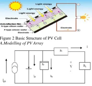
PV cells are made of semiconductor materials, for example, silicon. For solar cells, a thin semiconductor wafer is uniquely treated to shape an electric field, positive on one side and negative on the other. At the point when light vitality strikes the solar cell, electrons are thumped free from the iotas in the semiconductor material. On the off chance that electrical conveyors are appended to the positive and negative sides, framing an electrical circuit, the electrons can be caught as an electric current - that is, electricity. This electricity can then be utilized to power a load. A PV cell can either be round or square in development.
Figure 2 Basic Structure of PV Cell
A.Modelling of PV Array
Figure 3 Equivalent circuit of a PV cell
The building block of PV arrays is the solar cell, which is basically a p-n junction that directly converts light energy into electricity: it has a equivalent circuit as shown below in Figure 3.
The current source Iph represents the cell photo current; Rj is used to represent the non-linear impedance of the p-n junction; Rsh and Rs are used to represent the intrinsic series and shunt resistance of the cell respectively. Usually the value of Rsh is very large and that of Rs is very small, hence they may be neglected to
simplify the analysis. PV cells are grouped in larger units called PV modules which are further interconnected in series-parallel configuration to form PV arrays or PV generators[3].The PV mathematical model used to simplify our PV array is represented by the equation:
where I is the PV array output current; V is the PV array output voltage; ns is the number of cells in series and np is the number of cells in parallel; q is the charge of an
electron; k is the Boltzmann’s constant; A is the p-n
junction ideality factor; T is the cell temperature (K); Irs is the cell reverse saturation current. The factor A in equation (3.5) determines the cell deviation from the ideal p-n junction characteristics; it ranges between 1-5 but for our case A=2.46 [3].
The cell reverse saturation current Irs varies with temperature according to the following equation:
Where Tr is the cell reference temperature, Irr is the cell reverse saturation temperature at Tr and EG is the band gap of the semiconductor used in the cell.
The temperature dependence of the energy gap of the semi conductor is given by [20]:
The photo current Iph depends on the solar radiation and cell temperature as follows:
whereIscr is the cell short-circuit current at reference temperature and radiation, Ki is the short circuit current temperature coefficient, and S is the solar radiation in mW/cm2. The PV power can be calculated using equation (3.5) as follows:
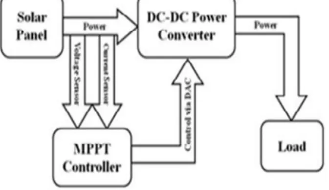
III. MAXIMUM POWER POINT TRACKING SYSTEM
Most extreme power point following is a basic piece of a photovoltaic system. Photovoltaic systems have an unmistakable working point that gives most extreme power. A MPPT actively looks for this working point. Most extreme Power Point Tracking, typically known as MPPT, is an electronic course of action that discover the voltage (VMPP) or current (IMPP) routinely at which a PV modules ought to work to accomplish the greatest power yield (PMPP) under quickly changing ecological conditions. It works the PV modules in a way that allows the modules to create all the power they are able to do.
Solar illumination that hits the photovoltaic modules has a variable character contingent upon the scope, introduction of the solar field, the season and hour of the
www.ijseat.com
* Corresponding Author
Page 496
International Journal of Science Engineering and Advance
Technology, IJSEAT, Vol. 5, Issue 5
ISSN 2321-6905
May-2017
dispersion organize due to non-straight loads in the system.
This paper is composed as takes after Section II gives outline on PV cell, its fundamental hypothesis, associations demonstrating and impact of temperature and illumination on PV board. Area III depicted MPPT P and O calculation and its usage for most extreme power extraction from a PV system associated with a DC/DC Boost converter and its need in PV power era alongside its waveforms. Segment IV presents shunt APF plan and its control calculation with execution of shunt APF control strategy for inverter control. Segment V depicts the acquired reproduction results and its exchanges Section VI gives the conclusion along degree for future work.
II. PHOTOVOLTAIC SYSTEMS
PV cells are made of semiconductor materials, for example, silicon. For solar cells, a thin semiconductor wafer is uniquely treated to shape an electric field, positive on one side and negative on the other. At the point when light vitality strikes the solar cell, electrons are thumped free from the iotas in the semiconductor material. On the off chance that electrical conveyors are appended to the positive and negative sides, framing an electrical circuit, the electrons can be caught as an electric current - that is, electricity. This electricity can then be utilized to power a load. A PV cell can either be round or square in development.
Figure 2 Basic Structure of PV Cell
A.Modelling of PV Array
Figure 3 Equivalent circuit of a PV cell
The building block of PV arrays is the solar cell, which is basically a p-n junction that directly converts light energy into electricity: it has a equivalent circuit as shown below in Figure 3.
The current source Iph represents the cell photo current; Rj is used to represent the non-linear impedance of the p-n junction; Rsh and Rs are used to represent the intrinsic series and shunt resistance of the cell respectively. Usually the value of Rsh is very large and that of Rs is very small, hence they may be neglected to
simplify the analysis. PV cells are grouped in larger units called PV modules which are further interconnected in series-parallel configuration to form PV arrays or PV generators[3].The PV mathematical model used to simplify our PV array is represented by the equation:
where I is the PV array output current; V is the PV array output voltage; ns is the number of cells in series and np is the number of cells in parallel; q is the charge of an
electron; k is the Boltzmann’s constant; A is the p-n
junction ideality factor; T is the cell temperature (K); Irs is the cell reverse saturation current. The factor A in equation (3.5) determines the cell deviation from the ideal p-n junction characteristics; it ranges between 1-5 but for our case A=2.46 [3].
The cell reverse saturation current Irs varies with temperature according to the following equation:
Where Tr is the cell reference temperature, Irr is the cell reverse saturation temperature at Tr and EG is the band gap of the semiconductor used in the cell.
The temperature dependence of the energy gap of the semi conductor is given by [20]:
The photo current Iph depends on the solar radiation and cell temperature as follows:
whereIscr is the cell short-circuit current at reference temperature and radiation, Ki is the short circuit current temperature coefficient, and S is the solar radiation in mW/cm2. The PV power can be calculated using equation (3.5) as follows:
III. MAXIMUM POWER POINT TRACKING SYSTEM
Most extreme power point following is a basic piece of a photovoltaic system. Photovoltaic systems have an unmistakable working point that gives most extreme power. A MPPT actively looks for this working point. Most extreme Power Point Tracking, typically known as MPPT, is an electronic course of action that discover the voltage (VMPP) or current (IMPP) routinely at which a PV modules ought to work to accomplish the greatest power yield (PMPP) under quickly changing ecological conditions. It works the PV modules in a way that allows the modules to create all the power they are able to do.
day. Over the span of a day, a shadow might be thrown on the cell that might be predicted, as on account of a working close to the solar field or unforeseeable as those made by mists. Likewise the vitality created by each photovoltaic cell relies on upon the illumination and temperature. From these contemplations, the need to recognize moment by moment that specific point on the V-I normal for the PV generator in which there is the most extreme measure of power exchange to the lattice happens. The produced vitality from PV systems must be amplify as the productivity of solar boards is low. Therefore to get the greatest power, PV system is over and over outfitted with most extreme power point (MPP) tracker. A few MPP interest methods are proposed and actualized as of late
Figure 4 PV curve characteristics
The current to voltage normal for a solar exhibit is non-straight, which makes it hard to decide the MPP. The Figure beneath gives the trademark I-V and P-V bend for settled level of solar illumination and temperature.
Figure 5 Need of MPPT
In view of the approach utilized for era of the control motion and additionally the PV system conduct around the enduring state conditions, they are typically arranged into the accompanying gatherings:
1. Offline strategies
•Open circuit voltage (OCV) strategy
•Short circuit current strategy (SCC)
•Artificial insight 2. Online strategies
•Perturbation and perception strategy (P&O)
•Extremum looking for control strategy (ESC)
•Incremental conductance strategy (Inc Cond). 3. Hybrid strategies
A. Irritate and Observe (P&O)
The most regularly utilized MPPT calculation is P&O technique. This calculation utilizes straightforward criticism plan and minimal measured parameters. In this approach, the module voltage is occasionally given an annoyance and the relating yield power is contrasted and that at the past bothering cycle. In this calculation a slight irritation is acquaint with the system. This bother causes the power of the solar module different. In the event that the power increments because of the irritation then the bother is proceeded in a similar course. After the pinnacle power is achieved the power at the MPP is zero and next moment diminishes and thus after that the bother inverts.
At the point when the steady condition is arrived the calculation wavers around the pinnacle power point. To keep up the power variety little the bother size is stay little. The procedure is progressed in such a style, to the point that it sets a reference voltage of the module comparing to the pinnacle voltage of the module. A PI controller then acts to exchange the working purpose of the module to that specific voltage level. It is watched some power misfortune because of this irritation likewise the neglects to track the most extreme power under quick changing climatic conditions. Yet, remain this method is exceptionally prevalent and basic.
IV. SHUNT ACTIVE POWER FILTER WITH PV SYSTEM
A Shunt Active Filter (SAPF) is the bidirectional current converter with six switches having combination of both switching network and filter-components. Structure of this power filter is dependent on the control technique of VSI having a capacitor for the purpose of DC energy storage and the inverter output has been connected to Non-linear load having diode Rectifier Bridge with a RL-load. In each of the switches the diodes are connected in anti-parallel arrangement with the IGBTs to permit current flow in either direction. For compensation of reactive power the PV interconnected shunt APF injects real PV power to a distribution line at PCC and also reduces harmonic in load currents caused by nonlinear loads by injecting compensating current. This filter is connected in shunt that means in parallel with the nonlinear load. This active filter has capability of detecting the harmonic currents caused by the nonlinear loads and then injects a current of equal magnitude and opposite in phase with the non-linear load current which is called compensating current to reduce the harmonics present in load currents due to Non-linear load. Hence, the resulting current is in form of a fundamental frequency sinusoidal current which is drawn at PCC in distribution network.
day. Over the span of a day, a shadow might be thrown on the cell that might be predicted, as on account of a working close to the solar field or unforeseeable as those made by mists. Likewise the vitality created by each photovoltaic cell relies on upon the illumination and temperature. From these contemplations, the need to recognize moment by moment that specific point on the V-I normal for the PV generator in which there is the most extreme measure of power exchange to the lattice happens. The produced vitality from PV systems must be amplify as the productivity of solar boards is low. Therefore to get the greatest power, PV system is over and over outfitted with most extreme power point (MPP) tracker. A few MPP interest methods are proposed and actualized as of late
Figure 4 PV curve characteristics
The current to voltage normal for a solar exhibit is non-straight, which makes it hard to decide the MPP. The Figure beneath gives the trademark I-V and P-V bend for settled level of solar illumination and temperature.
Figure 5 Need of MPPT
In view of the approach utilized for era of the control motion and additionally the PV system conduct around the enduring state conditions, they are typically arranged into the accompanying gatherings:
1. Offline strategies
•Open circuit voltage (OCV) strategy
•Short circuit current strategy (SCC)
•Artificial insight 2. Online strategies
•Perturbation and perception strategy (P&O)
•Extremum looking for control strategy (ESC)
•Incremental conductance strategy (Inc Cond). 3. Hybrid strategies
A. Irritate and Observe (P&O)
The most regularly utilized MPPT calculation is P&O technique. This calculation utilizes straightforward criticism plan and minimal measured parameters. In this approach, the module voltage is occasionally given an annoyance and the relating yield power is contrasted and that at the past bothering cycle. In this calculation a slight irritation is acquaint with the system. This bother causes the power of the solar module different. In the event that the power increments because of the irritation then the bother is proceeded in a similar course. After the pinnacle power is achieved the power at the MPP is zero and next moment diminishes and thus after that the bother inverts.
At the point when the steady condition is arrived the calculation wavers around the pinnacle power point. To keep up the power variety little the bother size is stay little. The procedure is progressed in such a style, to the point that it sets a reference voltage of the module comparing to the pinnacle voltage of the module. A PI controller then acts to exchange the working purpose of the module to that specific voltage level. It is watched some power misfortune because of this irritation likewise the neglects to track the most extreme power under quick changing climatic conditions. Yet, remain this method is exceptionally prevalent and basic.
IV. SHUNT ACTIVE POWER FILTER WITH PV SYSTEM
www.ijseat.com
* Corresponding Author
Page 498
International Journal of Science Engineering and Advance
Technology, IJSEAT, Vol. 5, Issue 5
ISSN 2321-6905
May-2017
Figure 6 the flow chart of the P&O algorithm
Fig.7 Schematic diagram of a PV system connected to a Shunt APF
A Shunt APF generally consists of the following Blocks:
і) IGBT based voltage source inverter (VSI) ii) DC
energy storage
iii) Active control unit 1 p–q theory Based Control Akagi et al in 1983 [3] developed P-Q theory or
“instantaneous active-reactive Power theory” for
controlling the active filters. This can be achieved by
transforming the voltage and load current into α-β co
-ordinates.
Fig.8 Block diagram of p-q compensation theory
V. SIMULATION RESULTS
A. Conventional Simulation Circuit
Fig 9 Conventional Simulation Circuit
Fig 10 VSC with Filter
(i) Case Study for Balanced and unbalanced load: To analyze the performance of the proposed system under balanced and unbalanced load conditions, source voltage as well as source current is set as sinusoidal but not in phase. The SAF is required to compensate the reactive power only. At t=0.05 to 0.4, the inverter is switched on. At this instant the inverter starts injecting the compensating current so as to compensate the phase difference between the source voltage and current. The supply current is the sum of load current and injected SAF output current. During the initial period, there is no load deviation in the load. Hence, the programmable three-phase AC voltage source feeds the total active power to the load. Figure 7.3 shows the waveforms of (a) Grid Current,
(b) Load Current, (c) Inverter current. The real power generated from PV system is supply to the load required demand.
www.ijseat.com
* Corresponding Author
Page 498
International Journal of Science Engineering and Advance
Technology, IJSEAT, Vol. 5, Issue 5
ISSN 2321-6905
May-2017
Figure 6 the flow chart of the P&O algorithm
Fig.7 Schematic diagram of a PV system connected to a Shunt APF
A Shunt APF generally consists of the following Blocks:
і) IGBT based voltage source inverter (VSI) ii) DC
energy storage
iii) Active control unit 1 p–q theory Based Control Akagi et al in 1983 [3] developed P-Q theory or
“instantaneous active-reactive Power theory” for
controlling the active filters. This can be achieved by
transforming the voltage and load current into α-β co
-ordinates.
Fig.8 Block diagram of p-q compensation theory
V. SIMULATION RESULTS
A. Conventional Simulation Circuit
Fig 9 Conventional Simulation Circuit
Fig 10 VSC with Filter
(i) Case Study for Balanced and unbalanced load: To analyze the performance of the proposed system under balanced and unbalanced load conditions, source voltage as well as source current is set as sinusoidal but not in phase. The SAF is required to compensate the reactive power only. At t=0.05 to 0.4, the inverter is switched on. At this instant the inverter starts injecting the compensating current so as to compensate the phase difference between the source voltage and current. The supply current is the sum of load current and injected SAF output current. During the initial period, there is no load deviation in the load. Hence, the programmable three-phase AC voltage source feeds the total active power to the load. Figure 7.3 shows the waveforms of (a) Grid Current,
Fig 11 Grid, Load, Filter Current waveforms (Filter on from 0.05 to 0.4)
During the unbalanced load condition, the transient load current changes occur. The Active Power filter is switched on at time between t = 0.05 to 0.4. From figure 11 it is observed that the Grid current is distorted from t= 0 to 0.05. At 0.05 filter is switched on then the current oscillates at 0.05 and it stabilizes at 0.1 and again the grid current gets distorted due to the switch off of filter at 0.4
Fig 12 Conventional Circuit THD analysis without filter (16.03%)
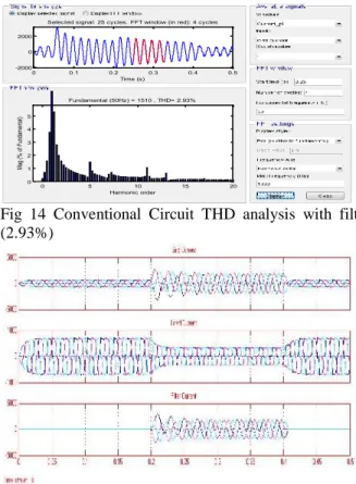
Fig 13 Grid, Load, Filter Current waveforms (Filter on from 0.05 to 0.4)
Fig 14 Conventional Circuit THD analysis with filter (2.93%)
Fig 15 Proposed Method Grid, Load, Filter Current waveforms (Filter on from 0.2 to 0.4)
Fig 16 Proposed Circuit THD analysis with filter (1.91%)
It is observed that it shows a good dynamic response of APF when a droop control method is applied to it. The FFT of the grid current with conventional and proposed method is carried out. The current THD is reduced from 2.93% to 1.91% as shown in Fig.16.
Comparison table
THD Value
Without Filter THD 16.03 Conventional circuit THD 2.93 Proposed circuit THD 1.91
VI. CONCLUSION
0 0.1 0.2 0.3 0.4 0.5 -2000
0 2000
Selected signal: 25 cycles. FFT window (in red): 4 cycles
Time (s)
0 5 10 15 20
0 5 10 15 20
Harmonic order Fundamental (50Hz) = 599.6 , THD= 16.03%
M
ag
(%
o
f F
un
da
m
en
ta
l)
0 0.1 0.2 0.3 0.4 0.5
-2000 0 2000
Selected signal: 25 cycles. FFT window (in red): 4 cycles
Time (s)
0 5 10 15 20
0 1 2 3 4 5
Harmonic order Fundamental (50Hz) = 1510 , THD= 2.93%
Ma
g (
%
of
Fu
nd
am
en
tal
)
0 0.1 0.2 0.3 0.4 0.5 -3000
-2000 -1000 0 1000
Selected signal: 25 cycles. FFT window (in red): 4 cycles
Time (s)
0 5 10 15 20
0 2 4 6 8
Harmonic order Fundamental (50Hz) = 1894 , THD= 1.91%
M
ag
(%
o
f F
un
da
m
en
ta
www.ijseat.com
* Corresponding Author
Page 500
International Journal of Science Engineering and Advance
Technology, IJSEAT, Vol. 5, Issue 5
ISSN 2321-6905
May-2017
In this paper the Simulink implementation of grid connected inverter control technique has done by SIMULINK where the inverter control involves the P-Q compensation theory and hysteresis control for generation of gate pulse for the VSI. This inverter control is applied at the PCC to get the sinusoidal load current. The load current before and after inverter control application is done by Simulink and the waveforms shows the effect of inverter control, where the result after inverter control is almost sinusoidal with less harmonic content. For the THD analysis of load current before and after the inverter control technique application, on the SIMULINK page FFT analysis option in the powergui is chosen which results in display of THD percentage of the load current before and after compensation. Hence, it is seen that in case of inverter control technique total harmonic distortion in load current is 16.03% before inverter control and it reduces to 1.91% after inverter control and also grid current is in same phase with grid voltage that is unity power factor(UPF) occurs. So inverter plays a novel role to control the harmonics and reactive power compensation to provide only real power at the PCC of the distribution system. Hence, it can be concluded that by use of Shunt APF the harmonics due a non-linearity of load is compensated to a large value to provide sinusoidal output current of multiple of fundamental frequency and also reactive power is compensated to provide only real power at the distribution system.
REFERENCES
[1]B. Subudhi, R. Pradhan, “ A Comparative Study on
Maximum Power Point Tracking Techniques for
Photovoltaic Power Systems” IEEE Transactions on
Sustainable energy, vol. 4, no. 1, January 2013.
[2] H. Akagi, “Instantaneous Power Theory and
Applications to Power Conditioning”, February
2007, Wiley-IEEE Press.
[3] R. Panigrahi, B. Subudhi and P. C Panda, “Model
predictive-based shunt active power filter with a new
reference current estimation strategy”, IET Power
Electron., 2015, Vol. 8, Iss. 2, pp. 221–233.
[4] H. Akagi, Y. Kanmwva, K. Fujiia, A. Nabae,
“Generalized Theory of the instantaneous Reactive
Power and its Application”, Trans. IEEE Vol. 103-H,
No. 7. 1983.
[5]J. Harada and G. Zhao, “Controlled power-interface
between solar cells and ac sources,”in IEEE Conf., 1989, pp. 22.1/1-22.1/7.
[6]Moleykutty George and Kartik Prasad Basu “Three
-Phase Shunt Active Power Filter “American Journal of
Applied Sciences 5 (8), 2008 pp.909-916.
[7] AymanBlofan, Patrice Wira,”PV energy generation
for an autonomous shunt active power filter”, 2011.
[8]H. Akagi, “New Trends in Active Filters for Power
Conditioning,” IEEE Trans. on Industry Applications,
1996, vol. 32, no. 6, pp. 1312-1322.
[9] Hiren Patel and Vivek Agarwal, “Maximum
Power Point Tracking Scheme for PV Systems
Operating Under Partially Shaded Conditions”, IEEE
Transactions on Industrial Electronics, Vol.55, No.4, pp 1689-1698, 2008.
[10] T. Esram and P. L. Chapman, “Comparison of
photovoltaic array maximum power point tracking
techniques,” IEEE Trans. on Energy Conversion, vol.
22, no. 2, June 2007.
[11] M. C. Benhabib and S. Saadate, “New Control
approach for four wire active power filter based on the use of synchronous reference frame,” Elsevier Electric
power systems Research 73, 2005, 353-362.
[12] Eswaran Chandra Sekaran , “Analysis and
simulation of a new shunt active Power filter using
cascaded multilevel inverter” Journal of electrical
engineering, vol. 58, no. 5, 2007, 241–249.
[13] B. Boukezata, A.Chaoui, J P. Gaubert and M.
Hachemi, “Active Power Filter in a transformer-less
Grid Connected Photovoltaic System” Balkan Journal of
electrical & computer engineering, 2014, vol.2, no.3.
[14]M. Park, N.G. Seong and I.K. Yu, “A Novel
Photovoltaic Power Generation System including the
Function of Shunt Active Filter,” KIEE International
Transactions on EMECS, Vol. 3B-2, pp. 103- 110, June, 2003.
[15] M. Elshaer, A. Mohamed, and O. Mohammed,
“Smart Optimal Control of DC-DC Boost Converter in
PV Systems” IEEE Transmission and Distribution
Conference and Exposition Latin America, 2010, pp. 978-1-4577-0487-1/10.
[16] Zulkifile Ibrahim, “Performance investigation of
photovoltaic grid connection for shunt active power filter with different PWM generation” 20th November
2013. Vol. 57 No.2.
[17]Ahmed M. Atallah, “Implementation of perturb and
method using buck and buck-boost Converters
Emerging Trends in Electrical”, Electronics &
Instrumentation Engineering: An International Journal(EEIEJ), Vol. 1, No. 1, February 2014.
[18] AymanBlorfan, Patrice Wira, “A three-phase
hybrid active power filter With photovoltaic generation and Hysteresis current control” 2011 IEEE.
[19] RachidBelaidi, “Shunt active power filter
connected to a photovoltaic array for compensating
harmonics and reactive power simultaneously” 4th
International Conference on Power Engineering, Energy and Electrical Drives Istanbul, 13-17 May 2013 IEEE, Turkey.
[20] A.S. Abu Hasim, “Photovoltaic System
Connected to Three Phase Grid Connected System
Incorporating With Active Power Filter” Australian
Journal of Basic and Applied Sciences, 345-353, 2012 ISSN 1991-8178.
[21] Jeevananthan K.S, “Designing of Single Phase
Shunt Active Filter Using Instantaneous Power Theory”
International Journal of Electrical and Electronics Research Vol. 2, Issue 2, pp: (1-10), Month: April - June 2014.
[22] T.Chaitanya, “Modeling and Simulation of PV
Array and its Performance Enhancement Using MPPT
(P&O) Technique” International Journal of Computer
Science & Communication Networks, Vol 1(1), September-October 2011.
[23]Thomas Geury,“Three-phase Power Controlled PV
Current Source Inverter with Incorporated Active Power
Filtering”, 2013 IEEE.
[24] Remya A.V, “Grid interconnection of PV system
for 3 phase 4 wire Distribution system with
power-quality improvement” International Conf. on Electrical,