4 Port Router/Switch (P/N 364772-02-V1)
User’s Guide
IS-1507035 REV. A
La version française de ce Guide de l’utilisateur se trouve sur notre site web à
www.legrand.us/onq
La versión en español de esta Guía del usuario se encuentra en nuestro sitio web en www.legrand.us/onq
FCC Certifications
This equipment generates and uses radio frequency energy and if not installed and used properly, that is, in strict accordance with the instructions provided with the equipment, may cause interference to radio and TV communication. The equipment has been tested and found to comply with the limits for a Class A computing device in accordance with the specifications in Subpart B of Part 15 of FCC rules, which are designed to provide reasonable protection against such interference in a residential installation. However, there is no guarantee that interference will not occur in a particular installation. If you suspect this equipment is causing interference, turn your Router/Switch on and off while your radio or TV is showing interference, if the interference disappears when you turn your Router/Switch off and reappears when you turn it back on, there is interference being caused by the Router/Switch.
You can try to correct the interference by one or more of the following measures:
Reorient the receiving radio or TV antenna where this may be done safely.
To the extent possible, relocate the radio, TV or other receiver away from the Router/Switch.
Plug the Router/Switch into a different power outlet so that the Router/Switch and the receiver are on different branch circuits.
If necessary, you should consult the place of purchase or an experienced radio/television technician for additional suggestions.
CE Mark Warning
This is a class B device, In a domestic environment, this product may cause radio interference, in which case the user may be required to take adequate measures.
All trademarks and brand names are the property of their respective proprietors. Specifications are subject to change without prior notification.
TABLE OF CONTENTS
1.0 Introduction ... 1
1.1 Features ... 2
1.2 Minimum Requirements ... 3
1.3 Detailed Physical Description ... 4
1.4 Installation ... 5
1.5 Initial Configuration ... 6
2.0 Quick Setup ... 8
2.1 Dynamic IP ... 10
2.2 Static IP ... 11
2.3 PPPoE ... 12
2.4 PPTP ... 13
2.5 L2TP ... 14
Appendix A ... 16
Glossary ... 17
1.0 Introduction
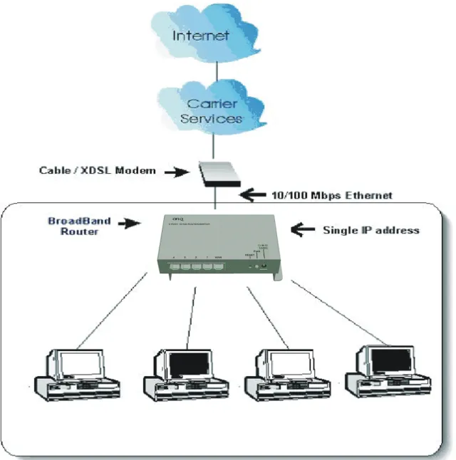
The Legrand 4 Port Router/Switch is an integrated Internet IP sharing device with a built-in 4-port 10/100Mbps Fast Ethernet switch. It is the perfect solution to connect a small group of PCs to a high-speed broadband Internet connection (see Figure 1). Up to 253 users can have high-speed Internet access simultaneously via one single IP address (Internet account) of the Cable/xDSL modem.
With its built in NAT technology, this product also serves as an Internet firewall, protecting your network from being accessed by outside users. All incoming data packets are monitored and filtered. The Router can also be configured with Client Filtering, to filter internal users’ access to the Internet. The built-in 4-port Fast Ethernet Switch lets users plug the network cable into the device without buying additional Hub/Switch.
1.1
Features
Internet Access Features
Shared Internet Access: All users on the LAN can access the Internet through
the Router/Switch using only a single external IP Address. The local (invalid) IP Addresses are hidden from external sources. This process is called NAT (Network Address Translation).
Multiple WAN Connection: On the Internet (WAN port) connection, the
Router/Switch supports Dynamic IP Address (IP Address is allocated on connection), Fixed IP Address, PPPoE, PPTP and L2TP.
Bridge and Router Application: The Router/Switch supports two application
modes. Currently, it comes pre-configured with Router mode. Note that, Router mode and Bridge mode cannot be used simultaneously.
Advanced Internet Functions
Quick Setup: Built-In configuration wizard helps users to complete network
installation in a very short time via standard Internet browsers such as Microsoft Internet Explorer, Netscape Communicator…etc.
QoS: Quality of service can classify the network packet based on the port base
and DSCP; it can provide the best effect for real-time streaming multimedia applications such as the on-line gaming, VoIP, and IPTV.
Virtual Servers: This feature allows Internet users to access Internet servers on
your LAN. The required setup is quick and easy.
Universal Plug and Play (UPnP): UPnP allows automatic discovery and
configuration of the Broadband Router. UPnP is supported by Windows ME, XP, or later.
User Friendly Interface: The Router/Switch can be managed and controlled
through Web UI.
DMZ Support: The Router/Switch can translate public IP addresses to private IP
address to allow unlimited 2-Way communication with the servers or individual users on the Internet. It provides the most flexibility to run programs smoothly for programs that might be restricted in NAT environment.
SPI Firewall: Built in NAT firewall with Stateful Packet Inspection for DoS
(Denial of Service) attacks.
Client / URL / MAC Filtering: The Filtering function can block the unallowable
LAN users accessing to Internet. Or you can use the keyword based URL Filter to block access to undesirable Web sites by LAN users.
RIP1/2 Routing: It supports RIPv1/2 routing protocol for routing capability. VPN Pass through Support: PCs with VPN (Virtual Private Networking)
software are transparently supported - no configuration is required.
LAN Features
4-Port Switch: The Router/Switch incorporates a 4-port 10/100Base-TX
DHCP Server Support: Dynamic Host Configuration Protocol provides a
dynamic IP address to PCs and other devices upon request. The Router/Switch can act as a DHCP Server for devices on your local LAN.
1.2 Minimum Requirements
One External xDSL (ADSL) or Cable modem with an Ethernet port (RJ-45) Network Interface Card (NIC) for each Personal Computer (PC)
PCs with a Web-Browser (Internet Explorer 4.0 or higher, or Netscape Navigator 4.7 or higher)
1.3 Detailed Physical Description
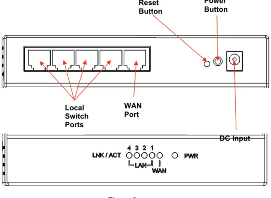
Router/Switch Module Connection AreaFigure 2 shows the Router/Switch connection area including:
DC Input connector – connection from power supply
WAN (Internet) Port – 8 position RJ-45 jack (connects to Cable or DSL modem) Local Switch Ports – 8 position RJ-45 jacks (connection from outlets in rooms) Power Button – Turns power on/off to router/switch.
Reset Button - A button press (over 3 seconds) resets the Router/Switch unit to the factory default settings. This clears all user settings, including User Name, Password, IP Address, and Subnet Mask.
NOTE: Refer to InitalConfiguration section for instructions on re-configuring the Router/Switch.
Router/Switch Status LEDs (see Figure 2)
Power – On solid green when power is supplied. Link/Act Local Port and WAN Port LEDs
Link/Act – On solid green indicates functional LAN or WAN link through the port with the attached device. Off means no LAN or WAN connection.
Figure 2
STATUS
DC Input Reset
Button
WAN Port Local
Switch Ports
Power Button
1.4 Installation
The 4 Port Router/Switch is best installed during new construction in two steps; at “rough-in” after the Electricians are done, but prior to drywall being installed, and at “trim-out” after the drywall is installed and painted. These steps are detailed below:
A. “Rough-in” steps:
1. A single dedicated Cat 5e should be run in the walls from the structured wiring enclosure location in the home where the 4 Port Router/Switch will be installed to each outlet location in the rooms where Internet service is required (leave extra cable at both ends).
NOTE: Run Cat 5e cable at least 12” from electrical cabling (preferably in a separate stud cavity) and cross electrical cables at a 90° angle. Use loose Velcro-style cable ties for bundling. If stapling is required, use specialty staples to avoid compressing the cable. 2. At the selected outlet locations, a single gang box or low voltage bracket should be installed,
with the extra Cat 5e cable in the box, or attached in such a way that it may be fished out after the drywall is installed.
B. “Trim-out” steps:
1. The Cat 5e that was secured at each of the outlets should be pulled out and terminated with a 110 punchdown tool on an RJ45 insert and attached to a wallplate, which is then installed in the single gang box or low voltage bracket.
2. In the structured wiring enclosure the Cat 5e from the outlets may be terminated with RJ-45 plugs, using a tool such as our EZ RJ45 Modular Plug Hand Toll (P/N 364555-01) for direct connection to the 4 Port Router/Switch.
3. The 4 Port 10/100 Router/Switch is installed in the structured wiring enclosure by slipping the tabs into the square holes, and using the push pin in a round hole to secure the router. 4. An additional Cat 5e cable is then connected from the network (WAN) port of the 4 Port
10/100 Router/Switch to the Cable Modem or DSL Modem housed in the structured wiring enclosure.
5. The 4 Port 10/100 Router/Switch is powered with an AC to DC adapter which also needs to be plugged in to an AC source.
6. Follow the steps in the next two sections for configuring the router.
NOTE: Use proper tools and standard TIA 568A rules to prep and terminate the Cat 5e cable, such as a Cat 5 Cable Stripper, an RJ45 Crimp Tool and a 110 Punchdown Tool.
1.5 Initial Configuration
The 4 Port Router/Switch is typically configured in one of two ways; (1) From a portable PC
connected through one of the Local Switch Ports on the Router/Switch Module in the enclosure, or (2) From a PC in one of the rooms of the house, connected through an outlet in the room to the
enclosure where it is patched to (or directly connected to) one of the Local Switch Ports (see Figure 3). In either case, the PC must have an Ethernet Network Interface Card to communicate with the Router/Switch.
A. Configuring a Network Interface Card to talk to the Router/Switch
NOTE: The steps below assume that your PC’s network interface card is set to DHCP, or in other words, to obtain IP addressing automatically. The steps also assume that the 4 Port Router/Switch is set to its default settings and that all the cables previously discussed are properly connected. It is also possible to perform these steps by configuring your computer (with installed Ethernet Network Interface Card) to talk to the Router/Switch on its specific IP subnetwork (192.168.40.xxx). The Router/Switch’s default IP address in that subnetwork is 192.168.40.254, so your PC’s Ethernet Card can be temporarily assigned an IP address, (like 192.168.40.10), on that same subnetwork to talk to and configure the Router/Switch. Giving the PC a specific IP address is also called assigning it a Static IP address, as compared to a Dynamic IP address that is typically assigned by a service provider when your PC’s network interface card is configured for Dynamic Host Configuration Protocol (DHCP).
NOTE: Before doing any PC IP Address re-configuration, make sure you first write down all of the current IP settings. XP users can set “last known useable configuration” under System Accessories before re-configuring.
B. Logging on to the Router/Switch
1. With your PC connected to one of the local ports on the Router/Switch, open a browser and enter the Router/Switch’s default IP address (192.168.40.254), and click “Go” (see Figure 4) to get the login page.
2. To logon, enter “admin” for the user name and password and just click OK (see Figure 5).
3. Figure 6 shows the System Status screen that you will see once you have logged on. By clicking on the word WIZARD in the upper left corner, the Setup Wizard will lead you step-by-step through the initial configuration of the Router.
NOTE: You can also manually configure the Router/Switch by clicking on a function listed across the top of the page, such as “SYSTEM” to change your User Name or Password, perform a firmware upgrade, restore factory defaults, or backup/restore system settings. You could also click on “WAN” to configure your network connection type, or “LAN” to identify the starting IP address for the LAN ports, or “NAT” or “FIREWALL” or “DDNS” to configure those functions.
Figure 4
Figure 5 192.168.40.254
admin
2.0 Quick Setup
The Wizard section is designed to get you using Router/Switch as quick as possible. In the Wizard, you are required to fill in only the information necessary to access the Internet. Once you click on the Wizard in the web page, you should see the screen below.
Step 1) Host Settings
The Host Settings allows your router to set up Host name and Domain name, it also can set up its Time Zone and Daylight Saving Time, these will affect functions such as Log entries and Firewall settings.
Parameter Description
Host Name Optional. You can specify a Host name for the Router/Switch.
Time Zone Select the time zone of the country where you currently are.
The router will set its time based on your selection.
Daylight Savings The Router/Switch can also take Daylight savings into
account. If you wish to use this function, you must select the enable box to enable your daylight saving configuration.
Click on NEXT to proceed to the next page (step 2) WAN Settings.
Step 2) WAN Settings
In this section you have to select one of these types of connections that you will be using to connect your Router/Switch’s WAN port to your ISP (see screen below).
"
Note Different ISP’s require different methods of connecting to the Internet, please check with your ISP as to the type of connection it requires.Parameter Description
Dynamic IP Your ISP will automatically give you an IP address.
Static IP Your ISP has given you an IP address already
PPPoE Your ISP requires you to use a Point-to-Point Protocol over
Ethernet (PPPoE) connection.
PPTP Your ISP requires you to use a Point-to-Point Tunneling
Protocol (PPTP) connection.
L2TP Layer 2 Tunneling Protocol is a common connection method used in xDSL connections.
2.1 Dynamic IP
Choose Dynamic IP if your ISP will automatically give you an IP address. Some ISP’s may also require that you fill in additional information such as MAC address (see screen below).
"
NoteThe MAC address section is optional and you can skip this section if your ISP does not require these settings for you to connect to the Internet.
Parameter Description
MAC Cloning If you want to clone your PC’s MAC address to the Router/Switch,
you must enable it first.
MAC Address Your ISP may require a particular MAC address in order for you to
connect to the Internet. This MAC address is the PC’s MAC address that your ISP had originally connected your Internet connection to. Type in this MAC address in this section or use the
Clone MAC Address button to replace the WAN MAC address
with the MAC address of that PC (you have to be using that PC for the Clone MAC Address button to work).
2.2 Static IP
Select Static IP if your ISP has given you a specific IP address to use. Your ISP should provide all the information required in this section.
Parameter Description
IP address assigned by your ISP
This is the IP address that your ISP has given you.
Subnet Mask Enter the Subnet Mask provided by your ISP.
(e.g. 255.255.255.0)
2.3 PPPoE
Select PPPoE if your ISP requires the PPPoE protocol to connect you to the Internet. Your ISP should provide all the information required in this section.
Parameter Description
User Name Enter the User Name provided by your ISP for the PPPoE
connection.
Password Enter the Password provided by your ISP for the PPPoE
connection.
Retype Password Re-enter the Password for confirmation.
Service Name This is optional. Enter the Service name should your ISP
requires it, otherwise leave it blank.
MTU This is optional. You can specify the maximum size of your transmission packet to the Internet. Leave it as it is if you do not wish to set a maximum packet size. (The default settings is 1492)
Maximum Idle Time You can specify an idle time threshold (seconds) for the WAN
port. This means if no packets have been sent (no one using the Internet) during this specified period, the router will automatically disconnect the connection with your ISP. (The default settings is 300 seconds)
2.4 PPTP
Select PPTP if your ISP requires the PPTP protocol to connect you to the Internet. Your ISP should provide all the information required in this section.
Parameter Description
PPTP Account Enter the PPTP Account provided by your ISP for the PPTP
connection.
PPTP Password Enter the Password provided by your ISP for the PPTP
connection.
Retype Password Re-enter the Password for confirmation.
Service IP Address Specify PPTP Server IP address that you want to connect to.
My IP Address This is the IP address that your ISP has given you to
establish a PPTP connection.
My Subnet Mask Enter the Subnet Mask provided by your ISP.
(e.g. 255.255.255.0)
Gateway Address This is the ISP’s IP address gateway.
MTU This is optional. You can specify the maximum size of your transmission packet to the Internet. Leave it as it is if you do not wish to set a maximum packet size. (The default setting is 1460)
Maximum Idle Time You can specify an idle time threshold (seconds) for the WAN
2.5 L2TP
Select L2TP if your ISP requires the L2TP protocol to connect you to the Internet. Your ISP should provide all the information required in this section.
Parameter Description
L2TP Account Enter the L2TP Account provided by your ISP for the PPTP
connection.
L2TP Password Enter the Password provided by your ISP for the L2TP
connection.
Retype Password Re-enter the Password for confirmation.
Service IP Address Specify L2TP Server IP address that you want to connect to.
My IP Address This is the IP address that your ISP has given you to
establish a L2TP connection.
My Subnet Mask Enter the Subnet Mask provided by your ISP. (e.g.
255.255.255.0)
Gateway Address This is the ISP’s IP address gateway.
MTU This is optional. You can specify the maximum size of your transmission packet to the Internet. Leave it as it is if you do not wish to set a maximum packet size. (Default setting is 1460)
Maximum Idle Time You can specify an idle time threshold (seconds) for the WAN
port. This means if no packets have been sent (no one using the Internet) during this specified period, the router will automatically disconnect the connection with your ISP. (The default settings is 300 seconds)
Step 3) DNS
A Domain Name System (DNS) server is like an index of IP addresses and Web addresses. If you type a Web address into your browser, such as www.router.com, a DNS server will find that name in its index and the matching IP address. Most ISPs provide a DNS server for speed and convenience. If your Service Provider connects you to the Internet with dynamic IP settings, it is likely that the DNS server IP address is provided automatically. However, if there is a DNS server that you would rather use, you need to specify the IP address of that DNS server here.
Parameter Description
Static DNS Server Select “Enabled” to allow configuring DNS manually.
Primary DNS Address This is the ISP’s DNS server IP address that they gave
you; or you can specify your own preferred DNS server IP address
Secondary DNS Address This is optional. You can enter another DNS server’s IP
address as a backup. The secondary DNS will be used if the above DNS fail.
Click <Finish> when you have finished the configuration above. Congratulations! You have completed the connection configuration. You can start using the router now.
Appendix A
How to Manually find your PC’s IP and MAC address
1) In Window’s open the Command Prompt program
2) Type ipconfig /all and <enter>
• Your PC’s IP address is the one entitled IP address (192.168.0.7 in the example) • The router’s IP address is the one entitled Default Gateway (192.168.0.1 in the example)
Glossary
Default Gateway (Router): Every non-router IP device needs to configure a default gateway’s IP address. When the device sends out an IP packet, if the destination is not on the same network, the device has to send the packet to its default gateway, which will then send it out towards the destination.
DHCP: Dynamic Host Configuration Protocol. This protocol automatically gives every computer on your home network an IP address.
DNS Server IP Address: DNS stands for Domain Name System, which allows Internet
servers to have a domain name (such as www.Broadbandrouter.com) and one or more IP addresses (such as 192.34.45.8). A DNS server keeps a database of Internet servers and their respective domain names and IP addresses, so that when a domain name is requested (as in typing "www.legrand.us/onq" into your Internet browser), the user is sent to the proper IP address. The DNS server IP address used by the computers on your home network is the location of the DNS server your ISP has assigned to you.
DSL Modem: DSL stands for Digital Subscriber Line. A DSL modem uses your existing
phone lines to transmit data at high speeds.
Ethernet: A standard for computer networks. Ethernet networks are connected by special cables and hubs, and move data around at up to 10/100 million bits per second (Mbps).
Idle Timeout: Idle Timeout is designed so that after there is no traffic to the Internet for a preconfigured amount of time, the connection will automatically be disconnected.
IP Address and Network (Subnet) Mask: IP stands for Internet Protocol. An IP address consists of a series of four numbers separated by periods, that identifies a single, unique Internet computer host in an IP network. Example: 192.168.0.1. It consists of 2 portions: the IP network address, and the host identifier.
The IP address is a 32-bit binary pattern, which can be represented as four cascaded decimal numbers separated by “ aaa.aaa.aaa.aaa”, where each “aaa” can be anything from 000 to 255, or as four cascaded binary numbers separated by
“bbbbbbbb.bbbbbbbb.bbbbbbbb.bbbbbbbb”, where each “b” can either be 0 or 1. A network mask is also a 32-bit binary pattern, and consists of consecutive leading 1’s followed by consecutive trailing 0’s, such as
11111111.11111111.11111111.00000000. Therefore sometimes a network mask can also be described simply as “x” number of leading 1’s.
When both are represented side by side in their binary forms, all bits in the IP address that
It means the device’s network address is 11011001.10110000.10010000.00000000, and its host ID is, 00000000.00000000.00000000.00000111. This is a convenient and efficient method for routers to route IP packets to their destination.
ISP Gateway Address: (see ISP for definition). The ISP Gateway Address is an IP address forthe Internet router located at the ISP's office.
ISP: Internet Service Provider. An ISP is a business that provides connectivity to the Internet for individuals and other businesses or organizations.
LAN: Local Area Network. A LAN is a group of computers and devices connected
together in a relatively small area (such as a house or an office). Your home network is considered a LAN.
MAC Address: MAC stands for Media Access Control. A MAC address is the hardware
address of a device connected to a network. The MAC address is a unique identifier for a device with an Ethernet interface. It is comprised of two parts: 3 bytes of data that corresponds to the Manufacturer ID (unique for each manufacturer), plus 3 bytes that are often used as the product’s serial number.
NAT: Network Address Translation. This process allows all of the computers on your home network to use one IP address. Using the Router/Switch’s NAT capability, you can access the Internet from any computer on your home network without having to purchase more IP addresses from your ISP.
Port: Network Clients (LAN PC) uses port numbers to distinguish one network application/protocol over another. Below is a list of common applications and protocol/port
PPPoE: Point-to-Point Protocol over Ethernet. Point-to-Point Protocol is a secure data transmission method originally created for dial-up connections; PPPoE is for Ethernet connections. PPPoE relies on two widely accepted standards, Ethernet and the Point-to-Point Protocol. It is a communications protocol for transmitting information over Ethernet between different manufacturers
Protocol: A protocol is a set of rules for interaction agreed upon between multiple parties so that when they interface with each other based on such a protocol, the interpretation of their behavior is well defined and can be made objectively, without confusion or misunderstanding.
Router: A router is an intelligent network device that forwards packets between different networks based on network layer address information such as IP addresses.
Subnet Mask: A subnet mask, which may be a part of the TCP/IP information provided
by your ISP, is a set of four numbers (e.g. 255.255.255.0) configured like an IP address. It is used to create IP address numbers used only within a particular network (as
opposed to valid IP address numbers recognized by the Internet, which must be assigned by InterNIC).
TCP/IP, UDP: Transmission Control Protocol/Internet Protocol (TCP/IP) and Unreliable Datagram Protocol (UDP). TCP/IP is the standard protocol for data transmission over the Internet. Both TCP and UDP are transport layer protocol. TCP performs proper error detection and error recovery, and thus is reliable. UDP on the other hand is not reliable. They both run on top of the IP (Internet Protocol), a network layer protocol.
WAN: Wide Area Network. A network that connects computers located in
geographically separate areas (e.g. different buildings, cities, countries). The Internet is a wide area network.
Web-based management Graphical User Interface (GUI): Many devices support a
graphical user interface that is based on the web browser. This means the user can use the familiar Netscape or Microsoft Internet Explorer to Control/configure or monitor the device being managed.