Best Practices for
Virtualizing & Managing
Exchange 2013
Copyright Information
© 2013 Microsoft Corporation. All rights reserved. This document is provided "as-is." Information and views expressed in this document, including URL and other Internet Web site references, may change without notice. You bear the risk of using it. This document does not provide you with any legal rights to any intellectual property in any Microsoft product. You may copy and use this document for your internal, reference purposes. You may modify this document for your internal, reference purposes.
Table of Contents
Introduction ... 5
Executive Summary ... 5
Target Audience ... 6
Scope ... 6
Why Virtualize Exchange? ... 7
Why Microsoft Virtualization and Management? ... 8
Fabric Configuration ... 9
Hardware Considerations ... 9
Compute Considerations ... 12
Storage Considerations ... 17
Networking Considerations ... 29
Host Resiliency & VM Agility ... 35
Host Clustering ... 35
Virtual Machine Configuration ... 44
General Supportability... 44
Microsoft Assessment and Planning Toolkit ... 44
Exchange 2013 Server Role Requirements Calculator ... 45
Exchange 2013 Virtual Machine CPU Considerations ... 45
Exchange 2013 Virtual Machine Memory Considerations ... 47
Exchange 2013 Virtual Machine Storage Considerations ... 50
Exchange 2013 Virtual Machine Network Considerations ... 54
Exchange 2013 Resiliency ... 60
Single Exchange 2013 Virtual Machine on a Hyper-V Cluster ... 61
Resilient Exchange Configuration on a Hyper-V Cluster ... 62
System Center 2012 SP1 ... 66
Comprehensive Management Capabilities ... 66
Virtual Machine Manager ... 66
App Controller ... 76
Service Manager and Orchestrator ... 78
Operations Manager ... 84
Data Protection Manager ... 87
Conclusion ... 90
Introduction
This guide provides high-level best practices and considerations for deploying and managing Microsoft Exchange 2013 on a Windows Server 2012 Hyper-V-based virtualization infrastructure. The
recommendations and guidance in this document aim to:
Complement the architectural design of an organization’s specific environment.
Help organizations take advantage of the key platform features in Microsoft Exchange 2013 to deliver the highest levels of performance and availability in a virtualized environment.
Executive Summary
To meet demanding and ever-changing business needs, organizations want their Exchange Server-based messaging solution to rapidly scale and to be highly available at all times. As the demand for Exchange Server resources increases within and across organizations, it becomes important for IT to quickly meet those requirements. At the same time, though, IT is challenged with the need to minimize the cost of underlying infrastructure, effectively manage risk, and save time and effort on management activities. One solution to this challenge is virtualization.
Virtualization is now common in organizations of all sizes. Many have moved beyond the nascent stage into being more advanced users of server virtualization for a variety of workloads, including their
messaging systems. These organizations have gained benefits in the areas of cost, efficiency, operations, availability, agility, and resiliency.
Windows Server 2012 Hyper-V, with its enhanced capabilities, can be used to effectively virtualize
mission-critical workloads such as Exchange 2013. This guide explains these capabilities in the context of:
How organizations can virtualize Exchange 2013 on Windows Server 2012 Hyper-V.
How organizations can benefit from managing this virtualized environment with Microsoft System Center 2012 SP1.
Working together, these three industry-leading products deliver an integrated solution that provides low total cost of ownership (TCO) and offers mission-critical scale, performance, and high availability. The solution also provides more enhanced end-to-end security, management, and monitoring capabilities. Further, many organizations now want to go a step beyond and adopt an IT infrastructure that is optimized for and ready to work in a cloud-based environment. They need an IT infrastructure that can seamlessly span from a private to a public cloud. To achieve this goal, many organizations choose a common virtualization platform across the infrastructure. In this regard, Windows Server 2012 Hyper-V offers the best virtualization platform for Exchange 2013.
Target Audience
This guide is intended for IT professionals and technical decision makers (TDMs), including IT consultants and architects, IT managers, and messaging administrators. With this guide, IT professionals can better understand how to set up an environment for virtualizing Exchange 2013 using an integrated
virtualization platform built on some of the latest Microsoft technologies, including Windows Server 2012 Hyper-V and System Center 2012 SP1. In addition, identifying key considerations and best practices can help TDMs effectively plan and deploy Exchange 2013 in a Hyper-V environment. This guide serves the following purposes for these key roles:
IT consultants and architects: Understand how the entire virtualization environment will work as they design the architecture.
IT managers: Design processes to fit the overall virtualization environment so that costs are reduced and efficiency is increased as much as possible.
Messaging administrators: Understand how Exchange 2013 can be set up and function in the virtual environment.
Scope
This guide focuses on providing an understanding of the key considerations for virtualizing Exchange 2013 on a Windows Server 2012 host system or virtual machine, or as part of an on-premises, hybrid, or private cloud deployment. At a broad level, the guide is divided into the following sections:
Fabric configuration: Covers the key requirements, features, and considerations for infrastructure that are necessary to set up the virtualization environment. This includes best practice
considerations for physical hosts and requirements for processors, memory, storage, and networks.
Fabric/host resiliency: Provides information related to Hyper-V host clustering and resiliency, and introduces features that enable resiliency on host systems, such as failover clustering and Cluster Shared Volumes.
Virtual machine configuration for Exchange 2013 and Exchange 2013 resiliency: Highlights best practice considerations related to configuring virtual machines for Exchange 2013. Provides information related to Exchange 2013 resiliency in different scenarios, including virtualizing a single Exchange 2013 virtual machine and creating resilient Exchange 2013 deployments across multiple hosts.
System Center enhancements: Provides an overview of how System Center 2012 SP1 supports deploying and managing Exchange 2013 across the infrastructure (that is, on-premises, in the cloud, or hybrid).
Why Virtualize Exchange?
The demand to virtualize tier-1 applications such as Exchange Server continuously increases as IT
organizations push toward completely virtualized environments to improve efficiency, reduce operational and capital costs, and improve the management of IT infrastructure. By using Windows Server 2012 Hyper-V to virtualize Exchange application workloads, organizations can overcome potential scalability, reliability, and performance concerns of virtualizing such a workload.
While Windows Server 2012 Hyper-V and System Center 2012 SP1 meet the deployment, manageability, and performance requirements necessary to virtualize an Exchange 2013 environment with confidence, the unique nature of Exchange Server means the choice of whether or not to virtualize Exchange workloads should be considered carefully. According to a February 2013 lab validation report from the Enterprise Strategy Group (ESG), “Capacity planning and performance analysis of existing Exchange deployments is recommended to not only determine if your organization’s workload is suitable for virtualization, but also to plan the processor, memory, and network resources that need to be configured within each virtual machine.”1 This guide examines some of these considerations and provides
recommendations to enable the best performance, reliability, and manageability when virtualizing Exchange Server.
Why Microsoft Virtualization
and Management?
Organizations today want the ability to consistently and coherently develop, deploy, and manage their services and applications across on-premises and cloud environments. Microsoft offers a consistent and integrated platform that spans from on-premises to cloud environments. This platform is based on key Microsoft technologies, including Windows Server 2012 Hyper-V and System Center 2012 SP1.
Windows Server 2012 Hyper-V is an optimal virtualization platform that can be used for deploying demanding and intensive production applications, including Exchange 2013. With Hyper-V, Microsoft has become one of the leading vendors in virtualization technology.2 This virtualization platform, based on
new technologies from Microsoft, offers many features and improvements, including improved scale and performance, a hypervisor in the box, and enterprise features at no additional cost.
Together, Windows Server 2012 Hyper-V and Exchange 2013 deliver improved availability, flexibility, scalability, and manageability. A virtualized Exchange environment offers low input/output (I/O) response times with excellent performance scalability. Deploying a virtualized Exchange 2013 environment is a quick and streamlined process, with helpful scripts and easy-to-follow wizards. In addition, the web-based Exchange Admin Center console simplifies the management of a consolidated Exchange 2013
environment, automates some important tasks, and provides a user-friendly interface.
By combining Windows Server 2012 with System Center 2012 SP1, organizations can comprehensively manage demanding applications, such as Exchange 2013, as well as the infrastructure—including physical and virtual resources—in an integrated and unified manner.3 The key benefits of this integrated
virtualization and management platform by Microsoft include the following:4
Better scalability: Higher capacity virtual machines that support up to 64 virtual CPUs (vCPUs) and 1 TB of memory per virtual machine, and greater virtual machine density (up to 1,024 per host and 8,000 per cluster).
Better performance: Hyper-V support for Host and Guest Non-Uniform Memory Access (NUMA), Virtual Fibre Channel (FC), Hardware Offloading, Single Root I/O Virtualization (SR-IOV), and more.
Better availability: Faster and simultaneous live migrations, storage migrations, and shared-nothing live migrations, along with dynamic quorum for more resilient failover clusters.
Better manageability: Comprehensive management tools in System Center 2012 SP1 for Exchange 2013 virtual machines.
Fabric Configuration
With Windows Server 2012 Hyper-V, customers can make the best use of new and existing server hardware investments by consolidating multiple workloads as separate virtual machines, reducing the number of physical machines in the infrastructure and improving utilization. Windows Server 2012 provides a number of compelling capabilities to help organizations build scalable, high-performing, and reliable virtualized infrastructure for their mission-critical workloads like Exchange 2013. This section covers many of the enhancements in Windows Server 2012 Hyper-V that can help organizations build an optimized virtualized infrastructure.
Hardware Considerations
Hyper-V requires a 64-bit processor that includes hardware-assisted virtualization and hardware-enforced Data Execution Prevention (DEP).
Hardware-assisted virtualization is available in processors that include an option to enable the virtualization of host machines. The Windows Server 2012 Hyper-V role supports hardware-assisted virtualization processers from the Intel VT and AMD-V processor families. Using this feature, WIndows Server 2012 injects the hypervisor layer, Hyper-V, between the processors enabled with hardware-assisted virtualization and the host operating system. This facilitates interaction between guest operating systems and the underlying hardware via the host or main operating system for better performance and control than a system without hardware-assisted virtualization support (Figure 1).
Hardware-enforced Data Execution Prevention must be available and enabled. Specifically, you must enable Intel XD bit (execute disable bit) or AMD NX bit (no execute bit).
The minimum system requirements for Windows Server 2012 are as follows:5
Processor:Minimumof 1.4 GHz 64-bit processor
Memory: Minimumof 512 MB
Disk: Minimum of 32 GB
Note
The above are minimum requirements only. The actual requirements will vary based on the system configuration used to create a virtualization environment with Windows Server 2012 Hyper-V and the applications and features installed. Therefore, we recommend carefully considering the
intended Exchange 2013 workloads and their requirements when planning for hardware resources.
For an optimal experience and better performance and stability of Windows Server 2012, customers should utilize hardware that is Certified for Windows Server 2012. Windows Server 2012 is compatible with most common hardware and software and has a large list of items from multiple manufacturers that are part of the Microsoft logo testing programs. The Windows Server Catalog lists thousands of hardware and software items compatible with Windows Server 2012. It is important to select the proper hardware to meet your expected performance and power goals because hardware bottlenecks limit the effectiveness of software tuning.
Windows Server 2012 provides multiple deployment options, including a Server Core Installation, Minimal Server Interface, and Server with a GUI.6The Server Core Installation option reduces the space required on
disk, the potential attack surface, and especially the requirements for servicing and restarting the server. The Minimal Server Interface option in Windows Server 2012 does not include many aspects of Server Graphical Shell. With this option enabled, you can perform most of the GUI management tasks without requiring Internet Explorer or the full Server Graphical Shell.7 Minimal Server Interface has more
options/features than Server Core Installation, but it lacks the significant GUI components of the full installation. The Server with a GUI option is the Windows Server 2012 equivalent of the full installation option available in Windows Server 2008 R2.
Best Practices and Recommendations
Use the Server Core Installation option for setting up Hyper-V hosts in an Exchange virtualization environment. This helps to reduce the servicing footprint and potential attack surface of the host. The Server Core Installation option, however, cannot be used to host the Exchange 2013 components themselves. These should be installed on a full GUI installation of Windows Server.
Scalability Maximums of Windows Server 2012 Hyper-V
Windows Server 2012 Hyper-V provides significant scalability improvements over Windows Server 2008 R2 Hyper-V. Hyper-V in Windows Server 2012 greatly expands support for the number of host processors and memory for virtualization—up to 320 logical processors and 4 TB physical memory, respectively. In addition, Hyper-V includes support for up to 64 virtual processors and 1 TB memory per virtual machine, a new VHDX virtual hard disk (VHD) format with a larger disk capacity of up to 64 TB, and additional
resiliency and alignment benefits when working with large sector disks. These features help to ensure that Hyper-V as a virtualization platform provides the highest levels of performance for workloads that
customers may have previously thought could not be virtualized.
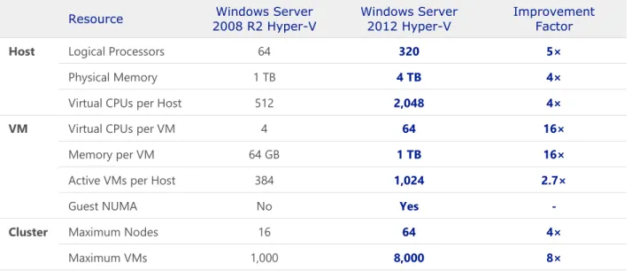
Table 1 highlights additional improvements by comparing the resources supported by Hyper-V in Windows Server 2012 to those supported in Windows Server 2008 R2:8, 9
Table 1: Resources available across versions of Windows Server Syste
m Resource
Windows Server 2008 R2 Hyper-V
Windows Server 2012 Hyper-V
Improvement Factor
Host Logical Processors 64 320 5×
Physical Memory 1 TB 4 TB 4×
Virtual CPUs per Host 512 2,048 4×
VM Virtual CPUs per VM 4 64 16×
Memory per VM 64 GB 1 TB 16×
Active VMs per Host 384 1,024 2.7×
Guest NUMA No Yes
-Cluster Maximum Nodes 16 64 4×
Maximum VMs 1,000 8,000 8×
Significant improvements also have been made within Windows Server 2012 Hyper-V to support increased cluster size and a higher number of active virtual machines per host. Windows Server 2012 Hyper-V supports up to 8,000 virtual machines on a 64-node failover cluster. This is eight times and four times, respectively, the support provided by Windows Server 2008 R2.10 In addition, more advanced
performance features, such as in-guest Non-Uniform Memory Access (NUMA), are supported by Windows Server 2012 Hyper-V virtual machines. Providing these enhancements helps to ensure that customers can achieve the highest levels of scalability, performance, and density for their mission-critical workloads.
Microsoft Assessment and Planning Toolkit
IT infrastructure for server virtualization requires proper planning, which includes gathering details related to the hardware that resides in current environments. The Microsoft Assessment and Planning Toolkit provides server utilization data for Hyper-V server virtualization planning; identifies server placements; and performs virtualization candidate assessments, including return on investment (ROI) analysis for server consolidation with Hyper-V.
Compute Considerations
Organizations need virtualization technology that can support the massive scalability requirements of a demanding Exchange 2013 deployment. One of the key requirements to virtualizing such workloads is to have a large amount of processing and memory power. Therefore, when planning to virtualize mission-critical, high-performance workloads, you must properly plan for these compute resources.
Logical Processors on Hardware
Logical processors are representations or abstractions of a processor’s physical cores themselves or of the number of threads that can be handled by a single physical core of a processor. Windows Server 2012 can run on host servers supporting up to 320 logical processors. With Windows Server 2012, there is no enforced limit on the virtual processor to logical processor (VP:LP) ratio. Users can have as many virtual processors associated with a logical processor as the hardware will allow. However, it is better to test the VP:LP ratio compatibility of the workload that needs to be virtualized to a level where the performance is not adversely affected. For any virtual machine in an Exchange 2013 deployment, we recommend a ratio of 1:1, but a ratio of up to 2:1 is officially supported. Oversubscribing the CPU on the
virtualization host can decrease performance, depending on how much the CPU is oversubscribed. Hyper-V also benefits from larger processor caches, especially for loads that have a large working set in memory and in virtual machine configurations where the VP:LP ratio is high.11
Customers can use processors that support Second Level Address Translation (SLAT) technologies (that is, SLAT-based processors). SLAT technologies add a second level of paging functionality under the paging tables of x86/x64 processors. They provide an indirection layer that maps virtual machine memory addresses to physical memory addresses, which reduces load on the hypervisor for address translation (Figure 2).
SLAT technologies also help to reduce CPU and memory overhead, thereby allowing more virtual machines to be run concurrently on a single Hyper-V machine. The Intel SLAT technology is known as
Extended Page Tables (EPT); the AMD SLAT technology is known as Rapid Virtualization Indexing (RVI), formerly Nested Paging Tables (NPT).
Best Practices and Recommendations
For optimal performance of demanding workloads like Exchange 2013, run Windows Server 2012 Hyper-V on SLAT-capable processors/hardware. This offers the additional benefits of improved performance, greater virtual machine density per host machine, and reduced overhead as compared to non-SLAT systems.
Virtual Processors
A virtual processor or a virtual CPU (vCPU) is a representation of the physical core of a processor or the threads/logical processors in the core. A virtual machine is configured with at least one vCPU that represents time on the physical CPU resource stack. Hyper-V supports configuring virtual machines with more than one virtual processor from multiple physical or logical processors. In other words, one virtual machine can be configured to use multiple physical processor cores at the same time, and this can increase performance in many cases. Such virtual machines are called Symmetric Multi-Processing (SMP) virtual machines. With SMP functionality, applications can benefit from multi-threading while running virtual machines on Hyper-V, thereby enabling workload performance to be optimally distributed as long as enough cores are available. This can be achieved by monitoring the CPU workload on the host. As previously discussed, Windows Server 2012 Hyper-V supports virtual machines with up to 64 virtual processors and 1TB memory. With increased support for 320 logical processors on a host machine, Hyper-V in Windows Server 2012 can now support up to 2,048 virtual processors per host.
Note
Unlike the earlier version of Windows Server, there is no VP:LP ratio imposed by Hyper-V in Windows Server 2012. However, Exchange 2013 supports a VP:LP ratio of no greater than 2:1—and a ratio of 1:1 is recommended.
Windows Server 2012 Hyper-V also provides the Weights and Reserves feature (Figure 3). Weights are assigned to a virtual processor to grant it a larger or smaller share of CPU cycles than the average cycle share. Reserves are set for a virtual processor to ensure that it gets at least a specified percentage of the total possible CPU usage of a virtual machine when there is contention for CPU resources. Simply put, if there is higher demand for CPU than is physically available, Hyper-V ensures that a virtual machine needing CPU resources gets at least its CPU reserve when there is contention.12 This feature is especially
beneficial for system administrators who want to prioritize specific virtual machines depending on the load they have or need to handle.
Figure 3: Weights and reserves in Windows Server 2012
Best Practices and Recommendations
The Weights and Reserves feature, when used properly, can be a great tuning mechanism for Exchange 2013 virtual machines. If CPU resources are overcommitted through other additional workloads, you can set weights and reserves to optimize the way these resources are used so that the Exchange 2013 VMs have priority. Ideally, you should not oversubscribe CPU resources in environments where Exchange 2013 is virtualized.
Non-Uniform Memory Access – Host Perspective
In single system bus architecture, all processors fetch memory from a single pool, and all requests for memory are sent using a single system bus. One problem with this architecture is that as the speed and number of processors increase, it becomes difficult for the system to handle a large number of memory requests. This leads to issues such as memory latency and scalability limitations. While one solution for such issues is to have larger cache size, this helps only to a certain extent. The issues related to memory access can be best resolved with NUMA.13
NUMA is a memory design architecture that delivers significant advantages over the single system bus architecture and provides a scalable solution to memory access problems. In a NUMA-supported operating system, CPUs are arranged in smaller systems called nodes (Figure 4). Each node has its own processors and memory, and is connected to the larger system through a cache-coherent interconnect bus.14
Figure 4: NUMA node (processor and memory grouped together)
Multiple NUMA nodes can exist in a host system (Figure 5). In the context of multiple nodes:
Local memory is attached directly to the processor (grouped into a node).
Remote memory is local to another processor in the system (another node).
This grouping into nodes reduces the time required by a processor to access memory (locally located), as the processor can access local memory faster than remote memory.15
Figure 5: Multiple NUMA nodes on a single host
Root/Host Reserve
Root reserve or host reserve is the amount of memory that is reserved for the root partition and is guaranteed to be available to the root partition. It is not allocated to any of the virtual machines running in the child partition. Hyper-V automatically calculates root reserve based on the physical memory available on the host system and system architecture.16
Best Practices and Recommendations
The root partition must have sufficient memory to provide services such as I/O virtualization, virtual machine snapshot, and management to support the child partitions. Hyper-V calculates an amount of memory (known as the root reserve), which is guaranteed to be available to the root partition. This memory is never assigned to virtual machines. Root reserve is calculated
Page File Guidance
When a machine runs low on memory and needs more immediately, the operating system uses hard disk space to supplement system RAM through a procedure called paging. Too much paging degrades overall system performance. However, you can optimize paging by using the following best practices and recommendations for page file placement.
Best Practices and Recommendations
Let the Windows Server 2012 Hyper-V host operating system handle the page file sizing. It is well optimized in this release.
Isolate the page file on its own storage devices, or at least make sure it does not share the same storage devices as other frequently accessed files. For example, place the page file and operating system files on separate physical disk drives.
Place the page file on a drive that is not fault-tolerant. Note that if the disk fails, a system crash is likely to occur. If you place the page file on a fault-tolerant drive, remember that fault-tolerant systems are often slower to write data because they do so to multiple locations.
Use multiple disks or a disk array if you need additional disk bandwidth for paging. Do not place multiple page files on different partitions of the same physical disk drive.
The following additional best practices and recommendations should be considered while planning and managing host compute (CPU and memory) resources.17
Best Practices and Recommendations
While performing capacity planning for virtualizing workloads, always count the number of cores required and not the number of logical processors/threads required.
Note: Dynamic Memory is not supported for Exchange 2013 and is not NUMA-aware. When you are planning how to use the host server’s memory, it is important to consider the
virtualization-related overhead. Whether you choose to use NUMA and/or Dynamic Memory, both have some overhead related to memory management in the virtualized environment. There may be scenarios when using NUMA and/or Dynamic Memory may not be the best option. For Exchange Server, memory allocations must be statically configured. Properly plan the memory requirements for running Exchange 2013 workloads on Windows Server 2012, and do not use Dynamic Memory for Exchange 2013 virtual machines. (For more information, see our NUMA best practices and recommendations).
There is an additional load on root server processors because the root servers manage running guest machines. This overhead varies in different scenarios; however, it is good to consider some
Storage Considerations
Storage configuration is one of the critical design considerations for any Mailbox Server role in Exchange 2013. With a growing number of physical storage devices resulting in increased power use, organizations want to reduce energy consumption and hardware maintenance costs through virtualization. Running Exchange 2013 on hardware that is either underutilized or oversubscribed increases overall operational costs, including the cost of providing power, cooling, and storage infrastructure, as well as the
administrative overhead of maintaining storage capacity on this hardware.
Windows Server 2012 Hyper-V has a number of different storage options for storing the virtual disks and related data associated with a virtualized Exchange 2013 infrastructure, providing the administrator with flexibility to choose based on desired levels of performance, resiliency, and budget.
Storage Options for Hyper-V Virtual Machines
Storage virtualization helps administrators perform backup, archiving, and recovery tasks by reducing the complexity of storage devices and the time required to manage them. Windows Server 2012 introduces a class of sophisticated storage virtualization enhancements that can be easily implemented to develop resilient infrastructure. These enhancements use two new concepts: Storage Spaces and Storage Pools.
Storage Spaces
With the Storage Spaces technology, you can achieve a desired level of resiliency through automatic or controlled allocation of heterogeneous storage media presented as one logical entity. Storage Spaces shields the physical disks and presents selected storage capacity as pools, known as storage pools, in which a virtual disk, known as a storage space, can be created. Storage Spaces supports two optional resiliency modes: mirror and parity. These provide per-pool support for disks that are reserved for replacing failed disks (hot spares), background scrubbing, and intelligent error correction. In case of a power failure or cluster failover, the integrity of data is preserved so that recovery happens quickly and does not result in data loss.
The Storage Spaces technology is fully integrated with failover clustering to enable continuously available service deployments. One or more storage pools can be clustered across multiple nodes within a single cluster. Storage Spaces supports thin provisioning to allow organizations to easily share storage capacity among multiple unrelated data sets, thereby maximizing capacity use. Fully scriptable management is enabled through the Windows Storage Management API, Windows Management Instrumentation (WMI), and Windows PowerShell. Storage Spaces also can be managed through the File and Storage Services role in Server Manager. Finally, Storage Spaces provides notifications when the amount of available capacity in a storage pool hits a configurable threshold.
Storage Pools
Storage pools are a collection of disks used for storing replicas, shadow copies, and transfer logs and are the fundamental building blocks for Storage Spaces (Figure 6). In Windows Server 2012, storage pools are a collection of physical disks grouped together into one or more containers. This allows for storage aggregation, flexible capacity expansion, and delegated administration of storage. Windows Server 2012 maps a storage pool by combining a group of hard disks and/or solid-state drives (SSDs). By simply adding additional drives, storage pools are dynamically expanded to handle the growing size of data.
Thinly provisioned virtual disks can be provisioned from the available capacity. Thin provisioning helps to reserve the actual capacity by reclaiming capacity on the space when files are deleted or no longer in use. Figure 6: Conceptual deployment model for storage spaces and storage pools
Types of Storage Spaces
There are three key types of storage spaces: simple/striped spaces, mirror spaces, and parity spaces. Each is discussed in more detail below.19
Simple spaces/striped spaces: Simple storage spaces are used for storing temporary data because they are non-resilient to disk failures. Striping is the process of writing data across multiple disks to reduce access and response times. Logical blocks of data with a defined size are laid out in a sequential circular manner across multiple disks. This helps in balancing the storage load across all physical drives. Striping provides the overall best performance in terms of reads and writes but, as noted, provides no resiliency. In Figure 7, there are four disks, and 1 MB of data needs to be written to these disks. In this case, there are two options for writing data to the disks: Either write all of the data to a single disk and access it from there, or write 256 KB to each of the four disks simultaneously. The second option results in a quadruple decrease in write times.20 The greater the number of disks Storage Spaces can stripe across, the better the
performance will be.
Striped storage spaces can be used for the following:
Delivering the overall best performance in terms of reads and writes.
Balancing the overall storage load across all physical drives.
Backing up disks to increase backup throughput or to distribute the use of space across disks. Mirror spaces: This data layout process uses the concept of mirroring to create copies of data on multiple physical disks. A logical virtual disk is created by combining two or more sets of mirrored disks. Mirror storage spaces are resilient in nature because in the event of failure, if one copy is lost, the other is still available. To make them resilient from disk failures, mirror spaces are configured to at least one (two-way mirror) or two (three-way mirror) concurrent physical disks.
In Figure 8, 512 KB of data needs to be written to the storage space. For the first stripe of data (A1), Storage Spaces writes 256 KB of data to the first column, which is written in duplicate to the first two disks. For the second stripe of data (A2), Storage Spaces writes 256 KB of data to the second column, which is written in duplicate to the next two disks. The column-to-disk correlation of a two-way mirror is 1:2, while for a three-way mirror, the correlation is 1:3. Reads on mirror spaces are very fast because they are done from either of the two copies of data. If disks 1 and 3 are busy servicing another request, the needed data can be read from disks 2 and 4.
Figure 8: Mirror storage space across four disks
Mirror storage spaces are used for the following:
Enabling faster reads on data.
Increasing resiliency and protection from disk failures.
Parity spaces: Parity storage spaces store parity-bit information that helps in reconstructing data from a failed disk. This can be useful in providing data recovery capabilities. Storage Spaces uses rotating parity that stores data and parity information by rotating from stripe to stripe across different disks. Parity spaces tend to have lower write performance than mirror spaces because each parity block takes time in updating itself to the corresponding modified data block. Parity is more cost efficient than mirroring because it requires only one additional disk per virtual disk, instead of double or triple the total number of disks in an array.
In Figure 9, for the first stripe of data, 768 KB is written across disks 1 through 3 (A1, A2, A3), while the corresponding parity bit (AP) is placed on disk 4. For the second stripe of data, Storage Spaces writes the data on disks 1, 2, and 4, thereby rotating the parity to disk 3 (BP). Because parity is striped across all disks, it provides good read performance and resiliency to single disk failure.
Figure 9: Parity storage space across four disks
Parity storage spaces are used for the following:
Providing data recovery of failed disks.
Offering efficient capacity utilization.
Delivering faster read operations.
Providing bulk backups by writing data in large sequential append blocks.
The graphs in Figure 10 show the performance scaling of a simple storage space with up to 32 disks, which resulted in a random read 1.4 million IOPS and 10.9 GB/sec of sequential throughput.21
Figure 10: Performance scaling of a simple storage space
Storage Protocols and Additional Features
Various storage protocols can help in virtualizing workloads to connect easily and reliably to existing storage arrays. These storage protocols include a vast number of storage feature enhancements that increase administrative flexibility, efficiency, and control by centralizing management of storage volumes. Apart from storage protocols, Windows Server 2012 allows efficient data movement using intelligent storage arrays and enables rapid provisioning and migration of virtual machines. Some of these storage protocols and features are described below.
Server Message Block 3.0
The Server Message Block (SMB) protocol is a network file sharing protocol that allows applications to read, create, update, and access files or other resources at a remote server. The SMB protocol can be used on top of its TCP/IP protocol or other network protocols. Windows Server 2012 introduces the new 3.0 version of the SMB protocol that greatly enhances the reliability, availability, manageability, and
performance of file servers. SMB 3.0 also allows you to create a failover cluster without shared storage or expensive storage area networks (SANs).
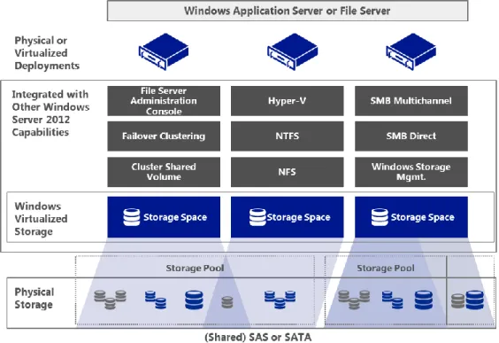
Hyper-V over SMB
By enabling Hyper-V to use SMB file shares, you can greatly enhance performance with easy and inexpensive deployments of virtual storage. Hyper-V over SMB can be used to keep virtual storage (.vhd and .vhdx files) on a remote file server rather than requiring the Hyper-V host to manage the storage for its many virtual machines. This allows Hyper-V hosts to provide compute resources with many processors and RAM while using virtual storage resources provided by file servers. Hyper-V over SMB requires:
One or more computers running Windows Server 2012 with the Hyper-V and File and Storage Services roles installed.
A common Active Directory infrastructure. (The servers running Active Directory Domain Services do not have to run Windows Server 2012.)
Note that failover clustering on the Hyper-V side, the File and Storage Services side, or both is optional. Hyper-V over SMB supports a variety of flexible configurations that offer different levels of capabilities and availability. These configurations include Single-Node File Server, Dual-Node File Server, and Multi-Node File Server, as shown in the following figures.22
Single-Node File Server: In a Single-Node File Server, Hyper-V shares are used for VHD storage (Figure 11). File servers use standalone and local storage. This configuration provides flexibility for shared storage, as well as low costs for acquisition and operation. It does not provide continuous availability. Storage is not fault-tolerant, and Hyper-V virtual machines are not highly available.
Dual-Node File Server: In a Dual-Node File Server, file servers can be clustered storage spaces, where shares are used for VHD storage (Figure 12). This configuration provides flexibility for shared storage, fault-tolerant storage, and low costs for acquisition and operation. It also offers continuous availability but with limited scalability.
Figure 12: Dual-Node File Server
Multi-Node File Server: A Multi-Node File Server uses clustered Hyper-V file servers and storage spaces, where shares are used for VHD storage (Figure 13). This configuration provides flexibility for shared storage, fault-tolerant storage, and low costs for acquisition and operation. It also provides continuous availability, and Hyper-V virtual machines are highly available.
Figure 13: Multi-Node File Server
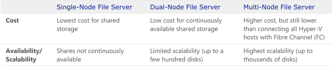
Table 2 compares the cost and availability/scalability of the three configurations for Hyper-V over SMB. Table 2: Comparison of Hyper-V over SMB configurations
Single-Node File Server Dual-Node File Server Multi-Node File Server
Cost Lowest cost for shared storage
Low cost for continuously available shared storage
Higher cost, but still lower than connecting all Hyper-V hosts with Fibre Channel (FC)
Best Practices and Recommendations
Fixed of dynamic virtual disks may be stored on SMB 3.0 files that are backed by block-level storage if the guest machine is running on Windows Server 2012 Hyper-V (or a later version of Hyper-V). The only supported usage of SMB 3.0 file shares is for storage of fixed or dynamic virtual disks. Such file shares cannot be used for direct storage of Exchange data. When using SMB 3.0 file shares to store fixed or dynamic virtual disks, configure the storage backing the file share for high availability to ensure the best possible availability of the Exchange virtual machines.
SMB Multichannel
Both the SMB client and SMB server must support SMB 3.0 to take advantage of the SMB Multichannel functionality. SMB Multichannel increases network performance and availability for file servers. SMB Multichannel allows file servers to use multiple network connections simultaneously. This increases throughput by transmitting more data using multiple connections for high-speed network adapters or multiple network adapters. When using multiple network connections at the same time, the clients can continue to work uninterrupted despite the loss of a network connection. SMB Multichannel automatically discovers the existence of multiple available network paths and dynamically adds connections as required.
Best Practices and Recommendations
If you use SMB storage with Hyper-V, use multiple network adapters to take advantage of SMB Multichannel, as this provides increased performance and resiliency.
SMB Direct (SMB over RDMA)
Windows Server 2012 introduces SMB Direct, a feature that provides the ability to use Remote Direct Memory Access (RDMA) network interfaces for high throughput with low latency and CPU utilization. SMB Direct supports the use of network adapters that have RDMA capability. Network adapters with RDMA can function at full speed with very low latency, while using very little CPU. For workloads such as Hyper-V or Exchange Server, this enables a remote file server to resemble local storage. SMB Direct is automatically configured by Windows Server 2012 and includes the following benefits:
Increased throughput: Takes advantage of the full throughput of high-speed networks where the network adapters coordinate the transfer of large amounts of data at line speed.
Low latency: Provides extremely fast responses to network requests and, as a result, makes remote file storage feel as if it is directly attached block storage.
Low CPU utilization: Uses fewer CPU cycles when transferring data over the network, which leaves more power available to server applications.
By supporting mission-critical application workloads, the new SMB server and client cooperate to provide transparent failover to an alternative cluster node for all SMB operations for planned moves and
unplanned failures. This results in reduced cost, improved high availability, and increased performance for workloads in a virtualized environment.
Best Practices and Recommendations
SMB Direct works with SMB Multichannel to transparently provide exceptional performance and failover resiliency when multiple RDMA links between clients and SMB file servers are detected. Also, because RDMA bypasses the kernel stack, it does not work with Network Interface Card (NIC) Teaming, but does work with SMB Multichannel (because SMB Multichannel is enabled at the application layer).
Customers with existing investments in enterprise-class storage arrays that support the SMB 3.0 protocol can connect these arrays directly to the Hyper-V hosts and use them to store the virtual disks (and data) of key applications and workloads.
Loopback configurations are not supported by Hyper-V when the file server is configured on the host where the virtual machines are running.
The ESG Lab tested the SMB 3.0 protocol by using an online transaction processing (OLTP) workload application to simulate the activity of SQL Server users (Figure 14).23 The goal was to demonstrate the
performance, scalability, and efficiency of the SMB protocol, Hyper-V hypervisor, and SQL Server database engine on cost-effective commodity hardware.
A database of 3,000 customers was configured within each of eight SQL Server virtual machines, with a goal of achieving linear scalability for the number of transactions per second as the number of
consolidated SQL Server virtual machines increased. The transactions per second and average response time were monitored as the number of customers and virtual machines increased.
Figure 14: Workload scalability with SMB 3.0 and SQL Server
As shown in the graph, as the number of Hyper-V virtual machines increased, the number of transactions per second increased, while recorded average transaction response times were manageably low—even though the virtual machines and respective databases resided on remote file servers accessed using SMB 3.0. The full report and further details are available here.
Internet SCSI
The Internet Small Computer System Interface (iSCSI) protocol is based on a storage networking standard that facilitates data transfers over the Internet and manages storage over long distances, all while
enabling hosts to operate as if the disks were attached locally.
An iSCSI target is available as a built-in option in Windows Server 2012; it allows sharing block storage remotely by using the Ethernet network without any specialized hardware. It also provides support for diskless network boot capabilities and continuous availability configurations.
Fibre Channel
Fibre Channel (FC) is a data transmitting technology that enables server-to-storage connectivity at 16 GB and is well suited for connecting storage controllers and drives. Fibre Channel offers point-to-point, switched, and loop interfaces. It is designed to interoperate with SCSI, the Internet Protocol (IP), and other protocols. With the new 16 GB FC, a bi-directional throughput of 3,200 MB/sec can deliver over 1 million IOPS. This enhancement supports deployments of densely virtualized servers, increases scalability, and matches the performance of multicore processors and SSD-based storage infrastructure. 16 GB FC is backward compatible with 8/4 GB FC, allowing them to be seamlessly integrated into expansion segments of existing FC networks.
Windows Server 2012 fully supports FC connectivity for storage of virtual machine files. In addition, Windows Server 2012 Hyper-V provides a new capability for the virtual machines themselves, known as
Hyper-V Virtual Fibre Channel (VFC). This capability enables connecting to FC storage directly from within virtual machines, opening up new scenarios around guest clustering and providing a more direct path to the underlying FC fabric from within the virtual infrastructure.
Fibre Channel over Ethernet
Fibre Channel over Ethernet (FCoE) offers the benefits of using an Ethernet transport while retaining the advantages of the FC protocol and the ability to use FC storage arrays. This solution helps to reduce costs in several ways, including the elimination of dedicated FC switches and a reduction in cabling (which can be a significant cost in large data center environments). For higher performance and availability, FCoE provides direct connections to the FC host bus adapter (HBA) and SAN fabric from Hyper-V virtual machines.
Best Practices and Recommendations
Some of the vendors supporting FCoE hardware include NetApp, Brocade, Cisco, Intel, QLogic, EMC, and Emulex.
FCoE requires switches that have Data Center Bridging (DCB), which provides the extensions to traditional Ethernet that make it suitable for transporting storage traffic in a lossless way. The DCB capability is available in some 10 GbE switches. Adapters that work with FCoE are known as
converged network adapters (CNAs). Traditional Ethernet and FC host bus adapter (HBA) vendors provide CNAs and support Ethernet and FC simultaneously over the same wire. These CNAs run at 10 Gbps for both Ethernet and FC.
Best Practices and Recommendations
Standard 10/100, 1 Gb, or 10 GbE do not support FCoE. FCoE runs on versions of Ethernet that have been improved to provide low latency, quality of service, guaranteed delivery, and other functionality traditionally associated with channel interfaces.
Fibre Channel, OM3, and OM4 cabling are suitable for FCoE and 10 GbE.
Multipath I/O
Microsoft Multipath I/O (MPIO) is a framework provided by Microsoft for developing multipath solutions that contain hardware-specific information required to enhance connectivity for storage arrays. In other words, MPIO increases the availability of storage resources by providing support for using multiple data paths to a storage device. MPIO uses host-based software, called device-specific modules (DSMs), to provide this multipath support. MPIO is protocol-independent and can be used with FC, iSCSI, and Serial Attached SCSI (SAS) interfaces in Windows Server 2012. MPIO in Windows Server 2012 provides the following enhanced features:
PowerShell management and configuration: MPIO can be configured using PowerShell as an alternative to MPCLAIM.exe.
Heterogeneous HBA usage with MPIO: Heterogeneous HBA types now can be used together with non-boot virtual disks only.
Support for MPIO with multiport-SAS enclosures: The use of MPIO with data volumes on a multiport-SAS enclosure is now supported.
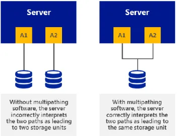
An MPIO/multipath driver cannot work effectively until it discovers, enumerates, and configures into a logical group the different devices that the operating system sees through redundant adapters. Figure 15 shows that without any multipath driver, the same devices through different physical paths would appear as different devices, leaving room for data corruption.
With MPIO, Windows Server 2012 efficiently manages up to 32 paths between storage devices and the Windows host operating system, and provides fault-tolerant connectivity to storage. Further, as more data is consolidated on SANs, the potential loss of access to storage resources is unacceptable. To mitigate this risk, high availability solutions like MPIO have become a requirement.
MPIO provides the logical facility for routing I/O over redundant hardware paths connecting servers to storage. These redundant hardware paths are composed of components such as cabling, HBAs, switches, storage controllers, and possibly even power. MPIO solutions logically manage these redundant
connections so that I/O requests can be rerouted if a component along one path fails. The MPIO software supports the ability to balance I/O workloads without administrator intervention. MPIO determines which paths to a device are in an active state and can be used for load balancing. Each vendor’s load balancing policy setting is set in the DSM. (Individual policy settings may use any of several algorithms—such as Round Robin, Least Queue Depth, Weighted Path, and Least Blocks—or a vendor-unique algorithm.) This policy setting determines how I/O requests are actually routed.
Best Practices and Recommendations
To determine which DSM to use with existing storage, it is important to check with the storage array manufacturer. Multipath solutions are supported as long as a DSM is implemented in line with logo requirements for MPIO. Most multipath solutions for Windows use the MPIO architecture and a DSM provided by the storage array manufacturer. Use the Microsoft DSM provided in Windows Server only if it is also supported by the storage array manufacturer, in lieu of the manufacturer providing its own DSM.
A DSM from the storage array manufacturer may provide additional value beyond the
implementation of the Microsoft DSM because the software typically provides auto-configuration, heuristics for specific storage arrays, statistical analysis, and integrated management. We
recommend that you use the DSM provided by the storage array manufacturer to achieve optimal performance. This is because storage array manufacturers can make more advanced path decisions in their DSMs that are specific to their arrays, which may result in quicker path failover times.
Offloaded Data Transfer
Offloaded Data Transfer (ODX) in Windows Server 2012 enables customers who have invested in storage technologies such as iSCSI or FC SANs to accomplish more with existing external storage arrays. This is because ODX lets you quickly move large files and virtual machines directly between storage arrays, which reduces host CPU and network resource consumption.
ODX enables rapid provisioning and migration of virtual machines and provides significantly faster transfers of large files, such as database or video files. By offloading the file transfer to the storage array, ODX minimizes latencies; maximizes the use of array throughput; and reduces host resource usage, such as CPU and network consumption. File transfers are automatically and transparently offloaded when you move or copy files, regardless of whether you perform drag-and-drop operations in Windows Explorer or use command-line file copy commands. No administrator setup or intervention is needed.
To eliminate the inefficient and unnecessary steps required by traditional host-based file transfers, ODX uses a token-based mechanism for reading and writing data within or between intelligent virtual storage database volumes (Figure 16). Instead of routing the data through the host, a small token is copied between the source and destination. The token serves as a point-in-time representation of the data. For example, when you copy a file or migrate a virtual machine between storage locations, Windows Server 2012 copies the token representing the virtual machine file. This removes the need to copy the underlying data between servers.
Figure 16: Offloaded Data Transfer in Windows Server 2012
The ESG Lab tested the efficiency and functionality of Offloaded Data Transfer. Two servers were connected to an ODX-compliant Dell EqualLogic storage array.24 The storage array consisted of 12 SAS
drives (600 GB each). A single RAID5 pool was created with two volumes: One contained a 75 GB virtual machine, and the other was empty. Using an intuitive wizard, the ESG Lab configured a virtual machine live migration from one server to another within a SAN. The lab specified the type of move, the server receiving the data, move options, and destination virtual machine options. It then transferred a virtual machine using the traditional non-ODX method and the new ODX method. The lab monitored network utilization and elapsed time for the transfer to complete in both test cases.
The results in Figure 17 show noticeable improvements using ODX. The ODX transfer took approximately 6.5 minutes for the virtual machine to completely migrate to the other server, and the average network bandwidth consumption was around 64 Kb/sec. Conversely, with non-ODX method, moving the 75 GB virtual machine over the network took approximately 52 minutes and consumed 4 Mb/sec of network bandwidth. The ODX method completed eight times faster than the non-ODX method, while consuming virtually no server CPU or network resources.
Figure 17: Faster SAN-attached virtual machine migrations with ODX
Best Practices and Recommendations
If you are using SAS or FC in all clustered servers, all elements of the storage stack should be identical. It is required that the MPIO and DSM software be identical. It is recommended that the mass storage device controllers (that is, the HBA, HBA drivers, and HBA firmware attached to cluster storage) be identical.25
If you are using iSCSI, each clustered server should have a minimum of two network adapters or iSCSI HBAs that are dedicated to the cluster storage. The network being used for iSCSI should not be used for network communication. In all clustered servers, the network adapters being used to connect to the iSCSI storage target should be identical, and we recommend that you use Gigabit Ethernet or higher. Network adapter teaming (also called load balancing and failover, or LBFO) is not supported for iSCSI. MPIO software should be used instead.
ODX is enabled by default, but check with your storage vendor for support, as upgraded firmware may be required.
Networking Considerations
Networking in a virtualized Exchange environment is a critical component for managing traffic in an optimal way. The appropriately architected network seamlessly routes people to their mailboxes while maintaining a consistent end-user experience. Network performance and availability are essential for mission-critical applications like Exchange 2013.
Windows Server 2008 R2 introduced several networking-related features that help to reduce networking complexity while simplifying management tasks. Windows Server 2012 improves on this functionality in several ways, including new and enhanced features for NIC Teaming, the Hyper-V Extensible Switch, virtual LANs (VLANs), and Virtual Machine Queue (VMQ).
Host Resiliency with NIC Teaming
NIC Teaming gives the ability to bond multiple high-speed network interfaces together into one logical NIC to support workload applications that require heavy network I/O and redundancy (Figure 18). Windows Server 2012 offers fault tolerance of network adapters with inbox NIC Teaming. This provides advanced networking capabilities to aggregate bandwidth from multiple network adapters and traffic failovers to prevent connectivity loss (so that failure of one NIC within the team does not affect the availability of the workload).
Figure 18: NIC Teaming in a virtual machine configuration
The built-in NIC Teaming solution in Windows Server 2012:
Works with all network adapter vendors.
Eliminates potential problems caused by proprietary solutions.
Provides a common set of management tools for all adapter types.
Is supported by Microsoft.
The solution also works within a virtual machine hosted on Hyper-V by allowing virtual network adapters to connect to more than one Hyper-V switch and still have connectivity even if the NIC underlying a certain switch gets disconnected. NIC Teaming uses two basic sets of configuration algorithms to provide better flexibility when designing networking for complex scenarios: dependent mode and switch-independent mode.
Switch-dependent mode: These algorithms require all the network adapters of the team to be connected to the same switch. Two common ways in which the switch-dependent mode can be configured are as follows:
Generic, or static, teaming (IEEE 802.3ad draft v1) requires configuration on the switch and computer to identify which links form the team.
Dynamic teaming (IEEE 802.1ax, LACP) uses the Link Aggregation Control Protocol (LACP) to dynamically identify links between the computer and a specific switch.
Switch-independent mode: These algorithms do not require the switch to participate in the teaming. The team network adapters can be connected to different switches because a switch does not know to which
Best Practices and Recommendations
We recommend that you use host-level NIC Teaming to increase resiliency and bandwidth. NIC Teaming supports up to 32 NICs from mixed vendors. It is important to have NICs within a team with the same speed.
Hyper-V Extensible Switch
Shown in Figure 19, the Hyper-V Extensible Switch is a layer-2 virtual interface that provides programmatically managed and extensible capabilities to connect virtual machines to the physical
network.26 With its new features and enhanced capabilities, the Hyper-V Extensible Switch supports tenant
isolation, traffic shaping, protection against virtual machines infected with malicious code, and simplified troubleshooting. With built-in support for Network Device Interface Specification (NDIS) filter drivers and Windows Filtering Platform (WFP) callout drivers, the Hyper-V Extensible Switch also enables independent software vendors (ISVs) to create extensible plug-ins (known as Virtual Switch Extensions) that can provide enhanced networking and security capabilities.
Figure 19: Hyper-V Extensible Switch
The two public Windows platforms for extending Windows networking functionality are used as follows:
NDIS filter drivers: Used to monitor or modify network packets in Windows.
WFP callout drivers: Used to allow ISVs to create drivers to filter and modify TCP/IP packets, monitor or authorize connections, filter IPsec-protected traffic, and filter RPCs. Filtering and
In this path, the outgoing and incoming packets can be modified or examined before additional processing occurs. By accessing the TCP/IP processing path at different layers, ISVs can easily create firewalls, antivirus software, diagnostic software, and other types of applications and services.
Extensions can extend or replace the following three aspects of the switching process: ingress filtering, destination lookup and forwarding, and egress filtering. Table 3 lists a number of top partners that offer networking extensions for Hyper-V environments, as well as their key extension products.
Table 3: Example options for networking extensions
Cisco Nexus® 1000V Series Switches and Cisco Unified
Computing System™ Virtual Machine Fabric Extender (VM-FEX) NEC ProgrammableFlow PF1000
InMon sFlow Agent
5nine Security Manager for Hyper-V
Virtual LANs
Virtual LANs (VLANs) subdivide a network into logical groups that share common physical infrastructure to provide network isolation. A VLAN uses explicit tagging in the Ethernet frames, and relies on Ethernet switches to enforce isolation and restrict traffic to network nodes of the same tag. However, there are some drawbacks with VLANs that limit networking capabilities within a large and complex network that provides communications for mission-critical workloads.
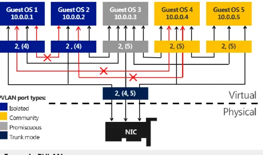
Windows Server 2012 introduces support for private VLANs (PVLANs) that extends the VLAN capabilities by providing isolation between two virtual machines on the same VLAN. Network virtualization in Windows Server 2012 removes the constraints of VLAN and hierarchical IP address assignment for virtual machine provisioning. Windows Server 2012 PVLANs provide scalability and better isolation of workloads. With PVLANs, a VLAN domain can be divided into subdomains that are represented by a pair of VLANs (primary VLAN and secondary VLAN). In such an implementation, every virtual machine in a PVLAN is assigned one primary VLAN ID and one or more secondary VLAN IDs. There are three modes for secondary PVLANs (Figure 20):
Isolated: Isolated ports cannot exchange packets with each other at layer 2. If fact, isolated ports can only talk to promiscuous ports.
Community: Community ports on the same VLAN ID can exchange packets with each other at layer 2. They can also talk to promiscuous ports. They cannot talk to isolated ports.
Promiscuous: Promiscuous ports can exchange packets with any other port on the same primary VLAN ID (secondary VLAN ID makes no difference).
Figure 20: PVLAN in Windows Server 2012
Best Practices and Recommendations
VLANS and PVLANS can be a useful mechanism to isolate different Exchange infrastructures—for instance, a service provider hosting multiple unrelated Exchange infrastructures. For customers with VLAN constraints, PVLANS enable extra levels of isolation granularity within the same VLAN. PVLANS can be configured through PowerShell.
Hardware Offloads – Dynamic Virtual Machine Queue
Virtual Machine Queue (VMQ) allows the host’s network adapter to pass DMA packets directly into individual virtual machine memory stacks. Each virtual machine device buffer is assigned a VMQ, which avoids needless packet copies and route lookups in the virtual switch. Essentially, VMQ allows the host’s single network adapter to appear as multiple network adapters to the virtual machines, allowing each virtual machine its own dedicated network adapter. The result is less data in the host’s buffers and an overall performance improvement to I/O operations.
VMQ is a hardware virtualization technology for the efficient transfer of network traffic to a virtualized host operating system. A VMQ-capable network adapter classifies incoming frames to be routed to a receive queue based on filters that associate the queue with a virtual machine’s virtual network adapter. These hardware queues may be affinitized to different CPUs, thereby enabling receive scaling on a per-virtual network adapter basis.
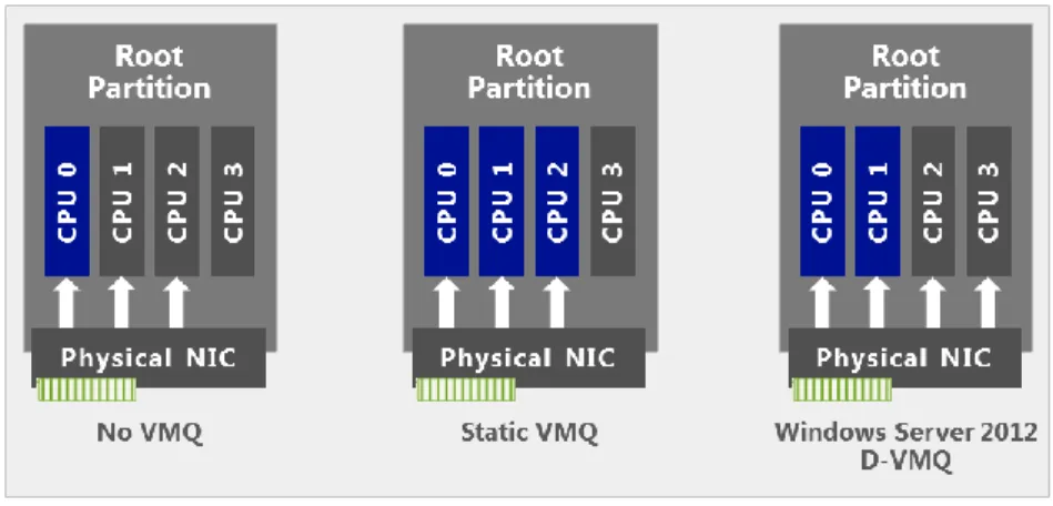
Windows Server 2008 R2 allowed administrators to statically configure the number of processors available to process interrupts for VMQ. Without VMQ, CPU 0 would run hot with increased network traffic. With
VMQ, the interrupts were spread across more processors. However, network load could vary over time. A fixed number of processors may not have be suitable in all traffic regimes.
Windows Server 2012, on the other hand, dynamically distributes the processing of incoming network traffic to host processors, based on processor use and network load. In times of heavy network load, Dynamic VMQ (D-VMQ) automatically uses more processors. In times of light network load, D-VMQ relinquishes those same processors. This helps to ensure that overall performance is optimized.
As shown in Figure 21, without the VMQ technology and RSS, the majority of network processing burdens CPU 0 and ultimately limits the scale of the solution. With D-VMQ, processor cores are dynamically assigned to distribute the workload.
Figure 21: Dynamically distributed workload with D-VMQ for Hyper-V
Best Practices and Recommendations
Some Intel multicore processors may use Intel Threading Technology. When Hyper-Threading Technology is enabled, the actual number of cores that are used by D-VMQ should be half the total number of logical processors that are available in the system. This is because D-VMQ spreads the processing across individual physical cores only, and it does not use hyper-threaded sibling cores.
As an example, if the machine has an Intel processor with four physical cores and Hyper-Threading Technology is enabled, it will show a total of eight logical processors. However, only four logical processors are available to VMQ. (VMQ will use cores 0, 2, 4, and 6.)
VMQ provides improved networking performance for the management operating system as a whole rather than for a specific virtual machine. For best results, treat queues as a scarce, carefully managed resource. Because queues are allocated to virtual machines on a first-come, first-served basis, making all virtual machines eligible for a queue may result in some queues being given to virtual machines with light traffic instead of those with heavier traffic. Enable VMQ only for those virtual machines with the heaviest inbound traffic. Because VMQ primarily improves receive-side performance, providing queues for virtual machines that receive the most packets
Host Resiliency & VM Agility
For mission-critical workloads, high availability and scalability are becoming increasingly important to ensure that all users can access data and applications whenever they want. Windows Server 2012 Hyper-V provides enhanced capabilities that help to ensure that Exchange 2013 workloads are agile, easy to manage, and highly available at the hypervisor level.
Host Clustering
This subsection discusses the key elements of host clustering, including failover clustering, Cluster Shared Volumes, cluster networking, cluster-aware updating, virtual machine priority, virtual machine affinity, and live migration.
Failover Clustering
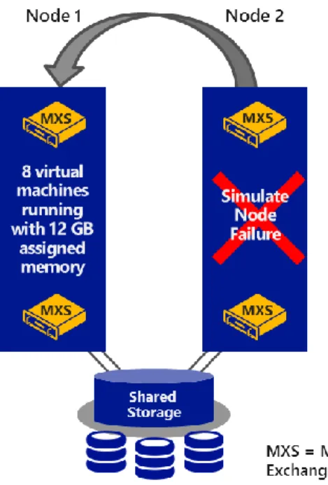
Failover clustering allows you to connect physical machines (also called nodes) together to provide better scalability and high availability. These clustered nodes work in such a way that if one or more of the active nodes fail, the other nodes in the cluster begin to provide service (Figure 22). Clustered nodes are
continuously monitored to ensure that they are working properly. The nodes come to know each other’s active status by using a heartbeat—a periodic signal between two directly connected machines.
Best Practices and Recommendations
All hardware should be certified for Windows Server 2012, and the failover cluster solution should pass all tests in the Validate a Configuration Wizard. For more information about validating a failover cluster, see Validate Hardware for a Windows Server 2012 Failover Cluster.
Windows Server 2012 Hyper-V supports scaling clusters up to 64 nodes and 8,000 virtual machines per cluster. Windows Server 2012 also provides Windows PowerShell cmdlets and a snap-in for Failover Cluster Manager, which allows administrators to manage multiple clustered nodes.
The aim of failover clustering is to provide a resilient solution for workloads that are running on top of the cluster. These could be clustered roles such as a file server, a DHCP server, or (as in the case of this paper) a virtual machine. The Windows Server 2012 Failover Clustering capability provides resiliency for a number of other roles or services. Additional information about this capability can be found here.
With virtual machines running on top of a Hyper-V cluster, should a Hyper-V cluster node fail, the virtual machines also will experience downtime. However, the remaining cluster nodes immediately start working to bring those virtual machines up again on an alternative node within the cluster—helping to ensure that downtime is minimal and that administrator intervention is not required. This means that the workload— in this case, Exchange 2013—has an extra level of resiliency when compared to a physical implementation. The physical implementation requires the administrator to rely on only application-level resiliency, as opposed to the dual layers of resiliency provided by a clustered Hyper-V implementation. This topic is explored in more detail later in this paper.
Cluster Shared Volumes
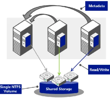
With Cluster Shared Volumes (CSV), Windows Server 2012 provides shared storage resources for clustered virtual machines. The CSV technology makes it easy to manage large numbers of LUNs in a failover cluster. CSV allows simultaneous read-write permissions to the same NTFS-provisioned LUN disk from multiple cluster nodes (Figure 23). Due to significant improvements in the CSV design in Windows Server 2012, Cluster Shared Volumes can perform an increased number of operations in direct I/O mode as compared to previous versions of Windows Server. This feature also can be helpful while operating workloads for failover, conducting live migration, or moving workloads. It allows workloads to share the same volume without impacting the other workloads.
CSV provides better security for mission-critical data by supporting BitLocker Drive Encryption.
For decrypting data, CSV uses cluster name objects as identity for data decryption.
CSV provides continuous availability and scalability of file-based server storage for applications or databases using the Scale-Out File Server feature.
CSV supports two types of snapshots, including application-consistent and crash-consistent Volume Shadow Copy Service (VSS) snapshots.