Engine Quick Start Guide
For the CoreBuilder
®9000 Enterprise Switch
Module Description
The 3Com CoreBuilder
®9000 Enterprise Management Engine (EME) is an
SNMP-based network management module that enables you to
configure and manage the 3Com CoreBuilder 9000 7-slot chassis, 8-slot
chassis, and 16-slot chassis, and their modules. Use the EME (Model
Number 3CB9EME) to:
■
Manage the chassis through the EME command interface, which you
access through the serial port or through SNMP (Simple Network
Management Protocol).
■
Gain access to the Administration Console of switching modules,
switch fabric modules, and interface modules.
■
Gain access to the Asynchronous Transfer Mode (ATM) Local
Management Application (LMA) to manage cell-based ATM interface
modules and ATM switch fabric modules. See the ATM Enterprise
Switch documents on the CoreBuilder 9000 Documentation CD-ROM
for more information.
An EME combines the functions of a management module and a
controller module. You can install a second EME in the chassis as a
redundant EME. The redundant, or secondary, EME provides standby
management support if the first, or primary, EME fails or becomes
unavailable for any reason. Or, for standby controller support, you can
install an Enterprise Management Controller (EMC) module instead of a
second EME.
This document provides the basic information that you need to install and
use the EME.
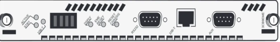
Figure 1 shows the EME front panel.
Figure 1 The EME Front Panel
In the 7-slot chassis, you install the module horizontally as shown in
Figure 1. In the 8-slot chassis and 16-slot chassis, you install the module
vertically, with the LEDs at the top.
The EME module front panel is configured with the following:
■Status LEDs
■
A four-character LED display with a display (DSPLY) button
■One module reset (EME Reset) button
■
One chassis reset (Reset Chassis) button
■
Two RS-232 (serial) port connectors, which are used to connect the
EME to a console terminal or a modem
■
One RJ-45 10BASE-T Ethernet port
ACTIVESTBY 10B-T
DSPL Y
EME RESET RESETCHASSIS
RS232 10B-T AU
X
Status LEDs
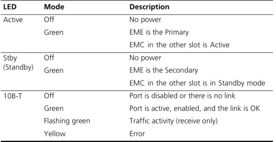
Table 1 lists the status LEDs and explains their modes. If one EME is
installed in the chassis, you can install an EMC in the adjacent slot. If two
EMEs are installed, you cannot install an EMC.
Character Display LEDs
The four-character display LEDs display alphanumeric information about:
■The current operating state of the module.
■
The release number of the EME embedded software.
■
Any environmental fault. For example, when a power supply, fan, or
overheat fault occurs, the fault automatically appears in the character
display.
When you press the DSPLY button, the character display LEDs default to
the module’s operating state.
Table 1
EME Front Panel Status LEDs
LED
Mode
Description
Active
Off
Green
No power
EME is the Primary
EMC in the other slot is Active
Stby
(Standby)
Off
Green
No power
EME is the Secondary
EMC in the other slot is in Standby mode
10B-T
Off
Green
Flashing green
Yellow
Port is disabled or there is no link
Port is active, enabled, and the link is OK
Traffic activity (receive only)
Reset Buttons
The following three reset buttons reside on the front panel of the EME
module. To press any of these buttons, use a pen tip or other nonmetallic
tool.
■
DSPLY button
— Press this button to reset the four-character display
LEDs on the EME front panel to zeroes (0000). The LEDs display
alphanumeric characters that indicate which EME is the primary and
which is the secondary.
■
EME Reset button
— Press this button to reset the EME. Resetting
the EME prevents traffic from reaching the other modules in the
chassis. Press the EME Reset button only if you suspect a problem with
the EME that you cannot fix through management commands.
■Reset Chassis button
— Press this button to reset all the modules
that are installed in the chassis.
CAUTION:
Although resetting the chassis causes a temporary
interruption of the data paths to all of the modules, in some instances
this interruption can become permanent and result in the loss of traffic.
Press the Reset Chassis button only if you suspect a problem with the
chassis that you cannot fix through management commands.
Ports
The following three ports reside on the EME module front panel:
■RS-232 Port
— Shielded male DB9 connector for connecting an
RS-232, two-channel cable for serial communication
■
10B-T Port
— RJ-45 10BASE-T connector for an RJ-45 10BASE-T
Ethernet connection
■
AUX Port
— Shielded male DB9 connector for connecting a second
RS-232, two-channel cable for serial communication
Audience Description
This guide is intended for
trained technical personnel only. Do not
attempt to install, remove, or replace a CoreBuilder 9000 EME if you have
not had the proper training from 3Com. For training information in the
United States and Canada, call 1-800-NET-3COM. For training
information in other countries, visit the 3Com Web site:
http://www.3Com.com/
Safety Precautions
When you install or replace components in a CoreBuilder 9000 system,
be sure that you follow all safety precautions. To avoid electric shocks,
burns, or equipment damage, read and follow these warnings:
WARNING:
Allow only trained service personnel to install, remove, or
replace an EME.
WARNING:
Hazardous energy exists within the system. Use extreme
caution when you install, remove, or replace an EME. When the system is
on:
■
Never insert metal objects such as a screwdriver or a finger with
jewelry into open module slots.
■
Do not touch any connections within the chassis with your hands or
fingers.
ESD Safety Information
Electrostatic discharge (ESD) can damage components of the system.
ESD, which occurs when the EME is improperly handled, can cause
complete or intermittent failures.
CAUTION:
To prevent ESD-related damage:
■
Always wear an ESD wrist strap (not provided) when you handle a
module, ensuring that the strap makes good skin contact and is
properly grounded.
■
Keep the EME in its antistatic bag until you are ready to inspect or
install it.
Handling Precautions
When you handle the EME, follow these precautions:
■Always handle the EME by the front panel only.
■
Do not touch the components, pins, leads, or solder connections.
■When you insert the EME into the module guides, do not twist or
otherwise force the module into the chassis.
■
Before you push the EME module into the chassis, make sure that the
module ejector handles are open.
■
When you slide the EME module into a 7-slot chassis, match the left
and right module guides. When you slide the EME module into the
8-slot chassis and 16-slot chassis, match the upper and lower module
guides.
Unpacking Procedure
Use the following procedure when you unpack the EME module:
1
Verify that the EME is the correct model by matching the 3C number that
is listed on the side of the shipping box to the 3C number that is listed on
your order documentation (3CB9EME).
2
Remove the EME module, in its antistatic bag, from the shipping box.
3
Remove the EME from the antistatic bag and inspect it for damage.
CAUTION:
Handle the module by the front panel only. Do not touch any
components, pins, leads, or solder connections.
If the module appears to be damaged, replace it in the antistatic bag,
place it back in the shipping box, and contact your local supplier.
4
Ensure that the box also contains:
■
CoreBuilder 9000 Release Notes for Management Modules
■Enterprise Management Engine Quick Start Guide for the
CoreBuilder 9000 Enterprise Switch (this guide)
■
CoreBuilder 9000 Enterprise Management Engine Command Quick
Reference booklet
■
One 16-MB DRAM expansion memory card upgrade in its antistatic
bag
All shipping boxes are reusable. After you remove the contents, replace
the packing materials and store the shipping box for future use.
Installation
Prerequisites
Before you install the EME module, comply with the following
prerequisites:
■
Verify that the chassis is properly installed in a rack, on a table, or on a
shelf, according to the instructions in either of these guides:
■
7-Slot Chassis Quick Installation Guide for the CoreBuilder 9000
Enterprise Switch
■
Chassis Quick Installation Guide for the CoreBuilder 9000
Enterprise Switch 8-slot Chassis and 16-slot Chassis
■
Have a flat-blade torque screwdriver available to secure the module to
the chassis after you install it.
■
Read the CoreBuilder 9000 Release Notes for Management Modules
that is included in your module shipping box for important upgrade
procedures for other modules in an existing chassis or in a new
chassis.
CAUTION:
All modules in a CoreBuilder 9000 chassis must operate at
compatible software levels. You must verify the software release on all
new and existing modules in your chassis and upgrade as necessary. See
the CoreBuilder 9000 Release Notes for Management Modules for a
module software compatibility requirements table, mandatory upgrade
procedures, and other important information.
Installing Expansion
Memory
Follow these steps to install the expansion memory card:
1
Locate the expansion memory card slot on the EME module printed
circuit board. See Figure 2.
2
Remove the expansion memory card from its antistatic bag.
CAUTION:
To avoid damage due to static discharge, handle the EME
module by the front panel or edges only.
3
Insert the memory card into the expansion memory card slot on the EME
module. Press the memory card in place so that it is firmly seated.
The memory card is keyed to ensure that you insert it correctly.
Figure 2 The Expansion Memory Card Slot
Expansion memory card slot
EME
front
panel
Installing the EME
Install at least one EME (Model Number 3CB9EME) in each
CoreBuilder 9000 chassis. Each chassis has two slots that are dedicated
for EME installation (slot 8 and slot 9 in the 7-slot chassis, slot 9 and slot
10 in the 8-slot chassis, and slot 17 and slot 18 in the 16-slot chassis).
You can install the first EME in either slot. You can only install one of the
following modules in the second slot:
■
A second EME for standby management support
■An EMC for standby controller support
You do not need to power off the CoreBuilder 9000 chassis to install,
remove, or replace the EME module. You can insert the module while the
chassis is operating. (This is called a hot swap.)
To install an EME module:
1
Before you start the installation process, read “Safety Precautions” and
“Handling Precautions” earlier in this guide.
2
To expose a slot for the module, remove a blank faceplate from slot 8 or
slot 9 in the 7-slot chassis, from slot 9 or slot 10 in the 8-slot chassis, or
from slot 17 or slot 18 in the 16-slot chassis.
WARNING:
Hazardous energy levels exist inside the chassis. Do not place
hands or objects into the chassis or touch any components on an installed
module.
3
Open the module ejector handles (Figure 3).
4
Insert the module into the module guides:
■
For a 7-slot chassis, hold the module horizontally with the LEDs at the
left. The module guides are on the left and right of the slot.
■
For the 8-slot chassis and 16-slot chassis, hold the module vertically
with the LEDs at the top. The module guides are at the top and
bottom of the slot.
CAUTION:
Be careful not to twist or bend the EME module while you
insert it into the chassis.
5
Slide the EME module into the chassis by pressing firmly on the front
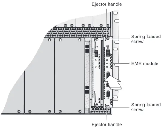
panel. Figure 3 shows how to install the module into a 16-slot chassis.
Figure 3 Installing the EME into the CoreBuilder 9000 16-slot Chassis
6
To engage the EME connectors and backplane connectors, apply pressure
to the module front panel with both hands while you push the ejector
handles inward toward the front panel with your thumbs. You feel a
slight resistance as the connectors engage.
CAUTION:
If the resistance is too great, the EME connectors and
backplane connectors may not be aligned. Forcing the EME inward can
damage the module’s connectors or the backplane connectors. If
necessary, remove and reinsert the EME, ensuring that the connectors are
properly aligned. Do not tighten the spring-loaded screws to seat the
module.
Ensure that the module remains fully seated in the backplane connector
while you close the ejector handles. Push the end of each ejector handle
inward toward the front panel until the ejector handle is parallel with the
front panel.
EME module
Spring-loaded
screw
Spring-loaded
screw
Ejector handle
Ejector handle
7
To secure the module to the chassis, use a flat-blade screwdriver to
tighten the two spring-loaded screws (Figure 3) to Torque Specification 3
to 5 inch-pounds.
To ensure that you tighten screws to Torque Specification, use a torque
screwdriver.
CAUTION:
To ensure adequate cooling airflow, install blank faceplates
over all empty slots.
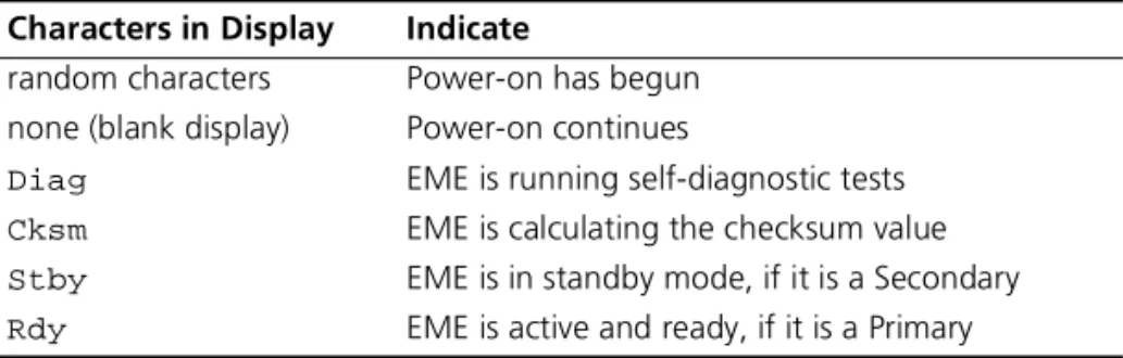
Verifying EME
Operation
To verify that your EME is operating correctly, watch the LED status display
during system power-on. Table 2 shows the sequence of characters that
appears in the LED character display during a successful system
power-on.
Table 2
LED Character Display During Power-on
Characters in Display
Indicate
random characters
Power-on has begun
none (blank display)
Power-on continues
Diag
EME is running self-diagnostic tests
Cksm
EME is calculating the checksum value
Stby
EME is in standby mode, if it is a Secondary
Connecting to a
Terminal or Modem
You need to connect a PC, terminal, or modem to the EME console port
to enter commands to configure and monitor your chassis and EME. You
can manage your system locally through a terminal connection or
remotely using a Telnet or modem connection.
To connect the EME to a terminal or modem, use either the RS-232
Console Port (RS-232) or the RS-232 Auxiliary Port (AUX) connectors that
are located on the EME front panel.
The EME uses male 9-pin connectors. For information about pin
connector assignments and the cable, see Chapter 2 of the
CoreBuilder 9000 Enterprise Management Engine User Guide.
Table 3 describes the access types and what each access type allows you
to do.
Troubleshooting the
EME
If the EME character display shows
CARD
when you power on the EME,
one of these error conditions exists:
■
The expansion card is incorrectly installed.
■The on-board DRAM failed.
If one of these error conditions exists, remove and reinstall the expansion
memory card.
Table 3
Access Types
Access
Type
Allows you to
Using
Terminal
Connect directly to the command interface.
RS-232 serial port
Modem
Access the command interface from remote sites. Auxiliary RS-232
serial port (AUX)
IP
Access the command interface using the
rlogin
or
telnet
commands. Or use an
external SNMP management application to
communicate with the CoreBuilder
®9000 SNMP
agent.
10BASE-T Ethernet
port assigned to an
IP interface
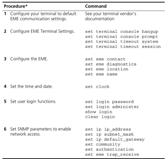
Configuring the EME
Table 4 lists the steps to configure the EME initially.
Configure your terminal to default EME communication settings. See your
terminal vendor’s documentation.
To gain access to the Administration Console of switching modules,
switch fabric modules, and interface modules, use the command:
connect <slot.subslot>
Table 4
EME Configuration Steps
Procedure*
Command
1
Configure your terminal to default
EME communication settings.
See your terminal vendor's
documentation
2
Configure EME Terminal Settings.
set terminal console hangup
set terminal console prompt
set terminal timeout system
set terminal timeout session
3
Configure the EME.
set eme contact
set eme diagnostics
set eme location
set eme name
4
Set the time and date.
set clock
5
Set user login functions.
set login password
set login administer
show login
clear login
6
Set SNMP parameters to enable
network access.
set ip ip_address
set ip subnet_mask
set ip default_gateway
set community
set authentication
set eme trap_receive
* The order of configuration is important in some networks. Read the appropriate sections for more information.
Redundancy
Adding a second EME in slot 9 in the 7-slot chassis, slot 10 in the 8-slot
chassis, and slot 18 in the 16-slot chassis establishes Redundancy.
Redundancy provides standby support in case the first, or primary
, EME
fails for any reason. The standby, or secondary
, EME learns configuration
information from the primary EME and takes over management and
controller responsibility if the primary EME fails.
The
show module all
command lists the status of the management
modules in the chassis (EMEs and EMCs), including which EME is the
primary and which EME is the secondary
.
EME Redundancy
Status
The slot location for each EME determines the redundancy status. If you
install the first EME in slot 8 of the 7-slot chassis, slot 9 of the 8-slot
chassis, or slot 17 of a 16-slot chassis, its status is displayed as
primary
after you enter a
show module all
command. The primary EME has
configuration control, management responsibilities, and fault detection
capabilities for the entire CoreBuilder 9000 Enterprise Switch.
After you install a second EME in the adjacent slot in each chassis, its
status is displayed as
secondary
after you enter a
show module all
command.
3Com recommends that you always install the first EME in the
lower-numbered slot, then install the second EME in the adjacent slot
after the first EME has initialized.
Verifying an Interface
If the interface does not function after a connection is made, view the
status of the interface using the
show interface
command. If the
interface is indicated as down, bring the interface up using the
set
interface index
command.
The
set interface index
command options are:
■Enable
— You can enable the interface.
■Disable
— You can disable the interface.
Examples:
CB9000> show interface
Admin Oper MAC
Idx Network
Type
State State Address
Slot
--- --- --- ---
2 serial_port SLIP
DOWN DOWN N/A
17.02
3 ethernet_portETH
DOWN DOWN
08-00-8f-30-d6-69 17.02
To bring the ETHERNET (ETH) interface up, enter:
CB9000> set interface index enable
Initial Management
Access
Initially, you access the system through the RS-232 serial port connector.
To communicate with the EME serial port after you successfully connect
to the RS-232 connector, configure your PC or terminal to the following
default settings:
■
9600 baud
■8 data bits
■no parity
■1 stop bit
The following message appears on the terminal screen after you properly
connect a terminal to the RS-232 port:
CoreBuilder 9000 Enterprise Management Engine (vX.XX)
Copyright (c) 1999 3Com Corporation.
Login:
You can change the EME terminal settings after you successfully access
the module by entering the
set terminal console
command.
Configuring Network Access to the EME
With network access you can manage the CoreBuilder 9000 chassis from
a remote terminal or SNMP manager. See Chapter 6 in the
CoreBuilder 9000 Enterprise Management Engine User Guide for more
information about using the EME for network access.
To configure the EME for network access:
1
Connect a terminal to the RS-232 serial port.
2
Press Enter to display the
login:
prompt.
3
At the
login:
prompt, enter the default login name:
admin
Use all lowercase. When the system prompts you for a password, press
Enter.
For example:
login: admin
Password: [press Enter]
4
Set the IP address for the EME Ethernet port using the
set ip ip_address <ip address> ethernet_port
command.
For example:
CB9000> set ip ip_address 155.104.10.2 ethernet_port
5
Set the IP subnet mask for the EME Ethernet port using the
set ip subnet_mask <subnet mask> ethernet_port
command.
For example:
CB9000> set ip subnet_mask 255.255.0.0 ethernet_port
6
Set the EME Ethernet port IP default gateway using the
set ip default_gateway <default gateway> ethernet_port
command.
For example:
CB9000> set ip default_gateway 155.104.10.7 ethernet_port
7
To verify the IP address and subnet mask, enter:
show ip
8
If you plan to use an SNMP manager to manage the CoreBuilder 9000
chassis, use the
set community
command to create an entry for the
manager in the EME Community Table.
The following example creates a community named mgt. This community
provides all access privileges for an SNMP manager with the IP address
122.104.10.9:
CB9000> set community mgt 122.104.10.9 all
9
To display the EME in each management slot and to determine which is
the primary or the secondary EME, enter:
show module all
10
To set a login password for access to the EME, enter:
set login password
For example, to set yourself as having normal administrative access to the
EME, enter the following command and respond to the password
prompt:
CB9000> set login password
Enter current password for user admin: [Enter]
New Password: xxxxxx
Admin password changed.
11
If you want to log in to the Administration Console of a switching
module, a switch fabric module, or an interface module, use the
connect
<slot.subslot>
command.
For example:
CB9000> connect 4.1
Menu Options (CoreBuilder
module
- Administer module-level functions
ethernet
- Administer Ethernet ports
bridge
- Administer bridging/VLANs
snmp
- Administer SNMP
disconnect
- Disconnect and return to Management Console
Type ? for help.
Configuring Access to the EME Using the RJ-45 Port
You can manage the chassis from a network management station (NMS)
that is connected to the EME RJ-45 port.
CAUTION:
Do not change the IP address of an EME that is already up
and running from a network connection. Doing so will terminate the
session.
To manage the chassis from the NMS, assign IP connectivity values to the
EME using the commands in the following example:
CB9000> set ip ip_address 141.1102.3.131 ethernet_port
CB9000> set ip subnet_mask 255.255.0.0 ethernet_port
CB9000> set ip default_gateway 141.102.3.2 ethernet_port
You can now access the EME from the NMS. You can also send SNMP and
RMON requests to the EME.
The
set interface
index
command
If the interface does not function after a connection is made, use the
show interface
command to view the status of the interface. If the
interface is indicated as down, use the
set interface index
command
to bring it up.
The
set interface index
command options are:
■Enable
— You can enable the interface.
■Disable
— You can disable the interface.
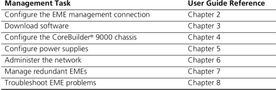
Finding More
Information
For detailed information about using this module, see the
CoreBuilder 9000 Enterprise Management Engine User Guide.
You can view this document online or print it from the
CoreBuilder 9000 Documentation CD-ROM.
Table 5 lists locations of further configuration information in the
CoreBuilder 9000 Enterprise Management Engine User Guide.
Table 5
Tasks in the EME User Guide
Management Task
User Guide Reference
Configure the EME management connection
Chapter 2
Download software
Chapter 3
Configure the CoreBuilder
®9000 chassis
Chapter 4
Configure power supplies
Chapter 5
Administer the network
Chapter 6
Manage redundant EMEs
Chapter 7
CoreBuilder
®9000 Enterprise Management Engine (3CB9EME)
H
ARDWARE 3Com warrants to the end user (“Customer”) that this hardware product will be free from defects in workmanship and materials, under normal use and service, for one (1) year from the date of purchase from 3Com or its authorized reseller.3Com’s sole obligation under this express warranty shall be, at 3Com’s option and expense, to repair the defective product or part, deliver to Customer an equivalent product or part to replace the defective item, or if neither of the two foregoing options is reasonably available, 3Com may, in its sole discretion, refund to Customer the purchase price paid for the defective product. All products that are replaced will become the property of 3Com. Replacement products may be new or reconditioned. 3Com warrants any replaced or repaired product or part for ninety (90) days from shipment, or the remainder of the initial warranty period, whichever is longer.
S
OFTWARE 3Com warrants to Customer that each software program licensed from it will perform in substantial conformance to its program specifications, for a period of ninety (90) days from the date of purchase from 3Com or its authorized reseller. 3Com warrants the media containing software against failure during the warranty period. No updates are provided. 3Com’s sole obligation under this express warranty shall be, at 3Com’s option and expense, to refund the purchase price paid by Customer for any defective software product, or to replace any defective media with software which substantially conforms to applicable 3Com published specifications. Customer assumes responsibility for the selection of the appropriate applications program and associated reference materials. 3Com makes no warranty or representation that its software products will meet Customer’s requirements or work in combination with any hardware or applications software products provided by third parties, that the operation of the software products will be uninterrupted or error free, or that all defects in the software products will be corrected. For any third-party products listed in the 3Com software product documentation or specifications as being compatible, 3Com will make reasonable efforts to provide compatibility, except where the noncompatibility is caused by a “bug” or defect in the third party’s product or from use of the software product not in accordance with 3Com’s published specifications or user manual.THIS 3COM PRODUCT MAY INCLUDE OR BE BUNDLED WITH THIRD-PARTY SOFTWARE, THE USE OF WHICH IS GOVERNED BY A SEPARATE END-USER LICENSE AGREEMENT. THIS 3COM WARRANTY DOES NOT APPLY TO SUCH THIRD-PARTY SOFTWARE. FOR THE APPLICABLE WARRANTY, PLEASE REFER TO THE END-USER LICENSE
AGREEMENT GOVERNING THE USE OF SUCH SOFTWARE.
Y
EAR2000 W
ARRANTY In addition to the Hardware Warranty and Software Warranty stated above, 3Com warrants that each product sold or licensed to Customer on and after January 1, 1998, that is date sensitive will continue performing properly with regard to such date data on and after January 1, 2000, provided that all other products used by Customer in connection or combination with the 3Com product, including hardware, software, and firmware, accurately exchange date data with the 3Com product, with the exception of those products identified at 3Com’s Web site, http://www.3com.com/products/yr2000.html, as not meeting this standard. If it appears that any product that is stated to meet this standard does not perform properly with regard to such date data on and after January 1, 2000, and Customer notifies 3Com before the later of April 1, 2000, or ninety (90) days after purchase of the product from 3Com or its authorized reseller, 3Com shall, at its option and expense, provide a software update which would effect the proper performance of such product, repair such product, deliver to Customer an equivalent product to replace such product, or, if none of the foregoing is feasible, refund to Customer the purchase price paid for such product. Any software update or replaced or repaired product will carry a Year 2000 Warranty for ninety (90) days after purchase or until April 1, 2000, whichever is later.O
BTAININGW
ARRANTYS
ERVICECustomer must contact a 3Com Corporate Service Center or an Authorized 3Com Service Center within the applicable warranty period to obtain warranty service authorization. Dated proof of purchase from 3Com or its authorized reseller may be required. Products returned to 3Com’s Corporate Service Center must be preauthorized by 3Com with a Return Material Authorization (RMA) number or User Service Order (USO) number marked on the outside of the package, and sent prepaid and packaged appropriately for safe shipment, and it is recommended that they be insured or sent by a method that provides for tracking of the package. Responsibility for loss or damage does not transfer to 3Com until the returned item is received by 3Com. The repaired or replaced item will be shipped to Customer, at 3Com’s expense, not later than thirty (30) days after 3Com receives the defective product.
3Com shall not be responsible for any software, firmware, information, or memory data of Customer contained in, stored on, or integrated with any products returned to 3Com for repair, whether under warranty or not.
Dead- or Defective-on-Arrival. In the event a product completely fails to function or exhibits a defect in materials or workmanship within the first forty-eight (48) hours of installation but no later than thirty (30) days after the date of purchase, and this is verified by 3Com, it will be considered dead- or defective-on-arrival (DOA) and a replacement shall be provided by advance replacement. The replacement product will normally be shipped not later than three (3) business days after 3Com’s verification of the DOA product, but may be delayed due to export or import procedures. The shipment of advance replacement products is subject to local legal requirements and may not be available in all locations. When an advance replacement is provided and Customer fails to return the original product to 3Com within fifteen (15) days after shipment of the replacement, 3Com will charge Customer for the replacement product, at list price.
procedures. The shipment of advance replacement products is subject to local legal requirements and may not be available in all locations. When an advance replacement is provided and Customer fails to return the original product to 3Com within fifteen (15) days after shipment of the replacement, 3Com will charge Customer for the
replacement, at list price. This advance replacement is different from the fee-based Advance Hardware Replacement Service, which is available as a contracted service offering.
INCLUDED SERVICES:
Telephone Support, with coverage for basic troubleshooting only, will be provided for ninety (90) days from the date of purchase, on a commercially reasonable efforts basis. Please refer to the Technical Support appendix in the Getting Started Guide for telephone numbers.
3Com’s Web and Bulletin Board Servicesprovide 3Knowledgebase, bug tracking, documentation, release notes, and some software maintenance releases at no charge.
W
ARRANTIESE
XCLUSIVE IF A 3COM PRODUCT DOES NOT OPERATE AS WARRANTED ABOVE, CUSTOMER’S SOLE REMEDY FOR BREACH OF THAT WARRANTY SHALL BE REPAIR, REPLACEMENT, OR REFUND OF THE PURCHASE PRICE PAID, AT 3COM’S OPTION. TO THE FULL EXTENT ALLOWED BY LAW, THE FOREGOING WARRANTIES AND REMEDIES ARE EXCLUSIVE AND ARE IN LIEU OF ALL OTHER WARRANTIES, TERMS, OR CONDITIONS, EXPRESS OR IMPLIED, EITHER IN FACT OR BY OPERATION OF LAW, STATUTORY OR OTHERWISE, INCLUDING WARRANTIES, TERMS, OR CONDITIONS OF MERCHANTABILITY, FITNESS FOR A PARTICULAR PURPOSE, SATISFACTORY QUALITY, CORRESPONDENCE WITH DESCRIPTION, AND NONINFRINGEMENT, ALL OF WHICH ARE EXPRESSLY DISCLAIMED. 3COM NEITHER ASSUMES NOR AUTHORIZES ANY OTHER PERSON TO ASSUME FOR IT ANY OTHER LIABILITY IN CONNECTION WITH THE SALE, INSTALLATION, MAINTENANCE, OR USE OF ITS PRODUCTS.3COM SHALL NOT BE LIABLE UNDER THIS WARRANTY IF ITS TESTING AND EXAMINATION DISCLOSE THAT THE ALLEGED DEFECT OR MALFUNCTION IN THE PRODUCT DOES NOT EXIST OR WAS CAUSED BY CUSTOMER’S OR ANY THIRD PERSON’S MISUSE, NEGLECT, IMPROPER INSTALLATION OR TESTING, UNAUTHORIZED ATTEMPTS TO OPEN, REPAIR, OR MODIFY THE PRODUCT, OR ANY OTHER CAUSE BEYOND THE RANGE OF THE INTENDED USE, OR BY ACCIDENT, FIRE, LIGHTNING, POWER CUTS OR OUTAGES, OTHER HAZARDS, OR ACTS OF GOD.
L
IMITATIONOFL
IABILITY TO THE FULL EXTENT ALLOWED BY LAW, 3COM ALSO EXCLUDES FOR ITSELF AND ITS SUPPLIERS ANY LIABILITY, WHETHER BASED IN CONTRACT OR TORT (INCLUDING NEGLIGENCE), FOR INCIDENTAL, CONSEQUENTIAL, INDIRECT, SPECIAL, OR PUNITIVE DAMAGES OF ANY KIND, OR FOR LOSS OF REVENUE OR PROFITS, LOSS OF BUSINESS, LOSS OF INFORMATION OR DATA, OR OTHER FINANCIAL LOSS ARISING OUT OF OR IN CONNECTION WITH THE SALE, INSTALLATION, MAINTENANCE, USE, PERFORMANCE, FAILURE, OR INTERRUPTION OF ITS PRODUCTS, EVEN IF 3COM OR ITS AUTHORIZED RESELLER HAS BEEN ADVISED OF THE POSSIBILITY OF SUCH DAMAGES, AND LIMITS ITS LIABILITY TO REPAIR, REPLACEMENT, OR REFUND OF THE PURCHASE PRICE PAID, AT 3COM’S OPTION. THIS DISCLAIMER OF LIABILITY FOR DAMAGES WILL NOT BE AFFECTED IF ANY REMEDY PROVIDED HEREIN SHALL FAIL OF ITS ESSENTIAL PURPOSE.D
ISCLAIMER Some countries, states, or provinces do not allow the exclusion or limitation of implied warranties or the limitation of incidental or consequential damages for certain products supplied to consumers, or the limitation of liability for personal injury, so the above limitations and exclusions may be limited in their application to you. When the implied warranties are not allowed to be excluded in their entirety, they will be limited to the duration of the applicable written warranty. This warranty gives you specific legal rights which may vary depending on local law.G
OVERNINGL
AW This Limited Warranty shall be governed by the laws of the State of California, U.S.A., excluding its conflicts of laws principles and excluding the United Nations Convention on Contracts for the International Sale of Goods.P
RODUCTSFederal Communications Commission Notice
This equipment has been tested and found to comply with the limits for a Class A digital device, pursuant to part 15 of the FCC rules. These limits are designed to provide reasonable protection against harmful interference when the equipment is operated in a commercial environment. This equipment generates, uses, and can radiate radio frequency energy and, if not installed and used in accordance with the instruction manual, may cause harmful interference to radio communications. Operation of this equipment in a residential area is likely to cause harmful interference, in which case the user will be required to correct the interference at his or her own expense. Canadian Emissions
Requirements
This Class A digital apparatus meets all requirements of the Canadian Interference-Causing Equipment Regulations. Cet appareil numérique de la classe A respecte toutes les exigences du Règlement sur le matériel brouilleur du Canada.
VCCI Class A Compliance
This is a Class A product based on the standard of the Voluntary Control Council for Interference by Information Technology Equipment (VCCI). If this equipment is used in a domestic environment, radio disturbance may arise. When such trouble occurs, the user may be required to take corrective actions.
EMC D
IRECTIVES
TATEMENTEMC Directive Compliance This equipment was tested and found to conform to the Council Directive 89/336/EEC for electromagnetic compatibility. Conformity with this Directive is based upon compliance with the following harmonized standards:
Warning: This is a Class A product. In a domestic environment, this product may cause radio interference, in which case you may be required to take adequate measures.
L
OWV
OLTAGED
IRECTIVES
TATEMENTLow Voltage Directive Compliance
This equipment was tested and found to conform to the Council Directive 72/23/EEC for safety of electrical equipment. Conformity with this Directive is based upon compliance with the following harmonized standard:
G
ENERALA
PPROVALS
TATEMENTFORUK
UK General Approval Statement This equipment is manufactured to the international Safety Standard EN60950 and is approved in the UK under the General Approval Number NS/G/12345/J/100003 for indirect connection to the public telecommunication network.
A
USTRALIANEMC
F
RAMEWORKSS
TATEMENTAustralian EMC Frameworks Compliance
This product conforms to the EMC Frameworks and meets the Class A limits of AS3548. EN 55022 Limits and Methods of Measurement of Radio Interference EN 50082-1 Electromagnetic Compatibility Generic Immunity Standard:
Residential, Commercial, and Light Industry
Santa Clara, California
95052-8145
this documentation and to make changes in content from time to time without obligation on the part of 3Com Corporation to provide notification of such revision or change. 3Com Corporation provides this documentation without warranty, term, or condition of any kind, either implied or expressed, including, but not limited to, the implied warranties, terms, or conditions of merchantability, satisfactory quality, and fitness for a particular purpose. 3Com may make improvements or changes in the product(s) and/or the program(s) described in this documentation at any time.3Com registered trademarks are registered in the United States and may or may not be registered in other countries. 3Com, the 3Com logo, and CoreBuilder are registered trademarks of 3Com Corporation. All other company and product names may be trademarks of the respective companies with which they are associated.
Part No. 10012725 Published August 1999