The Development of a Site Plan and Flatwork Design
for Good Rest Orphanage
Philip Wolf
California Polytechnic State University San Luis Obispo, California
Good Rest Orphanage, located in Croix Des Bouquets, Haiti, has been supported by Children’s Heritage Foundation (CHF) for over 15 years and was in need of basic site plans and a flatwork design. Proper in field data was collected on a trip to Haiti during the summer of 2019. This material was then assembled in AutoCAD to create six pages of detailed drawings. A flatwork, or sidewalk system was then designed in AutoCAD based off the assembled model. Next an estimate for the cost to construct the sidewalks was developed and refined in excel. Various obstacles were overcome in the process of developing these drawings and estimate from a lack of proper surveying equipment to missing in-field information. The estimate will provide CHF with the necessary information to bid and install a proper flatwork system at Good Rest Orphanage which will increase its resident’s quality of life. These drawings will now be used in all reconstruction and new construction efforts for the future of Good Rest Orphanage.
Key Words: Site Plans, AutoCAD, Flatwork, Haiti, Good Rest Orphanage
Introduction
Good Rest Orphanage is located in a rural city called Croix Des Bouquets, just miles from the main capital of Haiti, Port Au Prince. The land that the orphanage rests on today was purchased sometime back in the 1970’s and Good Rest Orphanage was created. With high poverty rates and lack of jobs many children are abandoned or sent away to places like Good Rest to be taken care of and educated. Good Rest has faced many obstacles over its lifetime with food shortages, lack of funding, minimal leadership, and lack of proper utilities or buildings. CHF began partnering with Good Rest back in the early 2000’s. CHF provides 100% of the funding that Good Rest receives for food, water, electricity, teachers, construction projects, etc.
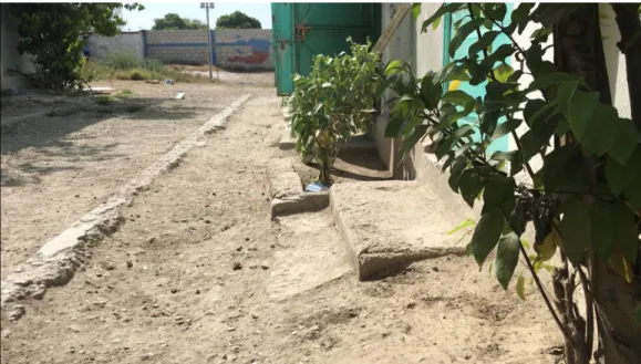
Figure 1. The existing site conditions at Good Rest
In order to do this a proper sidewalk system needs to be designed and estimated, but before that can be accomplished a proper site plan needs to be established. Currently there are no plans or drawings of Good Rest which makes any kind of construction work extremely challenging to plan out. Given that CHF is a nonprofit organization and that all their capital is through fundraising, having proper estimates is important not to waste the generous money or resources that they receive. The
introduction of site plans will give the organization and the orphanage a better ability to plan out and properly estimate new construction or renovations to the property.
Deliverables
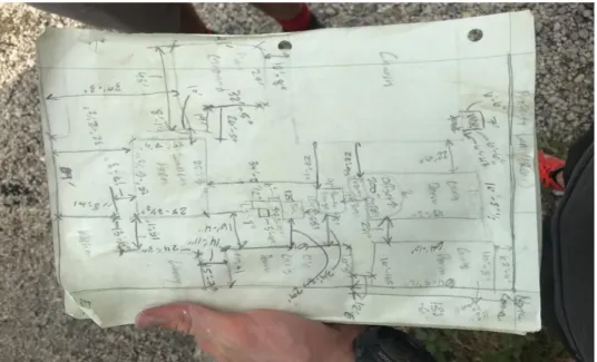
Figure 2. Initial in field drawing with notes.
These measurements were then taken back to the United States and had to be consolidated to give a more organized picture of what the site looked like. This was done by using a piece of 19”x25” paper and using the field notes, initial field drawings, videos, and pictures to assemble a not to scale draft of the site drawing (See Figure 3 Below). This advanced draft was then used as the key source of information and drawing details for the AutoCAD drawing. The estimate could then be completed once the AutoCAD drawing was finished.
Site Plan
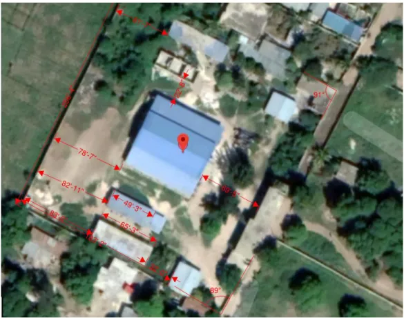
AutoCAD, a computer design software, is where the drawings were compiled. The initial transfer process from paper to AutoCAD faced many obstacles. The drawings and details collected at Good Rest were sufficient for a basic hand drafted drawing of the site, but in a computer program with high precision, the plans did not come together as neatly as would have been hoped. The lack of angles and elevations became clear in the AutoCAD drawing resulting in improper measurements and spacing issues. The plans no longer reflected in field notes or measurements. A trouble shooting process then had to be entered to find what specifically in the drawings was causing the majority of the problems. After meeting with Cal Poly Construction Management faculty members, it was determined that the perimeter walls of the orphanage were the source. The initial AutoCAD drawing had snapped the perimeter walls at perfect 90-degree angles, but this was not what was present in field. Further investigation through the use of calculations from the measurements taken in field determined that angles of greater than or less than 90 existed in all four corners of the property. Google map images from satellites of the site were taken and then put in the PDF editor program, BlueBeam. After scaling the images in BlueBeam rough angle measurements were taken of the four corners of the site, as can be seen in Figure 4. These angle measurements were not exact due to the plant growth that was present in the corners of the site but gave an idea of what the angles were.
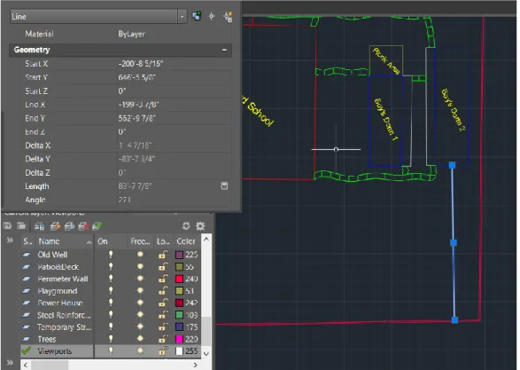
These angles were then applied to the AutoCAD drawing and perimeter walls were adjusted, as necessary. Some of the perimeter walls in-field recorded lengths were not exact once angles were applied, however, due to how these measurements were collected error was present in the recorded lengths which was also confirmed by the google maps images. Once the perimeter walls were set the buildings that were present on the site could be assembled in the model. These buildings were not measured in field as perfectly square, so again necessary adjustments had to be made in the AutoCAD program such as restricting the use of 90-degree angles. Once all buildings had been assembled in the model and matched the in-field specifications they needed to be combined into singular objects using the join command in AutoCAD. These buildings were then moved around the inside of the property until the measurements between each other and the perimeter walls were within one foot of the recorded distances (See Figure 5 Below).
Figure 5. Verifying model dimensions and building placement.
Figure 6. Completed model.
Flatwork Design
The flatwork system that will be installed at Good Rest Orphanage will be a basic design. It will have minimal curves and lack of luxury features that one might find in a sidewalk system in the United States. The flatwork system establishes routes out from all buildings to the school, church, eating area and kitchen, and administration buildings. The design would also need to not cross the areas that are present near the front of the property, as these are used for vehicle traffic and if sidewalks were present in these pathways, they could become damaged and deteriorate. The initial design process for the flatwork required some trial and error. Attempting to find proper routes that would not interrupt vehicle traffic proved to be difficult. After a few design attempts a series of routes were generally established. The drawing of these routes originally was completed using the line command and arc command to give curvature to the design. After completing this design, a fill pattern was attempted to be installed. In AutoCAD a hatch or fill command cannot be completed if a boundary is incomplete (i.e. if a square does not connect at four corners or a series of lines have gaps between them). After the hatch command failed to find a completed area it was determined that gaps existed in the drawing. Using the Pedit command gaps within a series of lines can be filled and the line will be completed and converted into spline (a continuous arching line). However, once the flatwork model was converted to a set of splines the conversion process increased the detail and precision of the flatwork which proved to be too much for the computer to process. AutoCAD began to crash anytime any edits were
Figure 7. Successful flatwork design.
Figure 8. Section cut detail of sidewalk.
Formatting and Publishing
A template for the model would need to be constructed to give details about the drawings as well as allow one to view different parts of the property in greater details. The model would be split up into seven pages of drawings. One page would display the entire site without the flatwork design, four pages would display the site broken down by quadrants to show more detail of the buildings and their dimensions, another page would display the entire site with the proposed flatwork design, and a final page would display the detail drawings of the sidewalks. These pages were formatted on a 24”x32” layout. After studying site plan layouts from other construction projects, a margin was designed that holds the necessary information of the plans. This information includes general site notes, a site pattern key to distinguish what certain areas in the drawing are marked as, the page contents, the author, the date, revision number etc. (See Figure 9 Below).
The process of formatting this template for the seven pages of drawings took time and multiple reviews before the drawings could be finalized and printed to PDF’s. Theses individual PDF’s were then combined into one file using BlueBeam. These files can now be emailed to the director of CHF and printed for in field use.
Estimate
The estimate for the cost of building the sidewalks was completed next. The area tool was used in AutoCAD to take area estimates of the sidewalks. This data was then used to calculate the total cubic feet and cubic yards of concrete that would be needed to complete the project. Linear foot
measurements were also taken in AutoCAD to calculate the amount of formwork that would be required. The total cubic yardage required for this project was 37.85. After these calculations were recorded further consultation was needed by the director of CHF. The director of CHF was able to answers various questions about the concrete pouring process in Haiti, how much labor typically costs, what kind of equipment will need to be rented and how much it costs, as well as price points for various items. Haiti prices for construction materials are relatively the same as those in the United States. With this information in mind the estimate could be assembled using U.S. prices from construction supply stores in the U.S. like the Home Depot, Lowes, and aggregate supply stores. A basic mix design of one part Portland cement, two parts sand or fine aggregate, and three parts gravel or coarse aggregate was used for the concrete portion of the materials estimate. The main challenge was trying to price the fine and coarse aggregate for the project. The director of CHF did not have readily available information on how much the cost of these were by cubic yard or weight in Haiti. The original estimate was assembled without proper calculations in the amount of coarse and fine aggregate needed and with only a price point for buying fine and coarse aggregate by the pound from Quickrete, as opposed to by the cubic yard from an aggregate supplier. Next consultation from industry peers was sought as well as referencing basic RS means data. It was determined that the amount of money required for just concrete materials was too high. After re-examining calculations and using a price point of fine and coarse aggregate by the cubic yard rather than by the pound, the total cost of construction and cost of concrete materials was accurate to the number of cubic yards needed (See Figure 10 Below). The formwork will be 2x6, 16-foot studs. Using the linear foot measurements, the number of studs could be calculated as well as the number of nails, stakes, and steel wire for reinforcement.
Though no schedule was completed for this project, it is estimated that the project will take
somewhere between 8-10 days with a full crew of nine men. This is accounting for the excavation of four inches that will need to be completed before pouring, the laying of decomposed granite, the setting of forms and reinforcement, as well as the actual pour. This information was used to help calculate the price of labor. The estimate also accounted for deliveries, the cost of renting equipment, as well as a seven percent contingency. This total is shown below in Figure 11. The estimate was reviewed by the director of CHF and necessary adjustments were made. The estimate was complete with the grand total of the project coming in at just under nine thousand U.S dollars.
Figure 11. Adding labor and contingency to budget.
Conclusion
Figure 12. Finished Site plan with flatwork design PDF.
Lessons Learned
During this project there were a few major takeaways. The first was that the use of professional surveying equipment is invaluable in the process of assembling a site plan. Though this plan is mostly accurate to within one foot there still exists areas that have discrepancies. The use of surveying equipment would have gathered in field measurements more quickly and efficiently. Less time would have to have been spent on working out the bumps in converting data into AutoCAD. The resulting AutoCAD drawing could have been created with much more detail and efficiency. There is also no such thing as too many notes recorded from in field measurements and drawings. Many videos, pictures and notes were taken while in the field it still was lacking information when it came time to put the information into the AutoCAD drawing. If more notes or pictures could have been taken the drawings could hold more detail, and the more detail the more valuable the drawings are to CHF. Another lesson that can be taken from this project is that the use of AutoCAD can provide someone with essential information and show how their property actually looks on paper. Only a basic amount of skill in AutoCAD is required to complete a set of drawings like this. A person who is more knowledgeable will be able to do this with much more ease and efficiency, but it can be done without great skill or knowledge. When estimating a project like this it is helpful to have a better
understanding of all the moving pieces that go into the scope of the project so that no dollar goes unaccounted for. Understanding the price differences between an area like Haiti and the United States must be taken into consideration as well as the availability of certain materials or equipment.