Diversity-Multiplexing Trade-off for Coordinated
Relayed Uplink and Direct Downlink Transmissions
Chan Dai Truyen Thai, Petar Popovski, Fan Sun and Elisabeth de Carvalho
Department of Electronic Systems, Aalborg University
Email:
{
ttc, petarp, fs, [email protected]
}
Abstract—There are two basic principles used in wireless network coding to design throughput-efficient schemes: (1) aggre-gation of communication flows and (2) interference is embraced and subsequently cancelled or mitigated. These principles inspire design of Coordinated Direct/Relay (CDR) schemes, where each basic transmission involves two flows to a direct and a relayed user. Considering a scenario with relayed uplink and direct downlink, we analyze the Diversity-Multiplexing Tradeoff (DMT) calculating either the exact value or both upper/lower bounds. The CDR scheme is shown to have a higher diversity gain than the reference scheme at any multiplexing gain.
I. INTRODUCTION
Two-Way Relay (TWR) Network Coding (NC) has re-cently emerged as one of the key generic techniques that can boost the throughput performance of wireless networks [2]–[4]. There are two basic principles used in designing throughput–efficient schemes with wireless network coding (NC) (1) aggregation of communication flows - NC operates by having the flows sent/processed jointly; (2) intentional cancelable interference: flows are allowed to interfere over the wireless channel, knowing a priori that the interference can be cancelled by the destination.
TWR NC using the principles mentioned above have been extensively discussed, analyzed and evaluated in many differ-ent aspects. The TWR scenario in which two users exchange messages over a relay and for which TWR NC has been proposed is actually only one of many scenarios in which the principles of flow aggregation and a priori informationcan be used. Several schemes are possibly proposed in many different scenarios using the same principles. One of them is a network with a base station (BS), a relay user (RS), a relayed user (U) and a direct user (V). In this scenario, we have considered different traffic sub-scenarios in each of which one user has an uplink or downlink message. In the proposed coordinated direct/relay (CDR) schemes, the transmissions for the relayed user and the direct user can be combined using theprinciples of flow aggregation and a priori infomration.
For example, for the traffic scenario of relayed uplink and direct downlink, in the first step of the proposed scheme of the scenario, termed S, user U transmits an uplink message to RS and BS transmits a downlink message to user V simultaneously. It becomes a Multiple Access Channel (MAC) at each receiver of RS and user V. Moreover, in the second step, RS decodes and relays the uplink message to BS. If user V can decode this message, its contribution in the first received signal can be cancelled. Therefore, the transmitted
rates and durations are selected and optimized according to several conditions in several options. This will benefit the performance. Enabling such simultaneous transmissions improves the spectral efficiency and communication reliability. The proposed schemes for other traffic scenarios are de-scribed in details in [7] (AF) and [8] (DF). The conventional scheme for each traffic scenario are defined as orthogonal transmissions for the two users. Definitely, TWR NC cannot be used here because there is only one message, uplink or donwlink, requested for the relayed user. In the full traffic scenario, each user has both uplink and downlink messages, the state-of-the-art conventional scheme is defined a com-bination of orthogonal transmissions for the two users and TWR NC scheme. In all full and non-full traffic scenarios, we have analyzed and compared the proposed scheme and the conventional scheme. The proposed scheme was shown to be better in terms of sum-rate and rate region.
The schemes therefore have been so far considered through the prism of spectrum efficiency [5]–[8], in this paper, we will show that the schemes also enhance thecommunication reliability by calculating/bounding and analyzing diversity-multiplexing trade-off (DMT) functions for a conventional scheme and the CDR scheme using DF in traffic scenario of relayed uplink and direct downlink. From now on we simple say “the scenario” to refer to this scenario.
Because DF is used, the rate transmitted by the relay is not necessary equal to the rate it receives, the durations of the all hop transmissions are therefore different and subject to optimization of rates and outage probabilities. Enabling such simultaneous transmissions improves the spectral efficiency and communication reliability.
The rest of the paper is organized as follows. Section II presents the system model used. We describe and calculate rates of the reference and CDR schemes in Section III. Section IV calculates or bounds the DMT functions of the schemes. Section V presents and discusses the numerical results and Section VI concludes the paper.
II. SYSTEMMODEL
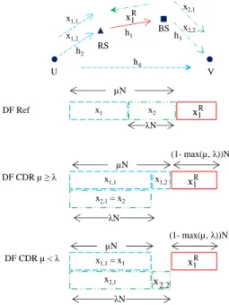
BS RS
x2,2
(1- max(µ, λ))N V U
x1,1
x2,1
R
x1
x1,2 h1 h3
h2
h4
x1 x2 x1R
µN
λN DF Ref
2 , 2 x
(1- max(µ, λ))N µN
DF CDR µ ≥λ x
1,1
x2,1= x2
λN
(1- max(µ, λ))N µN
DF CDR µ < λ x
1,1= x1
x2,1
λN
x1,2 x1R
R
x 1
Fig. 1. Time slots in ReferenceEand CDR SchemeS. In each scheme, the transmissions represented by the rectangles in the same column are conducted simultaneously. The interference is represented by an arrow with thicker head.
The direct channel U–BS is assumed weak and BS gets the information from U only through the decoded/forwarded signal from RS.
BS has to receive messages1from user U via relay RS and send messages2to user V directly. Because we have a relayed uplink and a direct downlink, there are 3 hop transmissions which are U-RS, RS-BS, BS-V hop transmissions through channels h2,h1 andh3. We assume that the transmit powers of the corresponding transmitters in those 3 hop transmissions are PU, PR and PB. The noise at all stations is Additive
White Gaussian Noise (AWGN) with CN(0, σ2), σ2 = 1, distribution.
In the reference scheme denoted asE, all transmissions are orthogonally multiplexed in time. In the CDR scheme denoted asS, transmissions of the two messages are combined in such a way that as much data as possible sent to the desiring stations in the same total time duration. DiU andDiV,i∈ {E, S} are maximal average rates over time for U and V respectively in the whole scheme i. The sum–rate is therefore estimated as Di
S =D i U+D
i V.
Each hop transmission period may consist of one trans-mission or two transtrans-missions with different rates. λ and µ, 0< λ, µ <1, characterize different transmission durations and are defined as follows. In both schemes, there areλNsymbols in the BS-V hop transmission whereN is the total number of symbols in the whole scheme as in Fig. 1. In schemeE, there are totallyµN symbols in U-RS and BS-V hop transmissions; if µ < λ, there is no symbol in U-RS hop transmission and thus no data delivered from user U to BS. This case is therefore not considered. In scheme S, there are µN symbols in U-RS hop transmission. We have different definitions for µ in different schemes as above so that we can easily compare the rates of two schemes as shown later on.RiU[j]andRiV[j]are instantaneous rates in time slotj,j∈ {1,2,3}for user U and
V respectively in schemei,i∈ {E, S}.
We denote C1 = log2(1 + PRγ1), C2 = log2(1 + PUγ2), C3 = log2(1 +PBγ3) and C4 = log2(1 +PUγ4) which are the maximal rates in RS-BS, U-RS, BS-V and U-V hop transmission if there is no interference. Denote C2−1 = log2
1 + PUγ2
PBγ1+1
which is the maximal rate for decoding a desired signal from user U over h2 treating the interference from BS over channel h1 as noise at RS. Similarly, we denote C1−2 = log2
1 + PBγ1
PUγ2+1
, C3−4 =
log2
1 + PBγ3
PUγ4+1
andC4−3= log2
1 + PUγ4
PBγ3+1
. Denote C1,2 = log2(1 +PBγ1+PUγ2) which is the maximal total rate for multiplexing in time between two modes: the first mode decodes the signal from user U treating the signal from BS as noise, cancels its contribution and decode the other signal while the second mode decode in the opposite order because C1,2 = C2,1 = C1−2+C2 = C2−1+C1 [9]. |x| is the number of symbols in symbol streamxandlogmeans base 2 logarithm.
III. SCHEMEDESCRIPTION
In schemeE, the sum–rate will be calculated and optimized based on parameter µ. In scheme S we have two more parameters,RS
U[1]andRSV[1], to optimize.
A. Reference Scheme
First, user U encodess1tox1with rateREU[1]and transmits
it to RS as seen in Fig. 1, RS receivesyR[1] =h2x1+zR[1].
Second, BS encodes s2 to x2 with rate REV[3]and transmits
it to user V, user V receives yV[3] = h3x2+zV[3]. Third,
RS decodes x1 to s1, re-encodes it to xR1 with rate REU[2]
and transmits it to BS, BS receivesyB[2] =h1xR1 +zBU[2].
Sincex1,x2 andxR1 are transmitted with powerPU,PR and
PB, the rates REU[1], R E
V[3] and R E
U[2] are selected as the
maximal rates over the corresponding channels RE
U[1] =C2, RE
V[3] =C3 andREU[2] =C1.
Since all transmissions are performed separately, the du-ration for RS-BS transmission is (1 − µ)N. The U-RS, RS-BS and BS-V transmissions therefore have durations of (µ−λ)N,(1−µ)NandλNsymbols respectively. On the other hand, the corresponding maximal rates are C1, C2 and C3 respectively thus the maximal rate transmitted through them are respectively
DEU
1= (µ−λ)C2, D
E
U2 = (1−µ)C1, D
E
V =λC3. (1) Because the rate transmitted from user U to BS end-to-end is the minimum of the rate transmitted in BS-RS and RS-U transmissions, the sum–rate transmitted for two users is DSE = min DUE
1, D
E U2
+DEV. Because the information of all channels is not available, µ is optimized to have the highest sum–rate based on the distributions of the channels DSoE = maxλ,µD¯ES(λ, µ), where D¯
E
S is the average of D E S
B. CDR Scheme
First, user U transmits x1,1 with rate RU[1]to RS and BS
transmitsx2,1with rateRV[1]inmin(µ, λ)N symbols
simul-taneously. RS and V therefore respectively receive yR[1] =
h2x1,1+h1x2,1+zR[1], yV[1] =h4x1,1+h3x2,1+zV[1].
Second, in |µ − λ|N symbols, U transmits x1,2 to RS yR[2] = h2x1,2+zR[2] if µ ≥ λ or BS transmits x2,2 to VyV[2] =h3x2,2+zV[2]µ λinterference-free with maximal
rates of the corresponding channels C2 and C3 respectively (see Fig. 1). Third, RS decodes x1,1andx1,2, re-encodes and forwards them to BS yB[3] = h1xR3 +zB[3]. Since BS and
RS cannot transmit and receive at the same time, the RS-BS transmission cannot be performed simultaneously with any other transmission, it starts only after both U-RS and BS-V transmissions are finished (the first max(µ, λ)N symbols). Thus|xR
1|=|xR1,1|+|xR1,2|= (1−max(µ, λ))N. We consider two cases as follows.
If C1 > C5, RS can decode x1 when one of the two conditions follows occurs:
• RS decodesx1 treatingx2 as noise: RU[1]≤C2−1. • RS decodes both x1 and x2 according to MAC [9]:
RU[1]≤C2,RV[1]≤C1,RU[1] +RV[1]≤C1,2.
Similarly, user V can decodex2 when one of the two condi-tions follows occurs:
• V decodes x2 treatingx1 as noise:RV[1]≤C3−4. • V decodes both x1 andx2 according to MAC:RU[1]≤
C4,RV[1]≤C3,RU[1] +RV[1]≤C3,4.
IfC1≤C5, because RS transmitxR1 with rateC1, therefore both BS and V can decode xR1. Using the information about s1, the interference in the first slot at V can be completely cancelled thus the condition so that U can decode x2 in the first slot in the case C1> C5 is replaced byRV[1]≤C3.
The rates transmitted in U-RS, RS-BS, BS-V transmissions and the sum-rate transmitted to two users are respectively DSU1 = min(µ, λ)RU[1] + (µ−min(µ, λ))C2, DSU2 = (2− max(µ, λ))C1, DVS = min(µ, λ)RV[1] + (λ−min(µ, λ))C3 withRU[1]andRV[1]satisfying all the conditions mentioned
above. The sum-rate is DSS= min(DUS1, DUS2) +DSV.DSSo= maxλ,µD¯SS(λ, µ), where D¯SS is the average of DSS over all
channel realizations, is the maximum sum-rate.
Above we consider the cases when V has to decode at least s1 or s2 in slots 1 and 2 or in slot 3. The case when V does not need to decode any of them can be achieved by using combining two replicas of the information sent originally by U, each encoded with a different codebook (one used by U and the other by RS). However, such a scheme is outside the scope of this paper.
IV. DIVERSITY-MULTIPLEXINGTRADE-OFFANALYSIS
We first introduce the DMT definition and notations and after that estimate the DMT functions for E andS.
A. DMT Definition and Notations
A scheme is said to achieve spatial multiplexing gainrand diversity gain d if the data rate limρ→∞Rlog(ρρ) = r where ρ
is the corresponding SNR when fading is not considered, and the average outage probability
lim
ρ→∞−
logPe(ρ)
logρ =d. (2)
Throughout the rest of the paper, we use the symbol =. to denote exponential equality, i.e. we write f(ρ) =. ρb to
denote limρ→∞loglogf(ρρ) =b and .
≥, ≤. are similarly defined. Therefore, equation (2) can be written as in [1]
Pe(ρ)
.
=ρ−d. (3)
We also denote(x)+= max(0, x)andlogrefers tolog 2if not stated otherwise. If limρ→∞mn = 1, we write m ∼n when
ρ→ ∞. Becauseρa+ρb∼ρmax(a,b)whenρ→ ∞, we often useρa+ρb=. ρmax(a,b)orρa+1 =ρa+ρ0=. ρmax(a,0)=ρa+
. Moreover,
Pr[γi< x] =
Z x
0
e−tdt= 1−e−x∼x when x→0. (4)
Therefore,
Prγi< ρ−a
.
=ρ−a+ when ρ→ ∞. (5)
We investigate on the outage probability when the system tries to achieve a certain target rate pair (Dt
U, DtV). Here to
consider the diversity-multiplexing trade-off we examine how fast the outage probability decays when the rate increases as a multiple of logρi, where i ∈ {B, R, U}, ρi = σPi2 when stationi transmits with power Pi andσ2= 1is noise power
at a receiver. We assume PB =ρand PR =PU =ρβ as in
[10]. We assume thatβ is always known at all stations. Since the stations have different transmit powers, the target rates have different expressions. We calculate the DMT func-tion for the scheme when the target rate for user i is given byDit=rilogPj whereri is the corresponding multiplexing
gain and Pj is the transmit power of the transmitter i.e. for
direct downlink Pj =PB =ρ and for relayed uplink Pj =
PU =PR=ρβ. The target rate for user U isDtU =rUlogρβ
and the target rate for user V is Dt
V = rV logρ where rU
andrV are multiplexing gains for user U and V respectively.
The scheme is in outage when the maximal achievable rate for user U or user V is smaller than the respective target rate. An outage of a certain pair (λ, µ) is defined as when that pair cannot support a target rate pair (RtU, RtV). Therefore λand µ can be selected such that the average outage probabilities over all channel realizations are the smallest ones(λo, µo) =
minλ,µPr [O]whereOis the event of outage of the scheme.
B. Reference Scheme
As described in section III, the rates for U-RS, BS-V and RS-BS hop transmissions are respectively
DE
U1 = (µ−λ) log(1 +γ2ρ
β)
DE
V =λlog(1 +γ3ρ) DE
U2 = (1−µ) log(1 +γ1ρ
β).
(6)
The delivery of s1 from user U to BS is in outage when one of these two conditions occurs DE
U1 < D
t
Dt
U. We call these two eventsOEU1 andO
E
U2 respectively. The probability of the first event is
Pr
OE U1
= Pr[(1 +γ2ρβ)µ−λ< ρrUβ] .
= Pr[(γ2ρβ)µ−λ< ρrUβ] = Pr[γ2< ρ
rU
µ−λ−1]. (7)
Becauseρ→ ∞, this probability decays only when rU
µ−λ−1<
0. It means that we have a positive diversity gain correspond-ing to this transmission only when1− rU
µ−λ >0. In the other
case, the diversity gain is 0 therefore we can write the diversity
gain as a function of1− rU
µ−λ
+
. On the other hand, because
of (5), we can write Pr
OE U1
.
=ρ−(1−µrU−λ) +
. Similarly, the
probability of the second event isPr
OE U2
.
=ρ−(1−1rU−µ) +
. According to the scheme description, the rate of user V is DEV =λlog(1+ργ3). It is in outage whenDVE< D
t
V. We call
this event OE
V. With some derivations, we have Pr
OE V
.
=
ρ(rVλ −1) +
.
The scheme is in outage when one of the conditions OE U1,
OE U2 andO
E
V occurs i.e. O
E =OE U1 ∪ O
E U2∪ O
E
V. Denoting
d1=β
1− rU
µ−λ
+
,d2= 1−rλV
+
,d3=β
1− rU
1−µ
+ ,
Pr[OE]= Pr[. OE
U1] + Pr[O
E
U2] + Pr[O
E V]
.
=ρ−min{d1,d2,d3} (8) The first equation comes from the fact that the events OE
U1,
OE U2 andO
E
V are independent due to the independence ofγ1, γ2andγ3and that the product of any two or three of the proba-bilitiesPr[OE
U1],Pr[O
E
U2]andPr[O
E
V]decays faster than each
of them. The second equation is due to that the smaller terms are negligible and the probability is determined by the largest term in the sum whenρ→ ∞. According to the definition in (3), the diversity gain is therefore dE = min (d
1, d2, d3). Each element in the min function above is actually the diver-sity gain of each hop transmission (U-RS, BS-V and RS-BS) in the reference scheme. It increases when the corresponding time assigned to it increases (µ−λ,λand1−µ). However, the diversity gain of the scheme is the minimum of them, therefore the time durations assigned to 3 hop transmissions should be balanced such that the minimum diversity gain is maximal. Obviously, the diversity gain can be improved by selecting the right values ofλandµ. This is how we improve the diversity gain when the transmitter and the receiver of a transmission do not know the channels not related to them.dE
o = maxλ,µdE(λ, µ)is the maximum DMT function
scheme E can achieve. It is obvious that dE is maximized when d1=d2=d3 roots of which are optimalµ andλ
C. CDR Scheme
In the first time slot, there are two decoding options at RS: (Option 1) decode x1,1 or x1 treating the interference x2 or x2,1from BS as noise, (Option 2) decode the interference from BS first, cancel its contribution and decode the desired signal. At user V, there are also two similar decoding options: (Option a) decode the signal from user U first and (Option b) decode the signal from BS first. In total, we have four options (1a, 1b, 2a, 2b) however multiplexing of more than one of those options in time with any time ratio also give an achievable rate pair (DS
U, D S V).
On the other hand when ρ→ ∞, C1, C2,C3 andC4 →
∞. If βV < 1, limρ→∞C1−2 = limρ→∞C3−4 = ∞ and limρ→∞C2−1 = limρ→∞C4−3 = 0. Therefore in case of ρ→ ∞ only two decoding options are relevant: 1a (both RS and user V decode the signal from user U first, for larger β) and 2b (both RS and user V decode the signal from BS first, for largerβ). In two cases below (µ≥λandµ < λ), we consider these two options when calculating the DMT function for scheme S. The subscript i/j−k, i, j, k ∈ {B, R, U, V}
means decoding the signal for user j treating the signal for userk as noise at stationiand subscripti/j means similarly but decoding without interference. Similarly to the derivations for Reference Scheme we have the following results.
• µ≥λ
– Option 1a: the rates of three hop transmissions U-RS, BS-V and RS-BS
DS
R/V−U = λlog
1 + γ1ρ
γ2ρβ+1
DUS 1=D
S
R/U = µlog 1 +γ2ρ β
DS
V /V−U = λlog
1 + γ3ρ
γ4ρβ+1
DUS 2=D
S
B/U = (1−µ) log 1 +γ1ρ
β .
(9) There is an outage when one of the following conditions occurs DS
R/V−U < D t V, D
S U1 < D
t U,
DS
V /V−U < D t
V and D S U2 < D
t
U. We have the
DMT function dS > dS−LB−1 = min (d
4, d5, d3) withd4= 1−rλV −β
+
andd5=β
1−rU
µ
+ . – Option 2b: the rates of three hop transmissions
U-RS, BS-V and RS-BS
DSU1 =DSR/U−V = λlog1 + γ2ρβ
γ1ρ+1
+ (µ−λ) log 1 +γ2ρβ
DSV /U−V = λlog1 + γ4ρβ
γ3ρ+1
+ (µ−λ) log 1 +γ4ρβ DS
V =DV /VS = λlog (1 +γ3ρ)
DS U2 =D
S
B/U = (1−µ) log 1 +γ1ρ
β . (10) There is an outage when one of the following con-ditions occurs DSU1 < DUt, DV /US −V < DtU,DSV < DtV, and DSU2 < DUt. We have the DMT function dS > dS−LB−2 = min(max(d1, d6), d2, d3)) with
d6=
β1−rU
µ −λ µ + .
• µ < λ
– Option 1a: the rates of three hop transmissions U-RS, BS-V and RS-BS
DSR/V−U = µlog1 + γ1ρ
γ2ρβ+1
+ (λ−µ) log (1 +γ1ρ) DS
U1 =D
S
R/U = µlog 1 +γ2ρ
β
DSV =DSV /V−U = µlog1 + γ3ρ
γ4ρβ+1
+ (λ−µ) log (1 +γ3ρ) DS
U2 =D
S
B/U = (1−λ) log 1 +γ1ρ
0 0.1 0.2 0.3 0.4 0.5 0
0.1 0.2 0.3 0.4 0.5 0.6 0.7 0.8 0.9 1
r (multiplexing)
d
(
d
iv
e
rs
it
y
)
E2, β = 0.3
SLB2 , β = 0.3
E2, β = 2.5
SLB2 , β = 2.5
Fig. 2. Maximum DMT functiondE
o and lower bound of the maximum
DMT funcitondSo−LBatβ= 0.3andβ= 2.5withrU=rV =r.
dS−LB−3 = min(max(d
7, d8), d5, d9) with d7 = 1−rλV −βµλ
+
, d8 =
1− rV
λ−µ
+
andd9=β
1− rU
1−λ
+ .
– Option 2b: the rates of three hop transmissions U-RS, BS-V and RS-BS
DS U1 =D
S
R/U−V = µlog
1 + γ2ρβ
γ1ρ+1
DS
V /U−V = µlog
1 + γ4ρβ
γ3ρ+1
DS V =D
S
V /V = λlog (1 +γ3ρ)
DS U2 =D
S
B/U = (1−λ) log 1 +γ1ρβ
. (12) Similar to Option 2 in the first case, we have the DMT function dS > dS−LB−4= min(d
2, d9, d10). In summary, dS−LB=
max dS−LB−1, dS−LB−2, dS−LB−3, dS−LB−4
. (13)
dSo−LB = maxλ,µdS−LB(λ, µ) is the lower bound of the
maximum DMT function that schemeScan achieve. Similarly to scheme E, optimal µ and λ can also be written in close forms however not presented here due to its cumbersomeness.
V. NUMERICALRESULTS
We search dE
o and dSo−LB with µ and λ getting values
from 0 to 1 with resolution δµ = δλ = 0.001. As shown in Fig. 2, although having the same maximum diversity gain of 1 (β = 2.5) and of 0.3 (β = 0.3), scheme S has a higher diversity gain at any multiplexing gain and also the higher maximum multiplexing gain than scheme E. In schemeE, because the three hop transmissions are conducted orthogonally in time and rU = rV, the maximum DMT
function or the minimum outage probability is achieved when the durations of the three transmissions are equally balanced. The maximum multiplexing gain is thus 13.
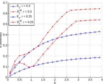
Fig. 3 shows the DMT functions versusβ, whenβis near 1, the signal from user U and the signal from BS equally strong
0 0.5 1 1.5 2 2.5 3 3.5 4
0 0.1 0.2 0.3 0.4 0.5 0.6 0.7
β
d
(
d
iv
e
rs
it
y
)
E2, r = 0.3
SLB
2, r = 0.3
E2, r = 0.25
SLB2, r = 0.25
Fig. 3. dE o anddS
−LB
o r= 0.3andr= 0.25.
when ρ → ∞, the successive interference cancellation does not help therefore schemeS has the same DMT function with schemeE at these values.
VI. CONCLUSION
We describe and calculate the user rates and sum-rate of the reference and CDR schemes for relayed uplink and direct downlink transmission. We calculate the Diversity-Multiplexing Trade-off functions either the exact value or both upper/lower bounds of the schemes. The CDR scheme is shown to have a higher DMT function at any multiplexing gain as well as the higher maximum multiplexing gain than the reference scheme.
ACKNOWLEDGMENT
This work is supported by the Danish Research Council for Technology and Production, grant nr.09−065035.
REFERENCES
[1] L. Zheng and D. N. C. Tse, “Diversity and multiplexing: A fundamental tradeoff in multiple antenna channels,” IEEE Trans. Inform. Theory, vol. 49, pp. 1073-1096, May 2003.
[2] P. Popovski and H. Yomo, “Bi-directional Amplification of Throughput in a Wireless Multi–Hop Network,” IEEE VTC, Spring 2006.
[3] S. Katti, S. Gollakota, and D. Katabi “Embracing Wireless Interference: Analog Network Coding,” ACM SIGCOMM, 2007.
[4] H. Ning, C. Ling, and K. K. Leung, “Wireless Network Coding with Imperfect Overhearing,” arXiv:1003.4270v1 [cs.IT] 22 Mar 2010. [5] C. Thai and P. Popovski, “Coordinated Direct and Relay Transmission
with Interference Cancelation in Wireless Systems,” IEEE Comm. Letters, vol. 15, no. 4, April 2011, pp. 416-418
[6] C. Thai, P. Popovski, M. Kaneko and E. Carvalho, “Coordinated Trans-missions to Direct and Relayed Users in Wireless Cellular Systems,” in Proc. IEEE ICC, Kyoto, Japan, Jun 2011.
[7] C. Thai, P. Popovski, E. Carvalho and M. Kaneko, “Wireless cellular sys-tems with Coordinated direct/relayed users and twoway traffic,” ABCD. [8] C. Thai and P. Popovski, “Coordination of Regenerative Relays and Direct Users in Wireless Cellular Networks,” in Proc. IEEE ISWCS’11, Aachen, Germany, Nov 2011.
[9] D. Tse and R. Viswanath, “Fundamentals of Wireless Communications,” Chap. 8, Cambridge Press, 2005.