Heavenly Bodies RSVP
Final Design Review
June 5, 2020
Team:
Project Members: Jack Boulware Braden Lockwood
Justin Spitzer Allison Turnbaugh
rsvpheavenlyengineers@gmail.com
Sponsor: Dr. Antonio Barata
Music Department
Statement of Disclaimer
Executive Summary
The purpose of the Heavenly Bodies RSVP project was to design and fabricate planet props, as well as a mechanism by which they could be raised and lowered in California Polytechnic State University’s Pavilion theater. The project team was comprised of four fourth year mechanical engineering students: Allison Turnbaugh, Braden Lockwood, Jack Boulware, and Justin Spitzer. We conducted extensive research to determine the ideal solution for the design problem brought to us by our sponsor. In our analysis, we discovered that the most important aspects of our design were the absolute reliability of the system, fire retardant material selection, and the overall aesthetics of the planets. These criteria along with our past product research allowed us to design a product that aligned with the vision of our sponsor. The system of planets was planned for use
by the Music Department for the 25th installment of their annual diverse transmedia series entitled
RSVP XXV: Call and Response. Sponsored by Dr. Antonio Barata, the show’s artistic director
and producer, and professor in Cal Poly’s Music Department, the project featured design
Contents
Executive Summary ... i
List of Figures ... iv
List of Tables ... v
1.0 Introduction ... 1
2.0 Background ... 2
2.1 Information from Sponsor Interviews ... 2
2.2 Product Research ... 3
2.3 Patent Research ... 5
2.4 Safety Obligations ... 6
3.0 Objectives: ... 7
3.1 Problem Statement ... 7
3.2 Customer Wants and Needs ... 7
3.3 Boundary Diagram ... 8
3.4 Quality Function Deployment (QFD) ... 8
3.5 Engineering Specifications ... 8
4.0 Concept Design ... 10
4.1 Concept Development ... 10
4.2 Initial Top Concepts ... 11
4.3 Concept Selection Process ... 14
4.4 Selected Concept ... 15
4.5 Preliminary Analysis ... 16
4.6 Current Design Risks ... 17
5.0 Final Design ... 18
5.1 Wind-Up Rod Assembly ... 18
5.2 Pulley System... 20
5.3 Planet Assembly ... 21
5.4 Safety and Maintenance ... 22
6.5 Testing Status due to COVID-19 ... 29
7.0 New Project Scope & Results ... 31
7.1 Altered Problem Statement & Project Scope ... 31
7.2 Ideation and Analysis for New Scope ... 31
7.3 Instructables for Future Engineers/Theatre Productions ... 31
8.0 Project Management ... 32
8.1 The Design Process ... 32
8.2 Plan up to Critical Design Review ... 32
8.3 Plan Up to Final Design Review ... 33
8.4 Plan Changes due to COVID-19 ... 33
8.5 Remaining Issues ... 34
9.0 Conclusions & Recommendations ... 35
References ... 36
Appendix A: QFD: House of Quality ... A-1
Appendix B: Ideation and Decision Phase ... B-1
Appendix C: Decision Matrices ... C-1
C.1 Pugh Matrices ... C-1
C.2 Weighted Decision Matrix ... C-3
Appendix D: Hand Calculations ... D-1
Appendix E: Design Hazard Checklist ... E-1
Appendix F: Design Failure Mode and Effects Analysis ... F-1
Appendix G: Indented Bill of Materials (iBOM) ... G-1
Appendix H: Design Verification Process ... H-1
Appendix I: Purchased Parts ... I-1
Appendix J: Full Drawing Package ... J-1
Appendix K: Instructables ... K-1
List of Figures
Figure 1. Beach Ball [1] ... 4
Figure 2. Styrofoam Balls [2] ... 4
Figure 3. Strong Wire Rope [3] ... 4
Figure 4. Pulley [4] ... 4
Figure 5. Electric Motor [5] ... 4
Figure 6. Glow in the Dark Paint [6] ... 4
Figure 7. Phantom of the Opera Chandelier [7] ... 4
Figure 8. Wahlberg DMX Winch [8] ... 5
Figure 9. Exercise Ball [9] ... 5
Figure 10. Boundary Diagram... 8
Figure 11. Sketch of Wire Frame Planet ... 11
Figure 12. Sketch of Plastic Shell Planet ... 11
Figure 13. Sketch of Cross Plate Planet ... 11
Figure 14. Sketch of looped connection ... 12
Figure 15. Sketch of adhesive connection ... 12
Figure 16. Sketch of bolted connection ... 12
Figure 17. Sketch of the wind-up rod ... 12
Figure 18. Sketch of the levers ... 12
Figure 19. Sketch of the pulleys ... 12
Figure 20. Sketch of the motor that will attach to our shaft ... 13
Figure 21. Sketch of manually operating the mechanism ... 13
Figure 22. Sketch of a gear train that will control our shaft ... 13
Figure 23. System 1 Components and Connections ... 13
Figure 24. System 2 Components and Connections ... 13
Figure 25. System 3 Components and Connections ... 14
Figure 26. System 4 Components and Connections ... 14
Figure 27. System 5 Components and Connections ... 14
Figure 28. System 6 Components and Connections ... 14
Figure 29. Model of Chosen Concept ... 15
Figure 30. Model of Rotating Shaft for Chosen Design ... 16
Figure 31. Concept Prototype ... 16
Figure 32. Exploded View of Wind-Up Rod Assembly ... 18
Figure 33. Base Structure ... 19
Figure 34. Shaft System with Differing Diameters ... 19
Figure 35. Isometric view of Wind-Up Rod Assembly ... 19
Figure 36. Top View and Front View of Grid Layout ... 20
Figure 37. Floor Plans with Lighting ... 21
Figure 46. Deflated Beachball with Fiberglass Tape ... 30
Figure 47. Pugh matrix determining the connection between the spheres and system ... 1
Figure 48. Pugh matrix used to determine planet material. ... 1
Figure 49. Pugh matrix used to determine the mechanism for raising and lowering the spheres. ... 2
Figure 50. Pugh matrix used to determine methods of propulsion for the planets. ... 2
List of Tables
Table 1. Relevant Products and their Characteristics ... 4Table 2. List of Relevant Patents and their Characteristics ... 6
Table 3. Customer Wants and Needs ... 7
Table 4. Engineering Specifications ... 9
Table 5. Morph Matrix Options ... 10
Table 6. Planet Design Ideas ... 11
Table 7. Attachment Ideas ... 12
Table 8. Vertical Movement Ideas ... 12
Table 9. Propulsion Ideas ... 13
Table 10. Intended Design Deliverables and Due Dates ... 32
Table 11. Ideas for moving the planets ... 1
Table 12. Ideas for controlling planetary movement... 2
1.0 Introduction
2.0 Background
After accepting the project, the team completed introductory work in clarifying the problem, researching possible solutions, and establishing communication with critical staff and faculty members, who were instrumental in discovering solutions to the presented problem. Through more communication with the theatre technicians, we have included more information regarding safety standards and a relevant product: a DMX winch. During our design process we tested possible methods of creating the planet models and determined the most reliable solution would be to utilize large exercise balls and create a suspension system for the balls which will not puncture them.
2.1 Information from Sponsor Interviews
In the earliest stage of the project, our team met with Dr. Barata to clarify the nature of the project itself. In the first weeks, the primary focus was gaining a better understanding of what Dr. Barata desired, in addition to learning considerations which were not evident beforehand. During this time, the team walked through the Pavilion black box theatre to gain first-hand experience of the space and its limitations. The Pavilion is a 72 ft by 42 ft theatre space on the far right of the main entrance to Harold Miossi Hall in Cal Poly’s Performing Arts Center (PAC). Within the Pavilion, there is a structure that spans the width and length of the ceiling referred to as “the grid,” to which all stage lights and speakers are mounted. The grid would support the planets; ideally planets will span the full length of the grid. Dr. Barata explained that the stage would be set against one wall of the theater; consequently, there may be space for a human to operate the planetary system behind the curtain.
In subsequent meetings with our sponsor, the team connected with Mr. Tim Seawell, Head Carpenter for the PAC, and Mr. Tom McPherron, its Technical Director. Mr. Seawell and Mr. McPherron were valuable resources concerning theater regulations, the Pavilion’s technical
specifics, and the finer points of theater tech. Meeting with Mr. Seawell and Mr. McPherron
clarified several concerns the group had regarding what was possible in the theater space. For example, the team learned that aircraft cable is often used to support weight from the grid, as it is nearly invisible while holding items and has proved effective in the past. We were also made aware that the theatre department uses safety factors of approximately 7-9; this means the system needed to be able to hold 7-9 times the actual load of the planetary bodies. In addition, the maximum
temperature recorded near stage lights attached to the grid is 150°F; our final design had to be able
to withstand this temperature. Mr. Seawell and Mr. McPherron also recommended researching systems called a DMX winches. These are self-contained systems that can clip to the grid, using an internal motor to raise and lower objects individually.
2.2 Product Research
We conducted introductory research into methods by which the planetary bodies could be manufactured, moved, and held. Though our team could not initially find exact matches for the desired system already available on the market, we researched designs which could prove essential to the project going into the ideation phase. After speaking with Mr. Seawell and Mr. McPherron, we researched DMX winches, which could constitute a more direct solution to the proposed problem.
Table 1. Relevant Products and their Characteristics
Related Product Product Description
Figure 1. Beach Ball [1]
Beach balls were researched for their potential use in the construction of large planetary bodies. They are lightweight and spherical, which were two of the most important design specifications for planet designs. It would have been necessary to coat the balls with a hardening agent that ensured the balls would not deform or ‘pop’ while in use.
Figure 2. Styrofoam Balls [2]
Styrofoam balls were also researched for their potential use in the construction of small planetary bodies. Styrofoam is a very light-weight material and holds its shape better than inflatable alternatives. Unfortunately, the largest Styrofoam balls available on the market had a diameter of 1 foot, which is smaller than the group required for most planet props.
Figure 3. Strong Wire Rope [3]
Strong wire rope was also an option for our design. It was important that the material used be strong enough to support the planets and durable enough to withstand wear and tear. However, it was also important for the wire to be as thin as possible, rendering it invisible to the audience.
Figure 4. Pulley [4]
Pulleys were also considered to create our system. The system would require one pulley for every planet as well as extra pulleys to ensure wires can all connect back to a common mechanism (most likely a motor).
Figure 5. Electric Motor [5]
A motor could help retract the wire and run the pulley system. Though Dr. Barata believed this action could be performed by a person, our team believed it will be more consistent and reliable to find a mechanical solution. A motor would have allowed us to lower the planets at a very consistent, steady speed.
Figure 6. Glow in the Dark Paint
[6]
Glow in the dark paint was considered to suit the project’s aesthetic needs. It is important that the planets make a visual impact on the audience and glow in the dark paint would be an effective tool in achieving this. In addition, Dr. Barata has spoken about his desire to have some form of luminescence coming from the planets.
Figure 7. Phantom of the Opera
Chandelier [7]
Table 1. Relevant Products and their Characteristics
Related Product Product Description
Figure 8. Wahlberg DMX Winch
[8]
The Wahlberg DMX Winch is a device designed to lift electrical stage items at loads of up to 22lbs. The winch can be controlled by 16-bit position down to the millimeter. The lowering and raising speed of the system varies from 2-11.8 in/s.
Figure 9. Exercise Ball [9]
Exercise balls could serve as easy planet props, assuming there is no risk related to heat resistance. Because they can be ordered in a variety of sizes, they could be used to simulate many different planets, if a suitable way to hang them from the grid was devised.
2.3 Patent Research
Table 2. List of Relevant Patents and their Characteristics
Patent Name Key Characteristics
Flexible Lightweight Overhead Storage Rack
[10]
• Hanging Storage Device
• Utilizes Pulley Systems
• Holds items in positions high off the ground
Portable Game Hoist [11]
• Can be secured to rafters
• Operates with a pulley and a crank
• Moves objects up and down vertically
Compound winding apparatus and counterbalance system [12]
• Compound counterbalance system
• Holds weight of window up
• Allows for only vertical movement
Cable and pulley linkage for exercise machine [13]
• Multiple pulley system
• Strategic weight distribution based on pulley placement
• System that supports weight moving up and down consistently through multiple cycles
Apparatus for moving scenery [14]
• Operates in a theatrical setting
• Utilizes a pulley system to raise or lower theatre scenery
• Possible to pre-set heights that the scenery is lowered to and the speed that it is lowered at
Suspended theatre rise system [15]
• Operates in the theatrical space
• Uses counterbalance to lower and raise weights
2.4 Safety Obligations
3.0 Objectives:
After gathering all the necessary background information on our project, we moved onto defining our problem and better understanding the specific requirements of the project. We also amended a few of our engineering specifications at the request of our sponsor and based on the limitations of our final design.
3.1 Problem Statement
Cal Poly RSVP needed a way to suspend, store and deploy numerous planetary bodies for a production, directed by Dr. Barata, because there was no system that could raise and lower the bodies to carry out Dr. Barata’s vision. The mechanism designed needed to be safe, quiet, reliable, and complete by the day of load-in during the early weeks of May.
3.2 Customer Wants and Needs
Through discussion with our sponsor and staff working in the Performing Arts Center, we highlighted key considerations which were necessary during the design process. For instance, the method of propulsion needed to move the mass of approximately 20 ‘planets’, the heavenly bodies had to be fire retardant to be allowed within the theater, and a silent mechanism was preferred to maximize the ‘wow factor’ experienced by the audience. While many of the desired qualities of the project, such as size or weight, could be represented empirically, some were more abstract. For instance, though Dr. Barata stressed how important it was to have a “completely reliable” system, it was difficult to quantify that desire. It is easy to understand what was required; there must be complete certainty that the system would work through the end of the production. All the necessary requirements set forth by our customers as well as the extra features desired can be seen in Table 3.
Table 3. Customer Wants and Needs
Wants Needs
Aesthetically pleasing Safe for operators & performers
Hidden from audience Near-silent operation
Variable movements Raise and lower on command
Smooth consistent movements Fire Retardant
No interference with stage lighting Spheres of varying sizes
3.3 Boundary Diagram
To accurately define the scope of our project, we created a boundary diagram. A boundary diagram is used to see what is within our control and what is out of our control regarding the project. Everything within the dotted line of Figure 10 was within our control. The Pavilion grid was not within our control because we could not make alterations to it; however, the dotted line goes through it because we needed to attach our system to the grid. In addition, we included the seating arrangement in the boundary diagram because our design had to consider where the audience was in relation to the planets. For example, any planets hanging over the audience could not move too low, as they would have obstructed their view or collided with the audience.
Figure 10. Boundary Diagram
3.4 Quality Function Deployment (QFD)
With past research completed the next step in our process was to complete a QFD, also known as a House of Quality graph. The purpose of the QFD was to ensure that the design chosen would most effectively fulfil the customer’s desires. To do this, we set out to define who our customers were, their needs and wants, what solutions existed at the time, and how we could specify these quantities. All categories were evaluated with numerical values or symbols and used to determine what specifications were the most important to our design. Our analysis showed that heat resistance, consistent function, and aesthetics proved to be our most important design criteria. To see more, tour complete QFD can be found in Appendix A.
3.5 Engineering Specifications
Table 4. Engineering Specifications
Spec #
Specification Description
Requirement or Target
(units) Tolerance Risk Compliance
1 Production Cost $3000 Max. M A
2 Total System Weight 50 lb Max. L A, I
3 Individual Planet Weight 5 lb Max. L A, T
4 Operating Volume 35 dB 5 dB M T, I
5 Operating Speed 8 ft/sec ft/sec H A, T
6 Heat Resistance 150 F Min. H A, T
The requirements for cost operating volume and weight were established based on previous RSVP senior projects and the requirements for our specific project [19,20]. We concluded to aim for 35 dB operating volume, because 40 dB is comparable to a computer running or a babbling brook and 30 dB is comparable to a whisper; an operating speed within that range would be ideal [21]. However, an operating volume of 30 dB was not considered a minimum, because anything below 30 dB would not distract from the performance and was therefore an acceptable operating condition. Because we would need to fabricate around 20 planets of varying sizes, purchase ropes, pulleys, and potentially a motor, we anticipated cost to be approximately $3,000, including the cost for technicians to install the system. We aimed to minimize the weight of the planets and the overall system, such that it would only require two people to install and to ensure we would not overload the grid. We would test compliance for total system weight by first calculating the anticipated weight, which was compared to the weight of all individual components. We would also confirm that the system works ergonomically by testing if two people could lift the system. The same process was used to test the weight of the individual planets. The operating volume of the system in a quiet room would also be measured. Operating speed would be tested similarly, by measuring the speed of the rising and lowering planets. To test the heat resistance of the planets, we planned to conduct preliminary tests with a theatre light to determine which materials are the least effected by the heat. We anticipated that any feasible material which reaches a temperature
above 150 F would deform such that the overall aesthetic will be compromised.
3.5.1 High Risk Specifications:
4.0 Concept Design
Using the information collected, the team set out to generate concepts that could be developed into a final product. In the following section we will detail the process we went through to obtain our final design as well as preliminary tests and current concerns.
4.1 Concept Development
Initially, we performed Functional Decomposition, which broke down the overall project into subsystems, known as functions, to brainstorm ideas based on these functions. We considered four functions: planet design, method of connection, method for vertical movement, and method of propulsion. By understanding what the system needed to do on a base level, this allowed us to generate ideas to fulfill these functions. With all functions listed out on a white board our team began brainstorming as many ideas as possible that could achieve the specific functions we created. All ideas generated through this brainstorming session are in Appendix B. After brainstorming ideas, our team generated more ideas by brainwriting and brain sketching. In these activities each team member wrote and drew specific ideas for each function in a logbook. In each session, five minutes were allotted to each team member to create ideas for the respective function. At the end of the five minutes, the books were passed to a new team member until all members had generated
ideas for each function. To see all additional ideas generated from these exercises seeAppendix
B.
Once all initial ideas were generated, they were placed into a Pugh Matrix. The Pugh Matrix allowed the team to evaluate the ideas generated for each function against a specific baseline or datum concept. For example, our datum concept for propulsion of the planets is a motor. With reference to our datum, other ideas of propulsion were assessed such as: manual, drill power, counterweights, or gear trains. These ideas were assigned positive, neutral, or negative rankings relative to the datum for various criteria like noise level and cost. For a full listing of all Pugh Matrices see Appendix C.
From the Pugh Matrices the top three ideas for each function were placed in a Morph Matrix, its purpose is to take individual ideas and combine them into a fully functional system. Starting from the left side of Table 5 and moving to the right, lines are drawn to combine the function ideas into a system. Each system created contains one of idea from each of the functions in Table 5.
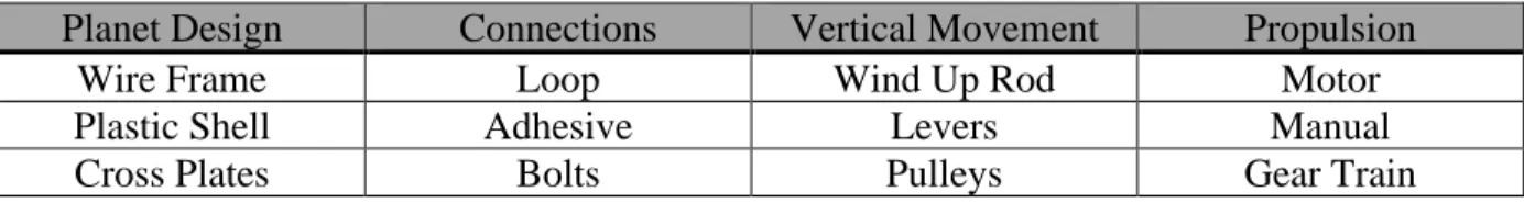
Table 5. Morph Matrix Options
Planet Design Connections Vertical Movement Propulsion
Wire Frame Loop Wind Up Rod Motor
Plastic Shell Adhesive Levers Manual
Cross Plates Bolts Pulleys Gear Train
4.2 Initial Top Concepts
4.2 Initial Top Concepts
After the completion of our Morph Matrix we were left with a total of six plausible systems to continue our design with. Each of the top function ideas listed in Table 5 are further explained in Tables 6-9.
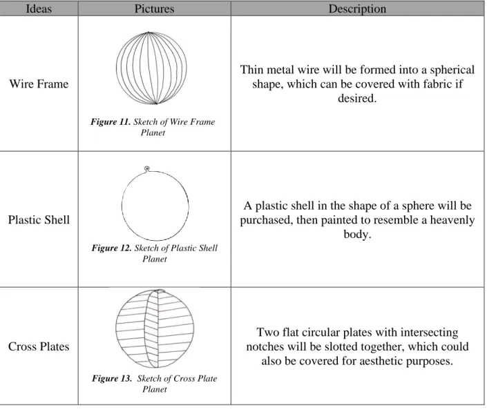
Table 6. Planet Design Ideas
Ideas Pictures Description
Wire Frame
Thin metal wire will be formed into a spherical shape, which can be covered with fabric if
desired.
Plastic Shell
Figure 12. Sketch of Plastic Shell
Planet
A plastic shell in the shape of a sphere will be purchased, then painted to resemble a heavenly
body.
Cross Plates
Figure 13. Sketch of Cross Plate
Planet
Two flat circular plates with intersecting notches will be slotted together, which could
also be covered for aesthetic purposes.
Figure 11. Sketch of Wire Frame
Table 7. Attachment Ideas
Ideas Pictures Description
Loop
Figure 14. Sketch of looped
connection
A loop on the end of our cable will be carabiner clipped onto the planet
Adhesive
Figure 15. Sketch of adhesive
connection
The end of our cable will be attached with a strong epoxy directly to the planet
Bolts
Figure 16. Sketch of bolted
connection
The cable with plate attachment will lower onto our planet and bolt through the plate into the
planet
Table 8. Vertical Movement Ideas
Ideas Pictures Description
Wind Up Rod
Figure 17. Sketch of the wind-up rod
A shaft with various diameter circles welded on will allow cable to loop over diameters and
allow for variable planet lowering speed
Levers
Figure 18. Sketch of the levers
A “teeter-totter” design will have one shaft running along the grid with several supporting
planks from which planets are suspended
Pulleys
Figure 19. Sketch of the pulleys
Table 9. Propulsion Ideas
Ideas Pictures Description
Motor
Figure 20. Sketch of the motor that
will attach to our shaft
A motor purchased online will be used to rotate the shaft and lower the planets
Manual
Figure 21. Sketch of manually
operating the mechanism
A person standing with a rope will pull up and down on a cable to rotate a shaft in order to
raise and lower the planets
Gear Train
Figure 22. Sketch of a gear train that
will control our shaft
A gear train will be used with a motor connected directly to the shaft allowing for
variable control of the shaft
The ideas accumulated in Tables 6-9 were combined in a variety of ways to create fully functioning systems that meet all necessary function requirements. Our various system ideas are represented by the block diagrams of Figure 23- 28 and show the viable combinations that were revealed through ideation. Once all the systems were decided we analyzed the systems against our project criteria to determine which idea was the best.
System 2 allows for easy manufacturing of sphere shell and will allow for strong connection with the bolts. The lever design will allow for planets to rock up and down while having variable control from the gear train attached to the shaft.
Figure 25. System 3 Components and Connections
Like System 2, System 3 gives easy access to planet manufacturing as well as a strong connection clipped on to the cable and a hook attached to the planet. This will all be connected to the multi diameter rod allowing for carriable speed control that will be operate manually which will reduce noise and cost.
Figure 26. System 4 Components and Connections
Differing from the previous two ideas, this system uses lightweight wire frame and adhesive to avoid complications with other attachments. Pulleys are also used as they have proved efficient in prior theater productions as well as a motor to provide consistent power to the system.
Figure 27. System 5 Components and Connections
This system is very similar to the system in Figure 26, the only difference is the planet material choice, this design allows for easier manufacturability.
Figure 28. System 6 Components and Connections
This system is very similar to that of Figure 25, except the planet material has also changed. The benefit of this system is that it will be cheaper to create and be lighter in weight than the previous option.
A seventh fully functional system that already exists called a DMX winch (see Table 1 Figure 8.) was discovered in our design process and added as another possible option. This solution is the most high-tech and requires the least amount of construction materials. The system of powered winches would be able to lock into the grid and operate without any mechanism behind the stage. The winches can be programmed to move however we want them to move making this option very simple.
4.3 Concept Selection Process
results for this test can be found in Appendix C and will be discussed further in section 4.4 Selected Concept.
4.4 Selected Concept
In the end, we decided to select the design featuring a rotating shaft of varying diameter controlled by a motor in conjunction with the planets being made of wire frame or a plastic shell. These planets will be connected to system via the loop method described previously. This concept will also utilize pulley to guide the planets to their predetermined drop location. The different diameters of the shaft will allow the planetary bodies to be lowered at different distances from the ground while still dropping at the same speed. In total, there will be four or five shafts each controlling approximately five planetary bodies. These shafts will be positioned at different locations to ensure that the heavenly bodies can cover the whole stage and part of the audience. Ideally, these shafts will be positioned behind the curtains as to hide the mechanism from the audience and add to the wonder and surprise when the planets eventually descend from the grid.
Figure 29. Model of Chosen Concept
Figure 29 shows the overall concept while not including the wire connecting the shaft to the planetary bodies. The wire was neglected for this 3D model for the sake of visual clarity.
Part of Existing
Pavilion Grid Pulleys
Heavenly Bodies
Figure 30. Model of Rotating Shaft for Chosen Design
Figure 30 shows a 3D model of our proposed rotating shaft. The overall length of the shaft had yet to be determined as was dependent on the space available behind the curtain and where the curtains were to be placed in relation to the stage, which had yet to be decided at that time. In addition, the radial size of the disks was decided based on future calculations of where each planet was to be placed and how far the planet would have descended.
Figure 31. Concept Prototype
Our concept prototype seen in Figure 31 illustrates how our proposed system worked to lower and raise the planetary bodies. The concept prototype is powered manually by twisting the handle attached to the shaft, whereas we planned to power the final model via motor. Within the prototype the cable ties take the place of the pulleys which would be attached to the grid to guide the planetary bodies to their designated position. This system validated our idea and encouraged us to continue pursuing this solution.
4.5 Preliminary Analysis
counterweight to help balance the pull on the bar. The easiest solution, however, was to minimize the weight of the planets to ensure that there are no complications raising and lowering them.
It was aesthetically important to ensure the planets could be deployed to varying heights. To ensure this variation is possible with our wind-up rod design we determined the necessary radius for different planetary heights. The radius was calculated by using the speed of the motor, the time of descent, and the descent distance. The speed of the motor and the time of descent were multiplied to calculate the total number of cycles. The number of cycles were then used to calculate the circumference of the rod that each planet is attached to. This calculation confirmed that a wide range of planetary heights could be achieved by modifying the radius a proportional amount. This calculation can be found in Appendix D.
4.6 Current Design Risks
As we developed our design, we took note of ways in which it could present a hazard to operators or the audience. Because of the relative mechanical simplicity of the system, the only risks of note are those that arise due to the mechanism itself; for example, there are no risks related to flammable gasses or hydraulics. However, there are several ways that the system may cause harm. These risks can be classified into three types – hazardous motion, falling objects, and misuse. The complete list of potential hazards can be found in Appendix E.
First, the motion of the mechanism could harm operators by pinching or drawing. As the shaft rotates, it could draw in and damage nearby objects such as the loose fabric of the curtain. In addition, the winding of the rope about the shaft presents a pinch point; an unwary operator could hurt themselves by getting fingers caught between the rope and the shaft. To prevent these kinds of hazards, the team plans on containing the shaft within a rigid box such that the rope can still be pulled around the shaft, but it is impossible to access the shaft itself without removing the box.
The most obvious risk associated with the design is that of the planets falling on the cast or audience. The simplest way to address this issue is to pinpoint all the ways the planets can become disconnected with the mechanism and design them so that failure is impossible. For example, we will ensure a factor of safety between 7-9, as suggested by Mr. Seawell, and Mr. McPherron, so that the rope holding the planets will not snap. In addition, the team is considering using a counterweight as a failsafe. In the current design, if the motor fails, then the planets will drop. By using a counterweight with more mass than the planets, if the motor fails, the planets will simply be pulled back to their positions at the top of the Pavilion. In addition, the use of a counterweight means that a lower torque output would be needed by the motor.
5.0 Final Design
Our product design went through many iterations in order to be certain that it would meet all the design specifications. Most of the adjustments made to the design were to simplify our assembly and prioritize the theatrical nature of our project. Our system was designed to make minimal noise and provide an aesthetic backdrop for a live performance. With our updated design, we would be able to successfully raise and lower 20 planets simultaneously and suspend them above the show during critical scenes set in space. The final design could be broken into three main sub-systems: the wind-up rod, pulley system, and planet assembly. This section of the report describes in detail each of the three main sub-systems of the final design.
Figure 32. Exploded View of Wind-Up Rod Assembly
5.1 Wind-Up Rod Assembly
The first subsystem is the wind-up rod itself. The wind-up rod is responsible for supplying the necessary torque to raise and lower the planets. The rod is elevated to chair height using a wooden base which is comprised of two stands with a bearing attached to each. A wooden dowel locks into the bearings and rotates smoothly along the axis. Each stand is anchored to the floor with stage weights that rest on the base of the stand. This ensures that the upward forces caused by the planets does not flip over the wind-up rod. The design for the base stands for the wind-up rod can be seen in Figure 33. Since each planet is going to weigh an average of five pounds it is necessary that both stands can withstand an upward force of 25 pounds. Since each stage weight weighs 50 pounds this solution is sufficient to anchor the base down. The planets themselves are attached to the rod by a series of wooden discs glued down along the length of the rod. Above each disk there will be a hole built into the stand for the wire to feed through to ensure that the wire stays in place and coils properly. Each disc is comprised of three separate disks, one smaller disc
sandwiched between two 14” discs. The middle disc has a variable diameter ranging from 8” to 12” as shown in Figure 34. This allows the planets to all descend at different rates. The planet will descend at a speed proportional to the circumference of the middle disc that the wire is attached
to. Therefore, the planet attached to the 12” disc will descend at a rate of 1.5 times that of the
Figure 33. Base Structure
Figure 34. Shaft System with Differing Diameters
Figure 35. Isometric view of Wind-Up Rod Assembly
The main adjustment made to the wind-up rod since the preliminary design report was to remove the motor from the assembly. Figure 35 shows the design of the assembled wind-up rod with the crank handle. In its place, our group elected to go forward with manual cranks to simplify the design. This was done for numerous reasons, the sound created by the motors being one factor. Our group would like to ensure that our project could not draw any unnecessary attention away from the show due to excessive noise. Another factor that reinforced our decision to go with the
10” disc 8” disc 12” disc
is applied to the dowel using a crank attached directly to the rod. The length of the crank is 1 foot. This length ensures that an average person will be able to supply enough torque to comfortably move the planets. Since each planet is attached to a disk with an average radius of 5 inches the overall torque applied by the planets is 125 in-lbs. Therefore, the person operating the crank only needs to supply 10 lbf of consistent force to the lever to move the planets.
5.2 Pulley System
The second subsystem that makes up our design is the pulley system. The pulley system includes the aircraft cable and the series of pulleys that guide the cable to its destination in the grid. Figure 36 shows the potential placement of the pulleys on the grid. As seen in Figure 37 there are many lighting obstructions that will require us to use multiple pulleys per planet. Figure 37
also showcases the “Dance Floor” which is the area where all the planets would have dropped. We would have used at least 40 pulleys which dangle just under the grid. The pulleys will loop over the grid and then be used to reduce friction when the wire is fed through them. One pulley per planet will be placed directly above the wind-up rod. The wire would go directly up from the discs to the first pulley and then spread out from there. Some of the planets would only require two pulleys and their wire would go directly to a pulley placed at their final location. Other planets would require one to two additional pulleys to get the wire to its ideal position in the grid while avoiding major obstacles or tangling with other lines.
Figure 36. Top View and Front View of Grid Layout
Wind-up Rod
Pulleys Stage
Figure 37. Floor Plans with Lighting
5.3 Planet Assembly
Figure 39. Planet with Ring Bases
The next major adjustment made to the design is the means of attaching the planets to the pulley system. To ensure that the planets are locked in place and cannot fall we added reinforcements to our previous design. Instead of simply attaching wire to the top on the planet, we decided to wrap each planet with four lines of fishing wire and attach them to rings placed on the top and bottom of the planet. By attaching the two rings to each other and pulling the wires taught, the planet would be supported and locked in place. One ring is pictured in Figure 38. The fishing line is strong enough to support the ball but thin enough that the audience would not be able to see how the ball is suspended. This is important to give off the impression that the planets would be floating in space. The four additional lines also helped minimize our safety concerns. The exercise balls would be supported using the two-disc system shown in Figure 39. The disc at the bottom of the ball is placed to support the ball and ensure the ball remains upright while suspended from the grid. The top disk held all the fishing line in place and helped attach the planet to the aircraft cable.
5.4 Safety and Maintenance
The planets would be suspended over performers’ heads during the live show; accordingly, it was critical that safety concerns regarding the planets and the wind-up rod are minimal. The volume and weight of the exercise balls ensured that no one would be in critical danger. However, it was still crucial that we take every precaution to avoid having a planet fall loose from the grid. The fishing line holding the ring bases together was rated for eighty pounds which was believed to be sufficient, considering the exercise balls weigh under five pounds. Furthermore, the aircraft cable carrying the force of the planet through the pulleys was rated for over 200 lbs. After talking to the theater technicians, we were confident that neither the fishing line nor the aircraft cable were at risk of snapping. The only other safety concern that could result in a planet dropping on a performer was the crimps used to attach the aircraft cable to the planet. Under enough force it was possible for wire to squeeze through the crimp. We addressed this concern by tying knots at the end of the crimp so that there was no chance of the crimp coming undone. Based on our final design and the changes that were made since our preliminary design review, we updated our Design Hazard Checklist and our FMEA. These changes can be seen in Appendix E and Appendix F, respectively.
The maintenance of the wind-up rods was very simple because almost the entire design could be manufactured from wood. The base of the rod was made exclusively from 2x4s and a 2x12 sheet of wood with pillow block bearings bolted in to hold the axis steady. The rod itself
was a wooden dowel, as were the discs used to wind the wire up. Wood is a very easy material to work with and easy to replace. If the wood in the base were to snap it would be very simple to unscrew the bolts, detach the broken wood, and screw in a new piece of wood. Similarly, if the dowel or disk were to fracture due to the torque we could easily remove and replace the parts.
5.5 Minor Adjustments to Design from CDR
After our Critical Design Review, we slightly altered the design to make the system more efficient. We added a guide to the top of the wind-up rod to better the alignment of discs to the pulley and ensure that there are no issues as we try to reel in or deploy the planets. Figure 40 shows the addition of the guide.
Figure 40. Full Wind-Up Rod Assembly with Guide
Another modification to our design was the design of the ring bases. This redesign consisted of increasing the width of the ring to decrease the chance of shear tear-out and creating two different designs for the top and bottom ring. The top ring design now consists of four groups of three holes to make it easier to incrementally tighten the rings against the exercise balls. Figure 41 shows the top ring design as three concentric discs corresponding to each of the three exercise ball sizes. The bottom disc design will stay consistent with the original disc design consisting of
Figure 42. Bottom Ring Redesign
6.0 Completed Manufacturing and Testing
Successfully manufacturing and installing our final design would have been the crux of the project. As such, the team chose to build one of the four wind-up rods and one planet as a verification prototype. By doing so, it was possible to get a more realistic picture of the size needs behind the curtain, efficacy of moving the planets by hand crank, and cost to manufacture the entire system. This process was comprised of procurement, manufacturing, and assembly. Though the team will not be able to fully manufacture and install the final design (attaching the final system to the Pavilion grid may only be done by licensed professionals, for example), it was unnecessary to outsource any portion of the prototype’s manufacture. By building a full-scale, operational wind-up rod, we confirmed that our team of four could manufacture the entire system within our budget.
6.1 Procurement
Figure 43: Prototype Simplified Bill of Materials
6.2 Manufacturing
The only tools required to build the verification prototype are a drill with a ¼" drill bit, a Phillips-head driver bit, a router saw, a band or table saw, a crimping tool, and a pencil or other marking tool. First, the 2”x12” board is cut into 24” long sections, and two 18” long sections are cut from the 2”x4” board; the remainder is cut into 4 equal sections. In each 18” board, two ¼" holes are drilled at a distance of 2” from the center of the board, along its long axis. Then, using a router, a 6”x12”x½" cut is made perpendicular to the board’s long axis; this cut will allow a stage weight to slot into the prototype to ensure it stays in place. The crank handles will be made from 14” long 2”x4” sections with two 1” holes drilled 12” apart. Finally, a 1” circle is cut from the center of each disc and an 1/8” hole is drilled into the 14” discs so wire can be fed through once assembled.
6.3 Assembly
support structure, then fixed to their bearings by the set screws inside each pillow block. Figure 44 is an image of the structural prototype with three discs affixed to it.
Figure 44. Structural Prototype
The planet connection is made by tying fishing wire to the top and bottom ring base at 90° intervals, preventing the exercise ball from falling out of the structure made by the wire, as seen in Figure 45. After the connection is made, the pulleys are attached to the ceiling of the room where the prototype is to be displayed. Note that depending on the circumstances, this can be done in different ways; for example, the pulleys could simply be zip-tied to a portion of the ceiling’s support in many rooms. To complete the manufacture of the verification prototype, fishing wire is tied around the 12” disk, ran through both pulleys, and tied off to the planet connection.
Figure 45. Planet Assembly Prototype
6.4 Manufacturing Status due to COVID-19
complete and assembled with bolts and pillow block bearings and the shaft glued together with the disks of varying diameter to support three separate planets. These two features were then assembled to create the finished wind up rod. Manufacturing also completed included the creation of the wooden disks used to hold the planet in place while hanging on string. These wooden disks were then assembled onto the planet to hold it while hanging in the air.
Once critical design review came to an end, and the functionality of our system was shown additional manufacturing was completed. This included the laser cutting of wood and acrylic to mass produce the rings to go around the top and bottom of each planet. The updated design of these rings is shown in Appendix J. The manufacturing of all the base support structures was completed for the additional three wind up rods. The pillow block bearings were also installed on each of the support structures.
At the time of the COVID-19 outbreak we had completed the frame for the first wind-up rod. The wind-up rod could functionally raise and lower planets, but we had yet to complete the full design. Our team had completed the cuts necessary to assemble the frames of the three other rods. These cuts included the base of all the wind-up rods as well as the segments of 2x4 required to assemble the frame. We had drilled together both sides of each frame and attached the pillow blocks, but we had yet to insert the rod itself and attach both sides of the frame together.
6.4.2 Incomplete Manufacturing
Although many of the structures were built for our wind-up rod to be functional for the date of the play, there were still steps of manufacturing that were not completed. All shaft assemblies had yet to be completed as well as the creation of the circular disks that would attach to the shaft to allow for varying motion of the planets during operation. As of our last in person meeting as a team, our plan was to use four disks per shaft meaning we would need to glue together a total of 13 more circular disks to complete manufacturing in that area. One of those disks would attach to the already built prototype and the other 12 would be split evenly to attach to a total of three more shafts.
Once this intermediate assembly step was complete the full wind-up rod assembly would be completed by mating the shaft with the disks and placing the shaft into the pillow block bearings. This would be done for each of the remaining wind-up rod assemblies.
An additional piece of manufacturing we were unable to complete was the clue. The clue is an important part of the final design because it helps ensure that the wire coming up from the different spools does not get crossed and tangled during the performance. Building a clue for the wind-up rod would require using a thin cut sheet of plywood and 2x4. The first cut on the plywood sheet would size it to be the same area as the base support structure. Various holes corresponding to the number of disks on the wind-up rod would be drilled to feed wire through them. The next cuts would be to create four smaller pieces of 2x4 capable of attaching the clue to the base support structure of the wind-up rod. These would be attached to the base support with angle frame anchors and to the plywood sheet with a screw through the small end of the 2x4. Once completed the wire can easily feed through the holes and branch off without becoming tangled.
6.5 Testing Status due to COVID-19
Though the team was forced to cease physical work on the project before testing was complete, several important tests clarified issues that needed to be addressed, as well as certified the chosen design. The completed tests were those that pertained to the loading capability and smooth operation of the design. Fortunately, the results are useful regardless of whether the system is incorporated in a theater setting; they will also help those using the Instructable the team created. The first test the team ran concerned the functional strength of the cable used to suspend the planets. This test was important to the team due to the inherent cost of stronger cable. Because projections indicated the team would need at least 2000 ft of cable, it was critical that the team find a cable that was strong enough to ensure safety, but as inexpensive as possible. To this end, the team mainly tested fishing line; a cable that would be cheap and invisible to the audience. The strength of the cable was tested by connecting it to weights of increasing size, then raising the weights by pulling the cable through a pulley system approximating the theater conditions. This test confirmed that fishing line would not be safe. In all tests, the fishing line underperformed relative to its stated rating. In the most extreme case, line rated for 70lbs failed to raise a 40lb load. This may in part be due to the testing procedure – because the team was considering using static “C” links (similar in form to carabiners) to cut down on cost, the cable was run in part through these links. It is likely that the fishing line did not perform as well as expected due to rubbing on the links.
6.5.1 Testing Plans Prior to COVID-19 Pandemic
As our design continues to develop testing to confirm the overall systems functionality will commence along with testing of subsystems and individual components. This section covers the initial plan for testing laid out by our team, previous testing completed, and information collected from these tests. All planned tests along with specification number can be found in Appendix H.
6.5.2 Preliminary Testing
One of the largest design challenges our group was facing was, how we were going to create our planets. With fear of a ball full of air possibly popping due to the heat put out by the lights, we investigated alternative methods of creating a planet. To make a planet that is very light weight our team tested the use of fiberglass resin along with fiberglass tape to mold a sphere to use as a planet.
Figure 46. Deflated Beachball with Fiberglass Tape
Moving forward, this test taught us that the use of fiberglass resin was not feasible for our project. We believe this method could work; however, the benefit of extremely light planets does not outweigh the struggle it would be to consistently manufacture fiberglass planets.
6.5.3 Planned Testing
Planet weight was to be measured using the weight scale inside of the Bonderson High bay. All planet weights will be individually recorded to verify that estimated values used in hand calculations were an accurate representation of the loading. The goal is to verify all planets weights will be at a maximum five pounds. Planet weight remaining under five pounds will reduce the risk
The operating volume of the system would have been tested by measuring the decibel levels of the system using a phone app. To accomplish this, we will suspend 10 pulleys (the necessary number of pulleys for one wind-up rod and 5 planets) and string wire through each pulley. We will then run the system multiple times in a quiet room and measure the decibel level. The total decibel level for all four wind-up rods needs to be below 40 dB; therefore, if the single wind-up rod produces a decibel level less than 10 dB our system is verified.
The Operating speed test would require all the same materials that are necessary for Specification #5. In this test a timer will be used to record how long it takes to move the planets from the ceiling down to the floor. The current time set to move the planets is five seconds, as this would be enough time for the lights to go on and off in the play and have the planets reappear when the lights come back on. This test will be conducted around twenty times with the full system and data points will be recorded to analyze after.
7.0 New Project Scope & Results
At the end of the winter quarter of 2020 Cal Poly’s campus was closed due to the COVID-19 pandemic. Due to the pandemic and campus closure, Cal Poly’s RSVP XXV: Call and Response production was canceled resulting in a shift in our project scope and the deliverables related to our project which is explained in the following sections.
7.1 Altered Problem Statement & Project Scope
Since the production was canceled there is no real need to finish construction of our planet moving system. However, we decided to broaden the scope of our project to extend beyond just Cal Poly’s RSVP XXV performance which resulted in the following new problem statement.
Theatre productions may need a way to suspend, store and deploy numerous planetary bodies for a production, as there is currently no system that can raise and lower the bodies. The mechanism designed must be safe, quiet, reliable and can be completed in a timely fashion.
The broadened scope of the project led us to altering our objective from designing and building a fully functioning system, to creating some sort of guide to create the system. The details of this guide are explained in the next section.
7.2 Ideation and Analysis for New Scope
With our major deliverable for this project shifting from a physical system to a step-by-step instruction guide, we underwent some ideation to determine the direction for our instruction guide. While the overall manufacturing of our system is not very complicated, there are numerous steps and pieces to keep track of. As a team we wanted to create something akin to a LEGO Instruction Booklet because it is easy to follow and provides necessary visual cues throughout the process. There are several online platforms that specialize in clear step-by-step guides including WikiHow and Instructables. After looking into both websites, we decided to create our guide on Instructables because it has an easy to use interface and could get our guide out to the most people. Seeing as our design was finalized before the pandemic, there was no additional analysis that needed to be completed.
7.3 Instructables for Future Engineers/Theatre Productions
8.0 Project Management
In order to ensure we complete this project in a timely manner and by the day of load-in we have planned out our analysis and design process up to the completion of this project, which is detailed in the following sections.
8.1 The Design Process
We initially set out to understand the problem that we would be facing and explore ideas that have solved similar issues in the past. We worked to define our customers and better understand the parameters that will be involved in our design, by interviewing potential customers and specifying requirements that must be met. The process we went through is a QFD which gives a structured approach to keeping your customers best interests in mind when designing, for results from this process refer to Appendix A. As we moved forward as a team, we brainstormed ideas and explored which one is the best option to solve our problem using past research. This consisted of concept model generation, prototyping and computer aided drafting (CAD). We presented our chosen idea at Preliminary Design Review and proceeded to construct a well generated structural prototype. The functionality of the prototype was displayed at the Critical Design Review. All feedback from the CDR will be taken into account as we move forward with the manufacturing, assembly, and testing of our design. At this point we will have a fully finished product ready to present in Final Design Review. Major deliverables will be found in Table 10. A projected timeline of all milestones and achievements within the project can be viewed in Appendix K.
Table 10. Intended Design Deliverables and Due Dates
Deliverables Due Date
Concept Model Generation 10/28/19
Concept Prototype 11/14/19
Preliminary Design Review 11/15/19
Interim Design Review 1/16/19
Structural Prototype 1/31/19
Critical Design Review 2/4/19
Manufacturing & Test Review 3/12/19
System Ready for Theatre Performance 5/17/19
Final Design Review and EXPO 5/29/19
8.2 Plan up to Critical Design Review
system was constructed using CAD software; the model reflected the actual parts to be used as much as possible and demonstrated the functionality of the system. At the same time, the team generated a list of parts required to manufacture the project, found sources for the parts, and calculated the projected cost to construct the project. This work was used to create the CDR report, which shows the finalized budget and request the funds needed to begin manufacturing the project. For full details of this timeline reference Appendix K.
8.3 Plan Up to Final Design Review
As our project continues to develop, we look forward into the future at what is to come and the plan that we have as a team moving forward. With the CDR presentation finishing up on 2/6/20, our final design will be locked in place unless a major design flaw is found during construction. After constructing our structural prototype and demonstrating its function at CDR, we are confident that our current designs mechanics will work. With this said, problems may still arise logistically, such as pulley placement on the grid in the pavilion as to avoid interference with lighting set up. In the next few weeks, we will be reaching out to Tim, Tom and Clint the technicians in the theatre to inquire about the placement of lights in order to solidify our pulley placement.
Our next step is to reach out to Dr. Barata once more to confirm the funding he will be giving us for the rest of the project. Once this is done, we will work out the cost of paint and labor costs for our design. When all financial concerns are in order, we will begin to order the rest of our parts from the iBOM to construct the remainder of wind up rods. Once parts are received, the manufacturing process that was used to create our structural prototype will be used to develop three more wind up rods. We will be making a template to laser cut wood for our system to hold our planets in the next coming weeks as well. At the end of the quarter our Manufacturing and Test Plan will be reviewed to confirm that they are in fact completed and reasonable to complete.
Once the entire mechanical system has been assembled, the painting of the planets will begin. As the full system with all four wind up rods gets closer to being constructed, we will test the specifications we laid out in Appendix H until we can finally test specifications that rely on the final system to be built. These full system test will be occurring around the first two weeks of
spring quarter. The full system will be complete and ready to go by the 17th of May followed by
EXPO on May 29th and our Final Design Report on June 4th. This is a brief look forward at what
our team will be achieving in the coming months a more detailed look at the plan see Appendix K.
8.4 Plan Changes due to COVID-19
8.5 Remaining Issues
Although many of our ideas were set in stone moving forward, some decisions were unmade and still needed further solidification. For example, during initial testing of our system with a very heavy object, the string we were using was much too thin. A much thicker diameter string, although more visible would most likely need to be used during actual production to ensure audience safety.
Another issue that was found during initial testing was the mechanism designed to hold the planets in place once the planets were deployed. The system we designed was a pin that would go through the rod and mount inside of the base support. This idea although easy to implement proved to be an ineffective way to hold the planets. The rotational moment experienced by the shaft was enough to bend the pin that we used to hold the planets. This would be unsafe and a redesign for that issue would be needed moving forward. In addition, the choice to use pulleys was still up in the air as we were unsure if pulleys or carabiners would provide less friction and easier use for the system.
Most of the problems addressed above pertained to the operation of the system; however, there were many other logistical concerns in the way leading up to the performance. Some of the minor concerns for our system was moving it over to the Performing Arts Center on the opposite end of our college campus. This issue could be easily resolved by moving the system in stages inside of a car. The biggest logistical concern however was the setting up of the system inside of the black box theater in the PAC Pavilion. Inside of the theater was a grid in which all the pulleys or carabiners would hang from with the aircraft cable running through them and down to the wind-up rod behind the curtain.
The major issue for our team and the theater technicians with this was finding a way to align the pulleys and aircraft cable in the already messily set up grid. The grid contains lights and other fixtures that prevent sending straight lines of cable from the front of the grid to the back. This makes for an immense challenge setting up the locations of where the planets will drop from and where we set the wind-up rods. Initially glancing at the grid, showed a few obvious paths for the line to run. On the downside, it was very difficult to find multiple paths that would allow for good placement of the planets. This challenge is very difficult but also causes financial issues as it does not give us a set number of pulleys or carabiners to buy.
9.0 Conclusions & Recommendations
The information contained in this document detailed the steps taken to create the Heavenly Bodies that were intended to appear in Cal Poly Music’s RSVP production during the spring quarter of 2020. Through our analysis, we determined our top design focus needed to be making the bodies lightweight, fire retardant and hidden while in use. Our chosen design featured a rotating shaft of varying diameter to lower the planets to different heights. This design would have been powered by a hand crank, use pulleys to guide the planets, and employ a loop connection to attach the planets to the system. After completion of the initial design, our work over the past few months
would have ensured completion of a system that would have been functional by May 17th. Due to
References
[1] “Glossy Panel Colorful Beach Ball Inflatable Pool, 20.’” Amazon, Intex,
www.amazon.com/Intex-FBA_59020EP-Glossy-Colorful
[2] “Craft Foam Ball.” Amazon, Present Avenue,
www.amazon.com/Craft-Foam-Balls-
Polystyrene-Ornaments/dp/B07KFQJL4L/ref=sr_1_5?keywords=craft+foam+ball&qid=1570737922&s r=8-5.
[3] “LuckIn 1/8 Stainless Steel Cable.” Amazon, LuckIn,
www.amazon.com/LuckIn-Aircraft-
Stainless-ConstructionBalustrade/dp/B07KGNNFDX/ref=sr_1_11?keywords=strong+rope+wire&qi d=1571345225&sr=8-11.
[4] “GearAmerica Snatch Block 9Ton, Heavy Duty Winch Pulley System for Synthetic Rope or
Steel Cable.” Amazon, GearAmerica,
www.amazon.com/GearAmerica-Capacity-Direction-Vehicles-Shackles/dp/B07B8YTTDJ/.
[5] A.O.Smith. “Century Formerly AO Smith GF2054 1/2 Hp, 1725 RPM, 115 Volts, 48/56
Frame, ODP, Sleeve Bearing Belt Drive Blower Motor.” Amazon,
www.amazon.com/Century-formerly-Smith-GF2054-Bearing/dp/B006P1NRZS/ref=sr_1_7?keywords=motor&qid=1570737479&sr=8-7. [6] “'XXL Set' 24 Cans of Glow in The Dark Paint by Neon Nights | Luminescent &
Phosphorescent, Self-Luminous Paints.” Amazon, Neon Nights,
www.amazon.com/neon-nights-Luminescent-Phosphorescent-Self-Luminous/dp/B07P15319V/ref=sr_1_2_sspa
[7] “Phantom of the Opera Chandelier - ZFX Flying Effects.” Phantom of the Opera Chandelier
ZFX Flying Effects, www.zfxflying.com/gear-services/phantom-of-the-opera-chandelier/.
[8]“Winch 10 Cable: Easily Create DMX Controlled Kinetic Lights for Your Stage.” Winch 10
Cable | Easily Create DMX Controlled Kinetic Lights for Your Stage, wahlberg.dk/products/dmx-winches/winch-10-cable.
[9] “Trideer Ball Chair, Exercise Stability Yoga Ball with Base & Resistance Bands for Home
and Office Desk, Flexible Ball Seat with Pump, Improves Balance, Core Strength &
Posture.” Amazon, Trideer, https://www.amazon.com/Trideer-Exercise-Stability-Resistance-Flexible/dp/B07RKTQNCM
[10] Bouvier, Robert. “US20030164347A1 - Flexible Lightweight Overhead Storage Rack.”
Google Patents, Google, 2002,
patents.google.com/patent/US20030164347A1/en?q=rafters&oq=hanging%2Bobjects%2B from%2Brafters.
[11] Dipietro, Richard. “US5588907A - Portable Game Hoist.” Google Patents, Google, 1995,
patents.google.com/patent/US5588907A/en?q=rafters&oq=hanging%2Bobjects%2Bfrom %2Brafters.
[12] Rohrman, Henry. “US4760622A - Compound Winding Apparatus and Counterbalance
Systems.” Google Patents, Google, 1986,
patents.google.com/patent/US4760622A/en?q=systems&oq=pulley%2Bsystems. [13] Webber, Randall. “US5951444A - Cable and Pulley Linkage for Exercise Machine.”
Google Patents, Google, 1997,
[14] Barnett, M. “US3823918A - Apparatus for Moving Scenery.” Google Patents, Google, 1972,
patents.google.com/patent/US3823918A/en?q=systems&oq=theatre%2Bpulley%2Bsystem s.
[15] Jennings, Allen. “EP3453668A1 - Suspended Theatre Rise System.” Google Patents,
Google, 2016,
patents.google.com/patent/EP3453668A1/en?q=systems&oq=theatre%2Bpulley%2Bsyste ms.
[16] “Theatre Safety Guidelines.” ASCIP , 27 Apr. 2018,
http://ascip.org/wp-content/uploads/2014/05/Theatre-Safety-Guidelines-2018.04.27-ASCIP.pdf.
[17] “Technical Information Handbook.” Performing Arts Center San Luis Obispo, Jan. 2019,
https://content-calpoly-edu.s3.amazonaws.com/pactech/1/documents/Technical Information Handbook ver13.5.pdf.
[18] “Performing Arts Safety Manual.” University of California Drama,
https://drama.arts.uci.edu/sites/default/files/files/ucperformingartssafetymanual-vers1-030314.pdf.
[19] Dunlea, Kevin, et al. Feel of the Ocean: Final Report. 2014, Feel of the Ocean: Final
Report,
https://digitalcommons.calpoly.edu/cgi/viewcontent.cgi?article=1240&context=mesp.
[20] Becker, Isaac, et al. Theatrical Turntables. 2018, Theatrical Turntables,
https://digitalcommons.calpoly.edu/cgi/viewcontent.cgi?article=1479&context=mesp.
[21] “Noise Level Chart: DB Levels of Common Sounds.” Noise Help,