HIGH PRESSURE RADIANT GAS BROODER
MODELS
:
SHP17B (-6) MODULATING
OWNER/INSTALLER: For your safety this manual must be carefully read before installing, operating or servicing this brooder. This brooder is intended for use with Propane Gas. It must be installed by a qualified service person or a licensed contractor in accordance with state and local codes. In the absence of these codes, the installation must conform to the National Fuel Gas Code ANSI Z223.1 (latest edition) also known as NFPA54 or the CSA B149.1 Natural Gas and Propane Installation Code in Canada.
SWARNING: Improper installation, adjustment, alteration, service or maintenance can cause injury, property damage or death. Refer to this manual. For assistance or additional information, consult a qualified installer, service agency or the gas supplier.
INSPECT all combustion air openings into the building and, if necessary, clear as they become blocked by litter, dust, feathers or other matter.
INSPECT and clean the brooder on a regular basis to allow proper brooder operation.
FOR YOUR SAFETY: EXHAUST FANS MUST be operating on an appropriate cycle when brooders are operating to avoid a high concentration of carbon monoxide. When used without fresh air, this brooder may give off carbon monoxide, an odorless and poisonous gas. CARBON MONOXIDE POISONING MAY LEAD TO DEATH. Early signs of carbon monoxide poisoning resemble the flu with headaches, dizziness and nausea. If you experience these signs, GET FRESH AIR IMMEDIATELY! Have the brooders serviced as soon as possible and check the ventilation in the house.
These brooders are designed for agricultural applications and may operate with Liquid Propane (LP) Gas Only.
IF YOU SMELL GAS:
! DO NOT try to light any appliance.
! DO NOT touch any electrical switch; do not use any telephone in your building.
! IMMEDIATELY call your gas supplier from a neighbor's telephone. Follow the gas supplier's instructions. If you cannot reach your gas supplier, call the fire department.
DO NOT store or use gasoline or other flammable vapors and liquids in the vicinity of this or any other appliance.
SAVE THIS MANUAL FOR FUTURE REFERENCE.
INSTALLATION
AND OPERATION
INSTRUCTIONS
TABLE OF CONTENTS
Section Description Page
1) GENERAL INFORMATION ... 1
2) BROODER SPECIFICATIONS... 2
3) BROODER ACCESSORIES ... 2
4) BROODER ASSEMBLY... 5
5) MINIMUM CLEARANCES TO COMBUSTIBLES ... 5
6) BROODER INSTALLATION... 6
7) GAS CONNECTIONS ... 7
8) INSTRUCTIONS FOR TESTING FOR GAS LEAKS AND PROPER GAS PRESSURE 9 9) LIGHTING AND SHUTDOWN INSTRUCTIONS... 11
10) VENTILATION ... 11
11) MAINTENANCE ... 12
12) TROUBLESHOOTING ... 14
13) REPLACEMENT PARTS GUIDE... 15
1. GENERAL
INFORMATION
This brooder is a self-contained infrared radiant brooder for agricultural locations where flammable gases or vapors are not generally present.
Installation of the brooders must be in accordance with all applicable codes shown in the instructions and/or the local codes and authorities having jurisdiction. In the absence of local codes, the brooder must be installed in accordance to the National Fuel Gas Code ANSI Z223.1/NFPA54 in the U.S. or the CSA B149.1 Natural Gas and Propane Installation Code in Canada. Clearances to combustibles as outlined in the manual should always be observed.
Inspect all openings regularly and clean as necessary. This is necessary because litter, dust feathers and other matter can become airborne and clog openings and adversely affect brooder operation and performance.
Every brooder should be located with respect to building construction and other equipment so as to permit easy access to the brooders. Each installer shall use skillful and reliable installation practices when locating the brooders and must give consideration to service accessibility.
This brooder is for INDOOR INSTALLATION ONLY and is used in an UNVENTED mode. The term
Unvented actually means Indirect Vented. While the products of combustion are expelled into the building, national codes require ventilation in the building to dilute these products of combustion. This ventilation must be provided by gravity or mechanical means. Ventilation requirements are addressed in Section 10 of these instructions.
This heater complies with IAS U.S. Requirements No. 8-94 (Draft No. 2) and CAN1-2.20-M85.
Copies of the National Fuel Gas Code (ANSI Z223.1-latest edition) are available from the CSA at 8501 E. Pleasant Valley Rd., Cleveland, OH 44131 or 55 Scarsdale Road, Don Mills, Ontario M3B 2R3. All NFPA codes are available from the National Fire Protection Association, Batterymarch Park, Quincy, MA 02269.
2. BROODER
SPECIFICATIONS
Propane Gas: (high) 17,100 Btu/hr (5.01 Kw) Propane Gas: (low) 2,559 Btu/hr (0.75Kw) Natural Gas: (high) 17,100 Btu/hr (5.01 Kw)
INPUT RATING
Natural Gas: (low) 2,559 Btu/hr (0.75Kw) Propane Gas: (high) 5 PSIG (350 mbar) Propane Gas: (low) 10” W.C. (25 mbar) Natural Gas: (high) 5 PSIG (350 mbar)
GAS SUPPLY PRESSURE
Natural Gas: (low) 10” W.C. (25 mbar) Propane Gas: Primary 0.50 mm
Propane Gas: Secondary 0.47 mm Natural Gas: Primary 0.60 mm
ORIFICE SIZE
Natural Gas: Secondary 0.59 mm
MOUNTING HEIGHT 48” - 60” (1220mm – 1520mm)
Chickens up to: 1250 – 2000 Turkeys up to: 250 – 500
ANIMAL COVERAGE PER BROODER Swine up to: 170 Canopy Diameter: 16.7” (424mm) BROODER SIZE Brooder Height: 9” (230mm) Net weight 4.75 lbs (2.15 kg) WEIGHT Shipping weight 6.0 lbs (2.72 kg)
VENTILATION REQUIRED Per Brooder: 68 CFM (116 m3/hr)
GAS CONSUMPTION Propane Gas: 0.19 GPH (0.72 L/hr)
Control No. 6 – A manual valve with flame failure safety protection that is unregulated for use with a separate external gas control (e.g. modulating or thermostatic control panel). See below for control accessories.
3. BROODER
ACCESSORIES
A) Non-Electric Modulating Controller, Part #44160000
44158010 rev 10/07
FOR YOUR SAFETY IF YOU SMELL GAS:
!DO NOT try to light any appliance.
!DO NOTin your building. touch any electrical switch; do not use any telephone
!IMMEDIATELYtelephone. Follow the gas supplier's instructions. If you cannotreach your gas supplier, call the fire department. call your gas supplier from a neighbor's
BROODER LIGHTING AND SHUTDOWN INSTRUCTIONS 1. Turn on the gas supply at Maximum pressure. Set thethermostat to the maximum temperature to obtain the fullyopen position 2. Push and hold down the button on the safety valve of the brooder. Immediately light the gas at the emitter with a flame that will allow you to keep a safe distance from your hand. Continue to hold the button down for about one (1) minute after the brooder is lit. If it goes out, wait five (5) minutes before trying to relight the burner. 3. If the burner will not stay lit after several tries, turn the gas
off and call your service technician or gas supplier. 4. When the burner flame remains lit, adjust the thermostaticcontrol to the desired temperature. 5. To turn off the brooders, shut off the gas supply valves. 6. Allow the gas to be burnt off by the brooder. When the brooder flame is extinguished all gas is expelled from the system.
pWARNING: Improper installation, adjustment, alteration, service or maintenance can cause injury, property damage or death. Refer to the Installation and Operating instructions. For assistance or additional information, consult a qualified installer, service agency or the gas supplier.
EXPLOSION HAZARD Before operating the brooders. Check the installation for gas leaks. Failure to follow these instructions may result in death, serious injury or property damage. WARNING
Non Electric Modulating Controller
PN 44160000 Modulating Control Panel This modulating gas control panel is designed for a maximum of 40 SHP17 brooders on Propane Gas. Control Panel Gas Pressure:Inlet Outlet Max Outlet Min
5 PSIG5 PSIG 10 in. W.C. SERIAL NUMBER: Control Panel Set up and Operating Instructions 1. Connect the gas line from a second stage regulator set for5 PSIG to the 1/2 NPT female inlet of the control panel. 2. Connect the 1/2 NPT femal outlet to the house piping tothe brooders. 3. Turn on the gas and follow the leak checking proceduresin the installation and operating instructions. 4. Turn on all the brooders connected to the panel followingthe lighting instructions. 5. Check the supply pressure to the panel using the pre-installed pressure gauge. The pressure should read 5PSIwith all the brooders in operation. If the pressure is higheror lower than 5PSI adjust the second stage regulator. 6. The low pressure regulator is supplied preset to 10 in w.c. outlet pressure. To check the pressure connect a low pressure gauge at the brooder furthest from the control panel. Check the pressure with the temperature reduced to the minimum setting. Adjust the pressure at the regulator on the control panel if necessary. 7. To operate the control panel set the thermostat to the desiredtemperature the pressure will be regulated between 10 in.w.c. and 5 PSI to maintain the set point.
CAUTION
44158030 rev 10/07
DO NOT Exceed 5 PSI inlet pressure to the control panel. Failure to follow these instructions may result in the following: Invalidate Warranty, Damage to the brooder components due to overfiring, significantly increased gas consumption and hot spots below the heaters.
Gas Fired Products Inc. Charlotte, NC Tel: 1 800 438 4936 e-mail info@spaceray.com
B) Hi/Lo Modulating Controller with EW-4-20 Thermostat, Part #44160050
C) Hi/Lo Modulating Controller without Thermostat, Part #44160059 (Use with existing house controller or temperature control thermostat.)
D) Hi/Lo Modulating Controller with A419 Digital Electronic Thermostat, Part #44160100
Thermostat
Hi/Lo Modulating Controller
with Remote Thermostat
44158010 rev 10/07
FOR YOUR SAFETY IF YOU SMELL GAS:
!DO NOT try to light any appliance. !DO NOTin your building. touch any electrical switch; do not use any telephone !IMMEDIATELYtelephone. Follow the gas supplier's instructions. If you cannotreach your gas supplier, call the fire department. call your gas supplier from a neighbor's
BROODER LIGHTING AND SHUTDOWN INSTRUCTIONS
1. Turn on the gas supply at Maximum pressure. Set thethermostat to the maximum temperature to obtain the fullyopen position
2. Push and hold down the button on the safety valve of thebrooder. Immediately light the gas at the emitter with a flamethat will allow you to keep a safe distance from your hand.Continue to hold the button down for about one (1) minuteafter the brooder is lit. If it goes out, wait five (5) minutesbefore trying to relight the burner.
3. If the burner will not stay lit after several tries, turn the gasoff and call your service technician or gas supplier.
4. When the burner flame remains lit, adjust the thermostaticcontrol to the desired temperature.
5. To turn off the brooders, shut off the gas supply valves.
6. Allow the gas to be burnt off by the brooder. When the brooderflame is extinguished all gas is expelled from the system.
pWARNING: Improper installation, adjustment, alteration, service or maintenance can cause injury, property damage or death. Refer to the Installation and Operating instructions. For assistance or additional information, consult a qualified installer, service agency or the gas supplier.
EXPLOSION HAZARD
Before operating the brooders. Check the installation for gas leaks. Failure to follow these instructions may result in death, serious injury or property damage.
WARNING
PN 44160050 HIGH-LOW Control Panel This gas control panel is designed for a maximum of 40 SHP17A brooders on Propane Gas. Control Panel Gas Pressure:Inlet5 PSIGOutlet Max Outlet Min5 PSIG10 in. W.C.
SERIAL NUMBER:
Control Panel Set up and Operating Instructions6. The low pressure regulator is supplied preset to 10 in w.c.2. Connect the 1/2 NPT femal outlet to the house piping to7. To operate the control panel set the thermostat to the desired3. Turn on the gas and follow the leak checking procedures4. Turn on all the brooders connected to the panel following5. Check the supply pressure to the panel using the pre-1. Connect the gas line from a second stage regulator set fortemperature the pressure will be regulated between 10 in.on the control panel if necessary.to the minimum setting. Adjust the pressure at the regulatorpanel. Check the pressure with the temperature reducedpressure gauge at the brooder furthest from the controlwith all the brooders in operation. If the pressure is higheroutlet pressure. To check the pressure connect a lowor lower than 5PSI adjust the second stage regulator.installed pressure gauge. The pressure should read 5PSIthe lighting instructions.in the installation and operating instructions.the brooders.5 PSIG to the 1/2 NPT female inlet of the control panel.w.c. and 5 PSI to maintain the set point.
CAUTION
44158060 rev 2/08
DO NOT Exceed 5 PSI inlet pressure to the control panel. Failure to follow these instructions may result in the following: Invalidate Warranty, Damage to the brooder components due to overfiring, significantly increased gas consumption and hot spots below the heaters.
Gas Fired Products Inc. Charlotte, NC Tel: 1 800 438 4936 e-mail info@spaceray.com
44158090 Rev A 8/08
FOR YOUR SAFETY IF YOU SMELL GAS:
!DO NOT try to light any appliance.
!DO NOTin your building. touch any electrical switch; do not use any telephone
!IMMEDIATELYtelephone. Follow the gas supplier's instructions. If you cannotreach your gas supplier, call the fire department. call your gas supplier from a neighbor's
pWARNING: Improper installation, adjustment, alteration, service or maintenance can cause injury, property damage or death. Refer to the Installation and Operating instructions. For assistance or additional information, consult a qualified installer, service agency or the gas supplier. Green
Junction Box Transformer 120/24V 20VA PN 30279000 Field Wiring Factory Wiring 120V 60Hz Gas Solenoid Valve HIGH-LOW Control Panel
HIGH-LOW CONTROL WIRING CONNECTIONS Black Black 12ft power cord supplied with panel. 25ft cable/sensor supplied with panel. Black White L N Programmable Thermostat A419 NO C120AC COM (+) SEN (-) COM EXPLOSION HAZARD Before operating the brooders. Check the installation for gas leaks. Failure to follow these instructions may result in death, serious injury or property damage. WARNING
Hi/Lo Modulating Controller
with Integral Digital Thermostat
PN 44160050 HIGH-LOW Control Panel This gas control panel is designed for a maximum of 40 SHP17A brooders on Propane Gas. Control Panel Gas Pressure:Inlet Outlet Max Outlet Min
5 PSIG5 PSIG10 in. W.C. SERIAL NUMBER:
Control Panel Set up and Operating Instructions 1. Connect the gas line from a second stage regulator set for5 PSIG to the 1/2 NPT female inlet of the control panel. 2. Connect the 1/2 NPT femal outlet to the house piping tothe brooders. 3. Turn on the gas and follow the leak checking proceduresin the installation and operating instructions. 4. Turn on all the brooders connected to the panel followingthe lighting instructions. 5. Check the supply pressure to the panel using the pre-installed pressure gauge. The pressure should read 5PSIwith all the brooders in operation. If the pressure is higheror lower than 5PSI adjust the second stage regulator. 6. The low pressure regulator is supplied preset to 10 in w.c.outlet pressure. To check the pressure connect a lowpressure gauge at the brooder furthest from the controlpanel. Check the pressure with the temperature reducedto the minimum setting. Adjust the pressure at the regulatoron the control panel if necessary. 7. To operate the control panel set the thermostat to the desiredtemperature the pressure will be regulated between 10 in.w.c. and 5 PSI to maintain the set point.
CAUTION
44158060 rev 2/08
DO NOT Exceed 5 PSI inlet pressure to the control panel. Failure to follow these instructions may result in the following: Invalidate Warranty, Damage to the brooder components due to overfiring, significantly increased gas consumption and hot spots below the heaters.
Gas Fired Products Inc. Charlotte, NC Tel: 1 800 438 4936 e-mail info@spaceray.com
E) Hose Kit – New Installation, Part #30522250
The hose kit is available for new installations using a 1/2” gas line that includes a 1/2” manual ball valve, 1/2” x 1/4” bushing, 1/4” close pipe nipple, quick disconnect socket, 1/4” ID x 6FT hose with quick disconnect fitting, and an adaptor fitting to connect to the hose.
F) Hose Kit – Existing Installation, Part #30522260
The hose kit is for existing installations which includes the hose and adaptor fitting to connect the brooder. The hose has a quick disconnect fitting to connect to a Sturgis #104051 female quick disconnect fitting.
G) Air Filter, Part #30744000 (x 2 each)
Under normal operating conditions, an air filter is unnecessary because of the brooder’s unique double gas burner system that combusts dust and carbon to help prevent buildup. Space-Ray offers the air filter option shown here for use in harsh agricultural environments.
Hose Kit - New Installation
Hose Kit - Existing Installation
4. BROODER
ASSEMBLY
1. Make sure that all components are present before assembling the brooder:
Qty. Description
(1) Brooder Assembly (1) Left Hand Thread Adaptor (1) Eyebolt Clamp Assembly
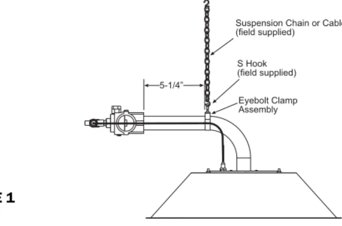
2. Attach a suspension chain (field supplied) or cable with S hooks to the brooder as shown below. Adjust the eyebolt clamp assembly to dimension shown. Slight adjustments can be made to achieve the required mounting angle as described in section 6.
3. Squeeze the S Hooks closed around the eyebolts and chain with a pair of pliers.
5.
MINIMUM CLEARANCES TO COMBUSTIBLES
Minimum clearances to combustible materials shall be measured from the outer surface of the canopy as shown in the following table:
MINIMUM CLEARANCES TO COMBUSTIBLES
SIDES:
BELOW: ABOVE:
36” (915 mm)
42” (1068 mm)
17” (432 mm)
FIGURE 2 FIGURE 1
Suspension Chain or Cable (field supplied) 5-1/4 Eyebolt Clamp Assembly S Hook (field supplied) SIDE SIDE ABOVE BELOW
6. BROODER
INSTALLATION
1. Locate brooders as needed for animal comfort and building heat loss. If more than one row is desired, stagger rows for best heat distribution.
2. Suspend the brooder at the desired height above the floor (litter) level, normally 48 to 60 inches (1220mm to 1520mm). For brooders connected to a winch (to allow for adjustment of brooder height), connect each brooder using a chain or cable suitable for the weight of each brooder. DO NOTUSE ROPE. Size the winch and cable so that it is capable of handling the total weight of all brooders and gas piping involved. NOTE: Connect a safety chain to each brooder and anchor it to the house structure above each brooder to prevent it from falling onto the litter if the cable/chain breaks or the winch fails. THE GAS HOSE SHOULD NEVER BE USED AS A SAFETY CHAIN!
3. Connect the gas line and electrical supply (if required) to each brooder as outlined in Sections 7 and 8. After connection of the gas line, make sure that the brooder is suspended with an angle of approximately 1 1/2 to 3° as shown in figure 3 to prevent hot products of combustion from damaging the gas control valve.
SCAUTION: CHECK THAT THE ANGLE IS CORRECT AFTER THE GAS HOSE IS INSTALLED DUE TO ADDITIONAL WEIGHT! ANGLE MOUNTING GREATER THAN 3°MAY CAUSE IMPROPER FLAME PATTERN AND NUISSANCE OUTAGES!
WARNING
FIRE HAZARD
A safety chain must be connected from the hanging bracket to a fixed part of the building structure directly above the brooder.
The safety chain will prevent the brooder from falling to the floor in the event that the main suspension system fails
Failure to follow these instructions may result in death, serious injury or property damage
!
FIGURE 3 Ceiling Structure 3° Safety chain or cable attached to house ceiling structure. (provide 2 to 6 of slack) Suspension chain orcable attached to winch system.
7. GAS
CONNECTIONS
1. Gas piping for the house must be sized to be capable of satisfying the entire demands of the house should all equipment be operating at the same time. Please use the National Fuel Gas Code for the sizing of piping for the house.
2. Connect to the supply tank or manifold in accordance with the latest edition of the National Fuel Gas Code (ANSI Z223.1) and/or local codes. Authorities having jurisdiction should be consulted before the installation is made. Refer to the latest edition of CAN/CGA B.149-1/2 Installation Codes for Gas Burning Appliances and Equipment in Canada.
3. Pipe joint compounds must be resistant to the action of liquefied petroleum (LP) gases.
4. The SHP17B brooders are intended to be used with a regulated supply pressure at 5PSIG for maximum heat input and control system to delivery 10” w.c. for minimum heat input. See accessories for control panels.
4. Gas connections to individual brooders can be made in several ways to fit individual operation practices. Brooders can be installed with flexible gas connectors, or they can utilize rubber hosing suitable for LP gas usage (to allow movement of the brooders for cleaning, etc.). Check with the authorities having jurisdiction and/or local codes prior to choosing an individual gas connection method. See below for optional connection methods:
4.1. Connection to replace an existing brooder with left hand thread inlet connections. The SHP17B connection is a 1/8” NPT right handed thread. There is an adaptor PN 30714990 supplied with each brooder to convert to the Left hand thread connection.
Screw the adaptor onto the brooder first. Use a wrench to tighten the joint securely. To connect to an existing Left hand thread hose, the adaptor must be held securely with a wrench so that the action of tightening the hose does not loosen the adaptor to the brooder connection.
FIGURE 4
Apply LP and Natural Gas approved thread sealant
1/8 NPT (right hand thread) PN 30714990 LH thread adaptor
4.2. Connection to a new installation with accessory Quick Connect hose kit PN 30522250. (the kit is available as an accessory and must be ordered separately) Is shown below:
Item Number Part Number Description Qty
1 30285000 VALVE,MANUAL BALL 1/2" 1
2 03338100 BUSHING,1/2X 1/4 GALV 1
3 03331020 NIPPLE,1/4X CLOSE(GAL) 1
4 30720010 QUICK DISCONNECT 1/4"HI PRESS QC x1/4F NPT 1
5 30523260 HOSE,1/4IDx6FT W/250 PLUG x 3/8"F SWIVL 1
6 30630020 FEMALE FTG 45FLARE 3/8TUBEx1/8FPT 1
The quick connect coupling assembly is shown below. Make sure connection is secure before turning on the gas. See section 8 for procedures to test for gas leaks before putting the brooders into operation.
Pull Collar back firmly. Insert male
fitting until fully engaged.
5. It is strongly recommended that a field installed manual shut-off valve be installed in the gas piping to each brooder. The shut off valve is included with the Quick Connect hose kit PN 30522250. This will allow service of individual brooders without having to shut down the entire gas supply system. When installing the gas line, it is recommended to connect a sediment trap (see figure 7) in the gas line at a point before the gas line enters the house. This trap or “drip leg” acts to trap impurities and water that can condense out of the gas. It helps to keep impurities from entering the appliance and causing potential damage to gas valves, etc. Periodically remove the cap from the drip leg and drain any accumulation of dirt and/or water.
FIGURE 5 FIGURE 6 To Brooders Gas Supply Inlet Tee Fitting Pipe Nipple Pipe Cap 3 Minimum SEDIMENT TRAP (DRIP LEG) FIGURE 7
1
2 3 4
5
6
6. After all gas connections and adjustments are made, check all gas connections for leaks (not just the gas connections at the brooders) using a heavy soap suds solution or by using one of the methods listed in Appendix D of the National Fuel Gas Code. SWARNING: DO NOT USE AN OPEN FLAME OF ANY KIND TO TEST FOR LEAKS!
7. It is recommended that a pressure gauge be installed at the end of the gas piping run to allow you to check the gas supply pressure in the system. This needs to be capable of accurately measuring in units of inches of water column or mbar for low pressure operation and psig for high pressure operation.
8. INSTRUCTIONS FOR TESTING FOR GAS LEAKS AND PROPER GAS
PRESSURE
SWARNING: DO NOT OMIT THESE TESTS! TESTING THE INSTALLATION FOR GAS LEAKS:
1. Inspect all connections and appliance valves to be sure connections are wrench-tight and that all appliance valves are closed, including the pilot valves.
2. Connect a high-pressure test set to the piping system just upstream of the brooder.
3. Fully open the LP gas container valve slowly to pressurize the piping system. Once the system is pressurized and stabilized, close the container valve tightly.
4. Observe the indicated pressure on the test set gauge. This reading should be approximately equivalent to the set delivery pressure of the final stage regulator. Now, slowly open one burner valve or pilot valve on the appliance to vent off just enough gas to reduce the pressure on the test gauge by 1 in. water column, then close the burner or pilot valve.
If the pressure remains unchanged on the gauge for at least 10 minutes, the system can be assumed leak-tight. If a drop in pressure does occur, it indicates a leak in the system.
If the pressure drop occurs, check the joints, connectors, and other possible points of leakage with an approved, high quality leak detection solution. NEVER USE A MATCH OR OPEN FLAME TO CHECK FOR LEAKS. Once a leak has been located and repaired, repeat Steps 3 and 4 above. If there is an increase in pressure, it indicates that the LP gas container valve is not shut off tightly. Shut off the valve tightly and repeat Step 4 above.
NOTE: Do not expose final stage piping to excessive heat or direct sunshine during the leak test. Pressure build-up in the line due to heat may compensate for pressure loss due to leaks. This will prevent the gauge reading from indicating system leaks.
SWARNING: Gas Pressure Testing is to be performed only by qualified personnel. CHECK GAS INLET (SUPPLY) PRESSURE:
1. Be sure the shut off valve is in the “OFF” position before disconnecting the hose. Connect a suitable high pressure gauge as shown below at the furthest brooder from the second stage regulator (or control panel). Turn the shut off valve to the “ON” position and light the brooders with the thermostat set to the highest temperature to give maximum gas pressure. DO NOT EXCEED 5PSI INLET PRESSURE TO THE BROODER.
FIGURE 8
1/8 x 1/8 x 1/8 NPT TEE
0-10 PSIG GAUGE 1/8 x 1/8 NIPPLE
2. Turn the shut off valve back to the “OFF” position before removing the test set and replacing the plug. Repeat the gas leak test at the plug.
GAS PRESSURE TABLE
SUPPLY PRESSURE
BROODER MODEL GAS TYPE REGULATOR PRESSURE Minimum Maximum
SHP17B-L6 Propane Gas 5 PSIG to 10” w.c. 10”WC (25 mbar) 5 psig (350 mbar)
SHP17B-N6 Natural Gas 5 PSIG to 10” w.c. 10”WC (25 mbar) 5 psig (350 mbar) Minimum permissible gas supply pressure for the low fire operation of the brooder.
REGULATOR LOCK-UP AND LEAKAGE:
After the leak testing and delivery pressure tests have proven satisfactory, the regulator lock-up and leakage test may be performed. The lock-up pressure of the final stage regulator should be slightly higher than, but not more than, 120% of the set delivery pressure. For example, on a delivery pressure setting of 5 PSIG, the maximum allowable lock-up pressure is 6 PSIG.
To perform the lock-up and leakage test, follow these steps:
1. With the LP tank valve fully open, shut off all appliance valves so there is no demand for gas. This includes shutting off all pilots.
2. A slight rise in pressure will occur under these conditions. This rise should be no more than 120% of the delivery pressure. This is the lock up pressure. NOTE: A quick rise in pressure above the allowable lock-up point could indicate undersized piping, a worn seat disc or foreign material in the seating area. This condition must be corrected before putting the system in service.
3. Continue the test for five minutes or more. If a creeping rise in pressure is noticed, the final stage regulator seat is not closing off properly. The regulator must be replaced or repaired, and the system retested, before putting the system in service.
9.
LIGHTING AND SHUTDOWN INSTRUCTIONS
1. Turn on the gas supply at Maximum pressure. If the pressure is controlled by a
thermostatic device, set to the maximum temperature to obtain the fully open
position
2. Push and hold down the button on the safety valve. Immediately light the gas at
the emitter with a flame that will allow you to keep a safe distance from your
hand. Continue to hold the button down for about one (1) minute after the
brooder is lit. If it goes out, wait five (5) minutes before trying to relight the pilot.
NOTE: If the button does not pop up when released, stop and immediately call
your service technician or gas supplier.
3. If the burner will not stay lit after several tries, turn off the gas and call your
service technician or gas supplier.
4. When the burner flame remains lit, adjust the thermostatic control to the
desired temperature.
5. To turn off the brooders shut off the gas supply valves.
6. Allow the gas to be burnt off by the brooder. When the brooder flame is
extinguished all gas is expelled from the system.
10. VENTILATION
FOR YOUR SAFETY: Exhaust fans must be operating on an appropriate cycle when heating the building to avoid high concentrations of carbon monoxide and water vapor.
SWARNING: Carbon Monoxide is an odorless and poisonous gas. Extended exposure to carbon monoxide may lead to death. Early signs of carbon monoxide poisoning resemble the flu, including headaches, dizziness and/or nausea. If you experience these signs, GET FRESH AIR IMMEDIATELY. Have the brooders serviced as soon as possible and check the ventilation in the house.
The National Fuel Gas Code requires a minimum of 4 CFM per 1000 Btu/hr of brooder input for ventilation. This requirement means that a total of 68 CFM is required per brooder. Ventilation requirements may vary depending on other equipment that may be located in the building requiring ventilation. All ventilation requirements should be addressed before sizing the necessary gravity or mechanical means to accomplish this ventilation.
While ventilation is necessary for proper brooder operation and proper growing conditions for the stock, excessive ventilation can result in high fuel consumption. Adjust the ventilation as necessary for optimum performance of the brooders and growing conditions for the stock.
11. MAINTENANCE
To keep your brooder in good operating condition, we recommend that after each crop you follow the maintenance schedule below:
!CAUTION:
TURN THE GAS AND ELECTRIC (IF EQUIPPED) SUPPLIES OFF AND ALLOW THE BROODER TO COOL DOWN BEFORE ATTEMPTING ANY MAINTENANCE.
1. Disassemble the burner assembly as shown below:
1. Unscrew thermocouple
2. Unscrew M5 set screw
2. Set the burner assembly to one side and use compressed air or a blower depending on the amount of dirt to be removed on the emitter assembly.
3. It is recommended to clean the orifice only when there are signs that the orifice is blocked. See the trouble shooting section for more details. To clean the orifice, first remove it from the orifice fitting. Unscrew the main burner orifice from the orifice fitting using a 9/16” or 14mm extended socket and clean the orifice by soaking it in acetone. Dry the orifice by blowing compressed air through it. NOTE: DO NOT attempt to clean the orifice by passing a wire through the orifice as this will increase the orifice hole and result in over firing of the emitter.
FIGURE 9
FIGURE 10
4. Apply pipe thread sealant (resistant to LP Gas) to the threads of the orifice and replace it into the orifice fitting. Re-connect the burner assembly to the brooder in reverse order.
Filters must be cleaned every 2 to 6 days.
Failure to do so may result in soot formation or illness from Carbon Monoxide poisoning.
CARBON MONOXIDE HAZARD
5. Clean the air filters (furnished as accessories) when they become clogged with dust and
debris. Remove both filters from the brooder as shown. Blow compressed air through the openings until filters are clean. NOTE: DO NOT attempt to clean the filters using a wire brush as this will damage them.
NOTE: After reassembly of all components, check the gas connections at the burner and the gas valve for leaks. Use a heavy soapsuds solution. DO NOT use an open flame to check for gas leaks. See section 8 for leak checking instructions.
1. Unscrew M5 set screws
and remove air filters.
Air Filter
12. TROUBLESHOOTING
TROUBLE POSSIBLE CAUSE SOLUTIONS
Burner will not stay lit when lighting…
There is air in the gas line. The orifice is clogged.
The thermocouple is defective. The safety valve is defective. The air filters are dirty and clogged.
Bleed the air out or continue to ignite the brooder until all the air is purged.
Remove and clean the orifice as necessary. Replace the thermocouple.
Replace the gas valve.
Remove and clean the air filters.
Brooder shuts off on low flame (i.e. minimum gas pressure)…
The primary orifice is clogged. The gas supply pressure is insufficient. The thermocouple is inserted too far into
the brooder.
The thermocouple is defective. The brooder angle is too steep. The safety valve is defective. The air filters are dirty and clogged.
Remove and clean the orifice as necessary. Check the manifold gas pressure and
adjust as necessary. Replace the thermocouple.
Adjust the thermocouple depth to 0.5” Adjust the brooder angle to 1 ½ to 3
degrees.
Replace the gas valve.
Remove and clean the air filters.
Brooder is not glowing red…
The supply gas pressure is too low. The gas piping size is incorrect. The orifice is clogged.
The orifice size is incorrect.
Check the manifold gas pressure and adjust as necessary.
If you are not sure of the performance, use the NFPA 54 gas pipe sizing table in this manual.
Remove and clean the orifice as necessary. See the instructions for correct orifice size
and replace if necessary.
Brooder will not attain the desired temperature…
There is insufficient heat in the building for heat loss (i.e., not enough brooders). The thermostat sensing bulb is incorrectly
placed.
The thermostat is out of calibration.
Conduct a heat loss and add brooders or other source of heat as necessary. Reposition the sensing bulb as necessary
for proper operation. NOTE: The sensing bulb should be shielded from direct radiation to prevent short cycling of the brooder.
Recalibrate (if possible) or replace.
Flames flaring up, outside of emitter surface…
The gas pressure is too high. The brooder is dirty
The orifice size is incorrect.
The type of gas supplied to the brooder is incorrect.
There is insufficient combustion air. The air filters are dirty and clogged.
Check the manifold gas pressure and adjust if necessary.
Clean brooder.
See instructions for correct orifice size and replace if necessary.
Check the nameplate to identify the correct type of gas the brooder is equipped to operate using.
Clean the inside of the burner with a wire brush and blow out with compressed air. Remove and clean the air filters
13. REPLACEMENT PARTS GUIDE
Item No. Part No. Description
1 30723000 Stainless Steel Canopy 2 30724000 Emitter Assembly 3 02333000 Screw M5 x 10
3a 02335000 Eyebolt M6 x 20 x 10mm 3b 30747000 Suspension Clamp 28-32mm
4 30725100 Orifice Holder/Air Injector 4a 30745000 Filter Casing
4b 30744000 Air Filter
5 30726000 Bypass Valve Assembly 6 30727000 Thermocouple M8 x 450 6a 30728000 Thermocouple Nut M8 x 1
7 30729000 Safety Valve
8 30746000 Primary Orifice – Propane Gas (0.50mm) 8a 30746010 Primary Orifice – Nat Gas (0.60mm) 8b 02336000 O-Ring 2.0mm x 1.0mm
9 02323000 Washer M4
9a 02324000 Nut M4
10 30732050 Venturi 30 x 71.2 x 18mm – Propane Gas (shown) 10a 30732060 Venturi 30 x 71.2 x 12mm – Nat Gas
11 30734000 Nipple 1/8” x 1/8”
Screws, nuts and washers are standard hardware items and can be purchased at any local hardware store.
ALL ILLUSTRATIONS ARE INTENDED TO GIVE THE GENERAL IMPRESSION OF UNITS ONLY. WE RESERVE THE RIGHT TO ALTER ANY SPECIFICATION WITHOUT NOTICE.
FIGURE 12 Primary Orifice
1
2
10, 10a
5
6
6a
7
4
8, 8a, 8b
8, 8a
11
9a (4 ea.)
9 (4 ea.)
4b
3
3
4a
4b
3a, 3b
GAS-FIRED PRODUCTS LIMITED WARRANTY LIMITED WARRANTY
Gas-Fired Products, Inc. (GFP), the manufacturer, warrants the original owner of any Space-Ray Poultry Heating Product that it will be free from defects in material or workmanship under normal use and service. The heater(s) shall be installed, used and maintained strictly in accordance with the manufacturer's instructions. The manufacturer's sole obligation under this warranty is limited to furnishing replacement parts, F.O.B. Charlotte, NC, for 12 months from the date of installation, or 18 months from the date of shipment by the manufacturer, whichever period expires first. Labor charges for the removal of defective parts or the installation of replacement parts are not included.
WARNING: Manufacturer's warranty shall not apply: (a) to circumstances where gas pressure to each heater is higher than that specified for each heater; (b) to circumstances where the type of gas is different than the type of gas noted on the name plate for each heater; (c) to water damage to gas controls; and (d) to any heater or component which has been repaired or replaced with other than factory parts, modified in any way, misused or damaged, or which has been used contrary to the manufacturer's written instructions.
LIMITATION OF WARRANTY: THERE ARE NO WARRANTIES, EXPRESS OR IMPLIED,
WHICH EXTEND BEYOND THE DESCRIPTION ON THE FACE HEREOF. WITHOUT LIMITING THE FOREGOING, THE MANUFACTURER EXPRESSLY EXCLUDES ANY AND ALL IMPLIED WARRANTIES, INCLUDING BUT NOT LIMITED TO ANY IMPLIED WARRANTY OF FITNESS FOR A PARTICULAR PURPOSE AND ANY IMPLIED WARRANTY OF MERCHANTABILITY FOR ITS PRODUCTS.
If any provision of this warranty is found to be void, unenforceable or unconscionable, then that portion is hereby severed and the remainder of this warranty is hereby saved and shall remain in force.
EXCLUSIVE REMEDY: The sole and exclusive remedy under this warranty is the replacement of the defective parts or brooders as hereinabove specified. THE MANUFACTURER DOES HEREBY EXPRESSLY EXCLUDE ANY AND ALL LIABILITY FOR INCIDENTAL OR CONSEQUENTIAL DAMAGES UNDER THIS OR ANY OTHER WARRANTY. Without intending to limit the aforesaid exclusion, THE MANUFACTURER DOES HEREBY EXCLUDE ANY LIABILITY UNDER THIS OR ANY OTHER WARRANTY FOR INJURIES OR COMMERCIAL LOSSES TO PROPERTY THAT RESULT FROM THE OPERATION, PROPER OR IMPROPER, OF ITS PRODUCTS.
ADDITIONAL TERMS: Manufacturer assumes no liability for delay in performing its obligations under this warranty. Manufacturer assumes no liability for failure in performing its obligations there under if failure results directly or indirectly from any cause beyond its control, including but not limited to acts of God, acts of Government, floods, fires, shortages of materials, strikes and other labor difficulties or delays or failures of transportation facilities.
This is a Non-Residential product. Installation and service shall be by a Licensed Contractor and in accordance with National and Local Codes.
When presenting warranty claims, proof of date of purchase must be submitted.
No Representative is authorized to assume for the manufacturer, any liability except as set forth above.
For the name of your nearest distributor in case of claim under this warranty, contact: Space-Ray / Gas-Fired Products, Inc. / 305 Doggett St., PO Box 36485 / Charlotte, NC 28236 / Phone: (704) 372-3485 / Fax: (704) 332-5843 / email: info@spaceray.com.
FOR YOUR RECORDS:
Space-Ray Brooder Model Number: Date Installed: Serial Numbers:
For replacement parts, please contact your local distributor or:
SPACE-RAY
305 Doggett Street Charlotte, NC 28203-4923