IBM Networking OS
Release Notes
Note: Before using this information and the product it supports, read the general information in the Safety information and
Environmental Notices and User Guide documents on the IBM Documentation CD and the Warranty Information document that comes with the product.
First Edition (May 2012)
© Copyright IBM Corporation 2012
US Government Users Restricted Rights – Use, duplication or disclosure restricted by GSA ADP Schedule Contract with IBM Corp.
Release Notes
This release supplement provides the latest information regarding IBM
Networking OS 7.2 for the EN2092 1Gb Ethernet Scalable Switch (referred to as EN2092 throughout this document).
This supplement modifies and extends the following IBM Networking OS documentation for use with Networking OS 7.2:
• IBM Networking OS Application Guide for the IBM Flex System EN2092 1Gb Ethernet Scalable Switch
• IBM Networking OS Command Reference for the IBM Flex System EN2092 1Gb Ethernet Scalable Switch
• IBM Networking OS ISCLI Reference for the IBM Flex System EN2092 1Gb Ethernet Scalable Switch
• IBM Networking OS BBI Quick Guide for the IBM Flex System EN2092 1Gb Ethernet Scalable Switch
• IBM Flex System EN2092 1Gb Ethernet Scalable SwitchUser’s Guide The publications listed above are available at the following address:
http://publib.boulder.ibm.com/infocenter/flexsys/information/index.jsp
Hardware Support
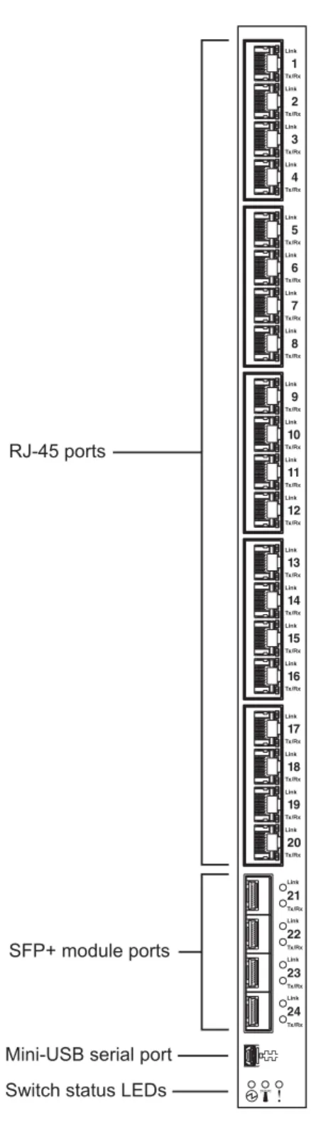
Networking OS 7.2 software is supported only on the IBM Flex System EN2092 1Gb Ethernet Scalable Switch for the IBM Flex System. The EN2092 1Gb Ethernet Scalable Switch (EN2092), shown in Figure 1, is a high performance Layer 2-3 embedded network switch that features tight integration with IBM Flex System chassis management module.
The EN2092 has the following port capacities: • Twenty 1Gb RJ-45 ports
• Four 10Gb SFP+ ports
• Twenty-Eight 1Gb internal ports (maximum) • One 1Gb internal management port
• One mini-USB serial port
Transceivers
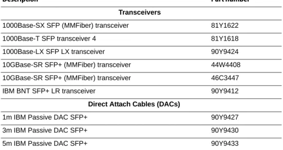
The following transceivers and DACs are available: Table 1. EN2092 Transceivers and DACs
Description Part number
Transceivers
1000Base-SX SFP (MMFiber) transceiver 81Y1622
1000Base-T SFP transceiver 4 81Y1618
1000Base-LX SFP LX transceiver 90Y9424
10GBase-SR SFP+ (MMFiber) transceiver 44W4408 10GBase-SR SFP+ (MMFiber) transceiver 46C3447
IBM BNT SFP+ LR transceiver 90Y9412
Direct Attach Cables (DACs)
1m IBM Passive DAC SFP+ 90Y9427
3m IBM Passive DAC SFP+ 90Y9430
Updating the Switch Software Image
The switch software image is the executable code running on the EN2092. A version of the image comes pre-installed on the device. As new versions of the image are released, you can upgrade the software running on your switch. To get the latest version of software supported for your EN2092, go to the following website:
http://www.ibm.com/systems/support
To determine the software version currently used on the switch, use the following switch command:
The typical upgrade process for the software image consists of the following steps: • Load a new software image and boot image onto an FTP or TFTP server on your
network.
• Transfer the new images to your switch.
• Specify the new software image as the one which will be loaded into switch memory the next time a switch reset occurs.
• Reset the switch.
For instructions on the typical upgrade process using the CLI, ISCLI, or BBI, see
“Loading New Software to Your Switch” on page 6.
ATTENTION: Although the typical upgrade process is all that is necessary in most cases, upgrading from (or reverting to) some versions of Networking OS requires special steps prior to or after the software installation process. Please be sure to follow all applicable instructions in the following sections to ensure that your switch continues to operate as expected after installing new software.
Loading New Software to Your Switch
The EN2092 can store up to two different switch software images (called image1
and image2) as well as special boot software (called boot). When you load new software, you must specify where it should be placed: either into image1, image2, or boot.
For example, if your active image is currently loaded into image1, you would probably load the new image software into image2. This lets you test the new software and reload the original active image (stored in image1), if needed.
ATTENTION: When you upgrade the switch software image, always load the new boot image and the new software image before you reset the switch. If you do not load a new boot image, your switch might not boot properly (To recover, see
“Recovering from a Failed Software Upgrade” on page 11).
To load a new software image to your switch, you will need the following:
• The image and boot software loaded on an FTP or TFTP server on your network. Note: Be sure to download both the new boot file and the new image file. • The hostname or IP address of the FTP or TFTP server
Note: The DNS parameters must be configured if specifying hostnames. • The name of the new software image or boot file
When the software requirements are met, use one of the following procedures to download the new software to your switch. You can use the Networking OS CLI, the ISCLI, or the BBI to download and activate new software.
Loading Software via the Networking OS CLI
1. Enter the following Boot Options command:
2. Enter the name of the switch software to be replaced:
3. Enter the hostname or IP address of the FTP or TFTP server.
4. Enter the name of the new software file on the server.
The exact form of the name will vary by server. However, the file location is normally relative to the FTP or TFTP directory (usually /tftpboot). 5. Enter your username for the server, if applicable.
If entering an FTP server username, you will also be prompted for the password. The system then prompts you to confirm your request. Once confirmed, the software will load into the switch.
6. If software is loaded into a different image than the one most recently booted, the system will prompt you whether you wish to run the new image at next boot. Otherwise, you can enter the following command at the BootOptions#
prompt:
The system then informs you of which software image (image1 or image2) is currently set to be loaded at the next reset, and prompts you to enter a new choice:
Specify the image that contains the newly loaded software. 7. Reboot the switch to run the new software:
The system prompts you to confirm your request. Once confirmed, the switch will reboot to use the new software.
>> # /boot/gtimg
Enter name of switch software image to be replaced ["image1"/"image2"/"boot"]: <image>
Enter hostname or IP address of FTP/TFTP server: <hostname or IP address>
Enter name of file on FTP/TFTP server: <filename>
Enter username for FTP server or hit return for TFTP server: {<username>|<Enter>}
Boot Options# image
Currently set to use switch software "image1" on next reset. Specify new image to use on next reset ["image1"/"image2"]:
Loading Software via the ISCLI
1. In Privileged EXEC mode, enter the following command:
2. Enter the hostname or IP address of the FTP or TFTP server.
3. Enter the name of the new software file on the server.
The exact form of the name will vary by server. However, the file location is normally relative to the FTP or TFTP directory (for example, tftpboot). 4. If required by the FTP or TFTP server, enter the appropriate username and
password.
5. The switch will prompt you to confirm your request.
Once confirmed, the software will begin loading into the switch.
6. When loading is complete, use the following commands to enter Global Configuration mode to select which software image (image1 or image2) you want to run in switch memory for the next reboot:
The system will then verify which image is set to be loaded at the next reset:
7. Reboot the switch to run the new software:
The system prompts you to confirm your request. Once confirmed, the switch will reboot to use the new software.
Loading Software via BBI
You can use the Browser-Based Interface to load software onto the EN2092. The software image to load can reside in one of the following locations:
• FTP server • TFTP server • Local computer
After you log onto the BBI, perform the following steps to load a software image: 1. Click the Configure context tab in the toolbar.
2. In the Navigation Window, select System > Config/Image Control. The Switch Image and Configuration Management page appears.
Router# copy {tftp|ftp} {image1|image2|boot-image}
Address or name of remote host: <name or IP address>
Source file name: <filename>
Router# configure terminal
Router(config)# boot image {image1|image2}
Next boot will use switch software image1 instead of image2.
3. If you are loading software from your computer (HTTP client), skip this step and go to the next. Otherwise, if you are loading software from a FTP/TFTP server, enter the server’s information in the FTP/TFTP Settings section.
4. In the Image Settings section, select the image version you want to replace (Image for Transfer).
– If you are loading software from a FTP/TFTP server, enter the file name and click Get Image.
– If you are loading software from your computer, click Browse.
In the File Upload Dialog, select the file and click OK. Then click Download via Browser.
Software Features
The following list summarizes the software features available with
Networking OS 7.2 for the IBM Flex System EN2092 1Gb Ethernet Scalable Switch (EN2092). For more detailed information about configuring EN2092 features and capabilities, refer to thecomplete Networking OS 7.2 documentation listed on
page 3. • Security
– Secure interface login and password – RADIUS and TACACS+
– SSH v2
– HTTPS secure Browser-Based Interface
– Wire-speed filtering with Access Control Lists (ACLs) • Layer 2
– 1024 VLANs (802.1Q), including Private VLANs – Multi-link trunking, compatible with Cisco EtherChannel – LACP (IEEE 802.3ad)
– Per VLAN Rapid Spanning Tree (PVRST), Per VLAN Rapid Spanning Tree Plus (PVRST+), Multiple Spanning Tree (802.1s), Rapid Spanning Tree (802.1w), with Fast Uplink Convergence
– 32 K forwarding database entries • Layer 3
– Dynamic routing – RIP v1, v2 – OSPF – BGP
– 128 configurable interfaces (static or DHCP) – DHCP Relay
– IP forwarding
– IGMP Snooping v1, v2, v3 – 4 K ARP entries
– IPv6 host management • Quality of service
– 802.1p priority queues
– Differentiated Services Code Point (DSCP) support • Availability
– Layer 2 failover – Hot links – VRRP • Virtualization
Supplemental Information
This section provides additional information about configuring and operating the EN2092 and Networking OS.
The Boot Management Menu
The Boot Management menu allows you to switch the software image, reset the switch to factory defaults, or to recover from a failed software download.
You can interrupt the boot process and enter the Boot Management menu from the serial console port. When the system displays Memory Test, press <Shift B>. The Boot Management menu appears.
The Boot Management menu allows you to perform the following actions: • To change the booting image, press 1 and follow the screen prompts. • To change the configuration block, press 2, and follow the screen prompts. • To perform a software image recovery, press 3 and follow the screen prompts. • To perform an Xmodem download (boot image only), press 4 and follow the
screen prompts.
• To exit the Boot Management menu, press 6. The booting process continues.
Recovering from a Failed Software Upgrade
Use the following procedure to recover from a failed software upgrade. 1. Connect a PC to the serial port of the switch.
2. Open a terminal emulator program that supports Xmodem download (for example, HyperTerminal, CRT, PuTTY) and select the following serial port characteristics:
– Speed: 9600 bps – Data Bits: 8
– Stop Bits: 1 – Parity: None – Flow Control: None
Resetting the System ...
Memory Test ... 1 - Change booting image
2 - Change configuration block
3 - Boot in recovery mode (tftp and xmodem download of images to recover switch)
4 - Xmodem download (for boot image only - use recovery mode for application images)
5 - Reboot 6 - Exit
4. Select 3 for Boot in recovery mode. You will see the following display:
– If you choose option x (Xmodem serial download), go to step 5. – If you choose option t (TFTP download), go to step 6.
5. Xmodem download: When you see the following message, change the Serial Port characteristics to 115200 bps:
a. Press <Enter> to set the system into download accept mode. When the readiness meter displays (a series of “C” characters), start XModem on your terminal emulator.
b. When you see the following message, change the Serial Port characteristics to 9600 bps:
c. When you see the following prompt, enter the image number where you want to install the new software and press <Enter>.
d. The following message is displayed when the image download is complete. Continue to step 7.
6. TFTP download: The switch prompts you to enter the following information: Entering Rescue Mode.
Please select one of the following options:
T) Configure networking and tftp download an image X) Use xmodem 1K to serial download an image R) Reboot
E) Exit
Change the baud rate to 115200 bps and hit the <ENTER> key before initiating the download.
Change the baud rate back to 9600 bps, hit the <ESC> key.
Install image as image 1 or 2 (hit return to just boot image): 1
Installing image as image1... Image1 updated successfully
Please select one of the following options:
T) Configure networking and tftp download an image X) Use xmodem 1K to serial download an image R) Reboot
E) Exit
Performing TFTP rescue. Please answer the following questions (enter 'q' to quit):
IP addr : Server addr: Netmask : Gateway : Image Filename:
a. Enter the required information and press <Enter>. b. You will see a display similar to the following:
c. When you see the following prompt, enter the image number where you want to install the new software and press <Enter>.
d. The following message is displayed when the image download is complete. Continue to step 7.
7. Image recovery is complete. Perform one of the following steps: – Press r to reboot the switch.
– Press e to exit the Boot Management menu
– Press the Escape key (<Esc>) to re-display the Boot Management menu.
Recovering a Failed Boot Image
Use the following procedure to recover from a failed boot image upgrade. 1. Connect a PC to the serial port of the switch.
2. Open a terminal emulator program that supports Xmodem download (for example, HyperTerminal, CRT, PuTTY) and select the following serial port characteristics:
– Speed: 9600 bps – Data Bits: 8
– Stop Bits: 1 – Parity: None – Flow Control: None
3. Boot the switch and access the Boot Management menu by pressing <Shift B> while the Memory Test is in progress and the dots are being displayed. 4. Select 4 for Xmodem download. You will see the following display:
Host IP : 10.10.98.110 Server IP : 10.10.98.100 Netmask : 255.255.255.0 Broadcast : 10.10.98.255 Gateway : 10.10.98.254
Installing image 6.8.3_OS.img from TFTP server 10.10.98.100
Install image as image 1 or 2 (hit return to just boot image): 1
Installing image as image1... Image1 updated successfully
Please select one of the following options:
T) Configure networking and tftp download an image X) Use xmodem 1K to serial download an image R) Reboot
5. When you see the following message, change the Serial Port characteristics to 115200 bps:
a. Press <Enter> to set the system into download accept mode. When the readiness meter displays (a series of “C” characters), start Xmodem on your terminal emulator.You will see a display similar to the following:
b. When you see the following message, change the Serial Port characteristics to 9600 bps:
Boot image recovery is complete.
Chassis Management Module
When configuring the IP interface, which is dedicated to the internal management port (IF128, MGT1), you cannot use a subnet that is already configured on any other enabled interface (IF1-126). This results in port MGT1 not accepting the
configuration and an IP configuration of all zeros displayed on the CMM user interface.
For example, consider that an external interface (IF1) is configured or enabled to the following IP address and mask:
The switch will reject an attempt made from the CMM CLI to configure the internal management port (MGT1, IF128) to the following IP address and mask:
In this scenario, the switch rejects the attempt by disabling any current configuration on IF128, and responds to the CMM with an IP address, mask, and gateway that contains all zeros.
Change the baud rate to 115200 bps and hit the <ENTER> key before initiating the download.
Extracting images ... Do *NOT* power cycle the switch. **** RAMDISK ****
Un-Protected 38 sectors Erasing Flash...
... done Erased 38 sectors
Writing to
Flash...9....8....7....6....5....4....3....2....1....done Protected 38 sectors
**** KERNEL **** Un-Protected 24 sectors Erasing Flash...
... done Erased 24 sectors
Writing to Flash...9....8....7....6....5....4....3....2....1....
Change the baud rate back to 9600 bps, hit the <ESC> key.
Interface information:
1: IP4 192.168.71.120 255.255.255.0
On the CMM CLI, the resulting condition appears as follows:
External Port Link Negotiation
Autonegotiation settings for each external switch port should be the same as those of the devices being connected. In a valid configuration, both ends of a port link are set with autonegotiation on, or both ends are set to specific speed and link
properties with autonegotiation disabled.
Port Mirroring Tags BPDU Packets
When you perform port mirroring, Spanning Tree BPDU packets are VLAN tagged at the monitoring port. This is standard behavior of port mirroring on the EN2092. All mirrored egress traffic is tagged.
Secure Management Network
The following EN2092 attributes are reserved to provide secure management access to and from the chassis management module:
• MGT port • VLAN 4095
• IP interface 127, 128 • Gateway 4
• STG 128
For more information about remotely managing the EN2092 through the external ports, see “Accessing the Switch” in the IBM Networking OS 7.2 Application Guide. Note:The external uplink ports (EXTx) cannot be members of management
VLANs.
Secure Shell (SSH)
Because SSH key generation is CPU intensive, the EN2092 attempts to avoid unnecessary key generation. The process generates three server keys: 1. One key is generated to replace the current server key, if used.
2. A second key is generated as a spare, in case the current server key is used and the specified interval expires.
3. A third key is generated for use at the next reboot.
Therefore, if you never login via SSH, you will only see two key generation events. You may see all three events directly following a reboot. If you want to witness the key generation after the specified interval has expired, then you must login via SSH
system:switch[1]> ifconfig Ethernet ScSE
Enabled -c static -i 0.0.0.0 -s 0.0.0.0 -g 0.0.0.0
Spanning Tree Configuration Tips
To ensure proper operation with switches that use Cisco Per VLAN Spanning Tree (PVST+), you must do one of the following:
• Create a separate Spanning Tree Group for each VLAN.
• Manually add all associated VLANs into a single Spanning Tree Group. When using Layer 2 Trunk Failover, disable Spanning Tree Protocol on external ports.
Syslog Configuration Tip
The facility parameter traditionally is used to correlate services (such as IP, CLI, etc.) to messages. This is done to distinguish between the different services that are running in the network/device. However, for the EN2092, there is a single configured facility value (0-7) used on all messages. By configuring a unique facility value for each switch, a single SYSLOG server can distinguish between the various EN2092s in the network. Refer to “System Host Log Configuration” in the Command
Reference.
Trunk Group Configuration Tips
Please be aware of the following information when you configure trunk groups: • Always configure trunk groups first, on both ends, before you physically connect
the links.
• Configure all ports in a trunk group to the same speed (you cannot aggregate 1Gb ports with 10GBASE-SFP+ ports).
vCenter Synchronization
When applying distributed VM group configuration changes, the switch will attempt to synchronize settings with the VMware vCenter for virtualization management. If the vCenter is unavailable, an error message will be displayed on the switch. Be sure to evaluate all error message and take the appropriate actions to ensure the expected changes are properly applied. If corrective actions are not taken, synchronization may remain incomplete when connection with the vCenter is restored.
Solution: When the switch connection with the vCenter is restored, use the following operational command to force synchronization:
VRRP Configuration
Although the Virtual Router Redundancy Protocol (VRRP) standard permits up to 255 virtual router instances, the Networking OS 7.2 implementation only allows up to 128 virtual router instances (corresponding to the number of supported IP interfaces). Each virtual router instance can be assigned a unique Virtual Router ID (VRID) between 1 and 255.
Known Issues
This section describes known issues for Networking OS 7.2 on the IBM Flex System EN2092 1Gb Ethernet Scalable Switch.
Boot Configuration Block
In the CLI, the boot configuration command (/boot/conf<block>) examines only the initial character of the block option. Invalid block strings (those other than
active, backup, or factory) that use a valid first character (a, b, or f) will be interpreted as the matching valid string. (ID: 42422)
Hotlinks
Prior to enabling hotlinks, Spanning-Tree should be globally disabled using the following command (ID: 47917):
IPsec
• IPsec does not support virtual links. (ID: 48914)
ISCLI Configuration Scripts
When using the ISCLI, configuration commands are applied to the active switch configuration immediately upon execution. As a result, when using the ISCLI to load a configuration script containing a long list of processor-intensive commands (such as static route definitions), switch response to other management functions (such as Telnet access for additional management sessions) may be slow or even time-out while the switch individually applies each scripted command. (ID 31787)
Solution: The CLI may be used as an alternative to the ISCLI. Because CLI commands are not fully processed until the CLI apply command is given, the equivalent configuration script can be loaded in its entirety and then applied as a whole without undue impact on other management sessions.
Jumbo Frames
Some ingress jumbo frames (for example, ICMP) are not routed from one VLAN to another VLAN. Jumbo frames are routed across data VLANs.
LACP
• If a static trunk on a EN2092 is connected to another EN2092 with LACP configured (but no active LACP trunk), the /info/l2/trunk command might erroneously report the static trunk as forwarding.
• If you configure LACP (active/passive) on one port, also configure LACP on the partner switch, at the end of the link. If you connect LACP with a static trunk, there will be no connectivity on that link.
• Since LACP trunks use LACPDU packet to maintain trunking with the partner, Router(config)# spanning-tree mode dis
OSPF
• Some changes to OSPF configuration (such as creating a new area or changing an area’s type) may result in OSPF state reconvergence. (ID: 46445, 48483) • OSPFv3 over IPsec
– This combination can only be configured only on a per-interface basis. Configuration based on virtual links is not currently supported.
– The current implementation for OSPFv3 allows the use of only one protocol (AH or ESP) at any given time. AH and ESP cannot be applied together.
Ports and Transceivers
• Under repeated and rapid removal and reinsertion a port transceiver, it is possible that the resulting port state may not be represented accurately within the switch. (ID 32412)
Solution: Once you have removed a transceiver from a switch port, wait five seconds before reinserting any transceiver into the same port. This allows the port to stabilize, and promotes accurate port state information within the switch. • When the link speed for an external connection is forced (i.e. no
Auto-Negotiation) to 100 Mbps and then changed to 10 Mbps, if the external device is changed first, the external device may erroneously report the link as DOWN even after the switch is changed to 10 Mbps.
Solution: At the external device, disconnect and reconnect the cable. • Interoperability with Older Hubs
The command-line interface might display link up and link down messages continuously for an external port that is connected to certain older hub models configured for 100 Mbps half-duplex. The display might show link up
erroneously. This behavior has been observed when connecting the switch with the following devices:
– NETGEAR FE104 100 hub – SBS 1000Base-T NIC
– 3Com Linkbuilder FMS100 Hub 3C250 TX/I – 3Com SuperStack II 100TX 3C250C-TX-24/12 – Nortel Baystack 204 Hub
If the EN2092 is connected to an application switch which requires a link speed of 100 Mbps half-duplex, then enable auto negotiation on the EN2092 port with port speed=any, mode=any, fctl=both, and auto=on.