SL STRIP 400 TW LED Luminaires
About this Manual
Sh wline
PREFACE
1. About this Manual
The document provides installation and operation instructions for the following products:
Please read all instructions before installing or using this product.Retain this manual for future reference. Additional product information and descriptions may be found on the product specification sheet.
Note:The SL STRIP 400 TW LED Luminaire is universal voltage 100 to 240 VAC (auto-ranging).
2. Included Items
Each SL STRIP 400 TW LED Luminaire includes the following items:
Installation and User’s Manual(this document)
SL STRIP 400 TW LED Luminaire Accessories
SL STRIP 400 TW LED Luminaire Power Input Cables (North American Models Only)
SL STRIP 400 TW LED Luminaires3
SL STRIP 400 TW LED Luminaire (IP65 rated)
SL STRIP 400 TW LED Luminaire
PC1BE AC Power Input Cable 39 inches- ( /1 meter Powercon with Bare End), * (*Note user supplies and installs,
own AC input connector)
Part Number Description
PC1BE SL S RIT P 400TW LED Luminaire AC Power nput Cable ( 9 inches / 1 meter),I 3 Powerconwith Bare End* (*Note user supplies and installs own AC input connector, )
PC1GP SL S RIT P 400TW LED Luminaire AC Power nput Cable ( 9 inches / 1 meter),I 3 Powerconwith Stagepin Connector
PC1GTL SL S RIT P 400TW LED Luminaire AC Power nput Cable ( 9 inches / 1 meter),I 3 Powerconwith Twistlock Connector
PC1GR SL S RIT P 400TW LED Luminaire AC Power nput Cable ( 9 inches / 1 meter),I 3 Powerconwith Edison Connector
PC3BE SL S RIT P 400TW LED Luminaire AC Power nput Cable ( .8I 9 Feet /3 meter), Powerconwith Bare End* (*Note user supplies and installs own AC input connector, )
PC8BE SL S RIT P 400TW LED Luminaire AC Power nput Cable ( 6 F et /I 2 e 8 meter), Powercon withBare End* (*Note user supplies and installs own AC input connector, )
PC8GR SL S RIT P 400TW LED Luminaire AC Power nput Cable ( 6 F et /I 2 e 8 meter), Powercon withEdison Connector
Part Number Description
MC Mega Claw, Black, Anodized SC Molded Yoke C-Clamp HC Light Weight Half Coupler 82003 Safety Cable
Installation & User’s Manual
SL STRIP 400 TW LED Luminaires
4 SL STRIP 400 TW LED LUMINAIRE OVERVIEW
Sh wline
SL STRIP 400 TW LED LUMINAIRE OVERVIEW
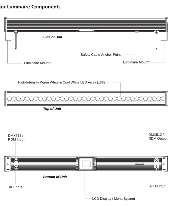
1. SL STRIP 400 TW LED Luminaire Components
Major Luminaire Components
Figure 1: SL STRIP 400 TW LED Luminaire Components
Note: *Mounts can be removed and reversed. See "Mounting Luminaire" on page 9 for more information Side of Unit
Bottom of Unit DMX512 /
AC Input
LCD Display / Menu System
Luminaire Mount* Safety Cable Anchor Point
RDM Input
Top of Unit
DMX512 /
AC Output RDM Output Luminaire Mount*
Connecting Power
7
SL STRIP 400 TW LED Luminaires
Installation & User’s ManualSh wline
Connecting SL STRIP 400 TW LED Luminaires to AC Power
If the unit is supplied with an AC input cable without an input connector installed. The input connector is a user-supplied accessory.
Table 2 describes how to connect power to your SL STRIP 400 TW LED Luminaire. Field wiring of the SL STRIP 400 TW LED Luminaire is straight forward. A total of 3 wires/conductors is supplied from the unit. The following wiring scheme is used:
Table 2: SL STRIP 400 TW LED Luminaire (IP65 Rated Models) AC Input Connections
Figure 3: SL STRIP 400 TW LED Luminaire AC Input & Output Connections
CAUTION: In the event the AC input cable of this luminaire is damaged, it must be replaced, by the user, with an approved cable through an Authorized Showline Dealer or Service Center.
Wire Color Purpose
Brown Main / Line (100 to 240VAC) Blue Neutral Green/Yellow Ground (Earth)
Bottom of Unit
Installation & User’s Manual
SL STRIP 400 TW LED Luminaires
8 INSTALLATION AND SET UP
Sh wline
3. Connecting to the DMX512 Network
Basic DMX512 installation consists of connecting multiple SL STRIP 400 TW LED Luminaires together (up to 32 luminaires) in "daisy-chain" fashion. A cable runs from the control console (or DMX512 control source) to the DMX connector on the first SL STRIP 400 TW LED Luminaire. Another cable runs from the other DMX connector on the first unit to a DMX connector on the next SL STRIP 400 TW LED Luminaire (or DMX512 device to be controlled).
Figure 4: SL STRIP 400 TW LED Luminaire DMX512 Input / Output Connections
Note: For more information on DMX512 networking and systems, refer to "Additional Resources for DMX512" on page 1. For SL STRIP 400 TW LED Luminaire DMX Mapping, refer to "DMX CONTROL" on page 17.
Figure 5: SL STRIP 400 TW LED Luminaire - DMX512 Connections
Bottom of Unit
DMX512 / RDM Input DMX512 / RDM Output
DMX512
DMX512 (out from first to second luminaire)
DMX512 (out to the next luminaire or DMX512
controlled device) SL STRIP 400 TW
DMX512 Connections
Note: Remaining pins on each connector are not used.
DMX512 Signal XLR Pin
Common (Drain) 1 DMX512 - 2 DMX512 + 3
(from console or control device)
Mounting Luminaire
9
SL STRIP 400 TW LED Luminaires
Installation & User’s ManualSh wline
4. Mounting Luminaire
The SL STRIP 400 TW LED Luminaire is provided with two mounts and a safety cable anchor point (as described in
"Major Luminaire Components" on page 4).
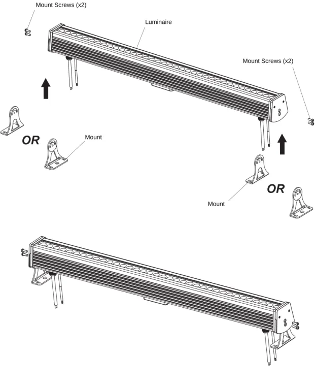
The two mounts are easily removed and reversed as required (as illustrated in Figure 6). These mounts are designed to accept a variety of mounting hooks, clamps, etc. for hanging applications or can be set on the mounts for floor applications. Refer to Figure 7 for additional information.
Figure 6: Mount Removal and Installation
OR
OR
Mount Screws (x2)
Mount
Mount
Mount Screws (x2) Luminaire
Installation & User’s Manual
SL STRIP 400 TW LED Luminaires
1 0 INSTALLATION AND SET UP
Sh wline
Simply attach hook, clamp, etc. to the SL STRIP 400 TW LED Luminaire mount assembly in the M10 hole.
Note: Mounting hooks, clamps, etc. are sold separately or by others. For available mounting accessories refer to "SL STRIP 400 TW LED Luminaire Accessories" on page 3.
Figure 7: Mounting Luminaire - Hanging Applications
Hooks / Clamps
(sold separately)
Mount
SAFETY CABLE: Is sold separately and recommended for all hanging installation and may be required by national and local codes. Use safety cable anchor point for this fixture.
Mounting hole size is M10.
Note:
Table 11, “SL STRIP 400 TW LED Luminaire RDM Parameter IDs,” on page 27