30RB/30RQ
PRO-DIALOG
Control
Operation and maintenance instructions
RA
A BB CC
A
A
B
B
C
Contents
1 - SAFETY CONSIDERATIONS ... 4
1.1 - General ... .4
1. - Avoid electrocution ... .4
2 - GENERAL DESCRIPTION ... 4
.1 - General ... .4
. - Abbreviations used... .4
3 - HARDWARE DESCRIPTION ... 5
3.1 - General ... .5
3. - Electrical supply to boards ... .5
3.3 - Light emitting diodes on boards ... .5
3.4 - The sensors ... .5
3.5 - The controls ... .6
3.6 - Connections at the user’s terminal block ... .6
4 - SETTING UP PRO-DIALOG PLUS CONTROL ... 9
4.1 - User interface general features ... .9
4. - Unit start/stop control ... .10
4.3 - Menus ... .11
5 - PRO-DIALOG PLUS CONTROL OPERATION ... 30
5.1 - Start/stop control ... .30
5. - Heating/cooling/standby operation ... .30
5.3 - Evaporator water pump control ... .31
5.4 - Control interlock contact ... .31
5.5 - Evaporator antifreeze protection ... .31
5.6 - Control point ... .3
5.7 - Demand limit ... .33
5.8 - Night mode ... .33
5.9 - Capacity control ... .33
5.10 - Head pressure control ... .33
5.11 - Defrost function ... .34
5.1 - Additional electric heater stage control ... .34
5.13 - Control of a boiler ... .34
5.14 - Master/slave assembly ... .34
5.15 - Optional heat reclaim module ... .35
5.16 - Free cooling option ... .35
6 - DIAGNOSTICS - TROUBLESHOOTING ... 36
6.1 - General ... .36
6. - Displaying alarms ... .36
6.3 - Resetting alarms ... .36
GENERAL LEGEND
Each of the following drawings is replaced in the whole document by the corresponding explanation:
Start/stop button
Return key
Down arrow
Up arrow
DELTA T. Example: temperature difference between entering and leaving heat exchanger temperatures
Means character is flashing
1 - SAFETY CONSIDERATIONS
1.1 - General
Installation, start-up and servicing of equipment can be
hazardous if certain factors particular to the installation are
not considered: operating pressures, presence of electrical
components and voltages and the installation site (elevated
plinths and built-up up structures). Only properly qualified
installation engineers and highly qualified installers and
technicians, fully trained for the product, are authorised to
install and start-up the equipment safely. During all servicing
operations all instructions and recommendations which appear
in the installation and service instructions for the product,
as well as on tags and labels fixed to the equipment and
components and accompanying parts supplied separately, must
be read, understood and followed.
•
Apply all standard safety codes and practices.
•
Wear safety glasses and gloves.
•
Use the proper tools to move heavy objects. Move units
carefully and set them down gently.
1.2 - Avoid electrocution
Only personnel qualified in accordance with IEC (International
Electrotechnical Commission) recommendations may be
permitted access to electrical components. It is particularly
recommended that all sources of electricity to the unit be shut
off before any work is begun. Shut off the main power supply
at the main circuit breaker or isolator.
IMPORTANT: This equipment uses and emits electromagnetic
signals. Tests have shown that the equipment conforms to all
applicable codes with respect to electromagnetic compatibility.
RISK OF ELECTROCUTION: Even when the main circuit
breaker or isolator is switched off, certain circuits may still
be energised, since they may be connected to a separate power
source.
RISK OF BURNS: Electrical currents cause components
to get hot either temporarily or permanently. Handle power
cable, electrical cables and conduits, terminal box covers and
motor frames with great care.
Fan start-up:
ATTENTION: In accordance with the operating conditions
the fans can be cleaned periodically. A fan can start at any
time, even if the unit has been shut down.
2 - GENERAL DESCRIPTION
2.1 - General
Pro-Dialog is a system for controlling single-, dual- or triple-
circuit 30RB air-cooled liquid chillers or 30RQ air-to-water
heat pumps. Pro-Dialog controls compressor start-up needed
to maintain the desired heat exchanger entering or leaving
water temperature. In cooling mode it controls the operation
of the fans to maintain the correct condensing pressure in
each circuit. For heat pump units it controls and optimises the
defrost cycles of each circuit in order to minimize the heating
capacity reduction. Safety devices are constantly monitored by
Pro-Dialog to ensure their safe operation. Pro-Dialog also gives
access to a Quick Test program covering all inputs and outputs.
All PRO-DIALOG Plus controls can work in accordance with
three independent modes:
•
Local mode: the machine is controlled by commands from
the user interface.
•
Remote mode: the machine is controlled by remote
contacts (volt-free contacts).
•
CCN mode: the machine is controlled by commands from
the Carrier Comfort Network (CCN). In this case, a data
communication cable is used to connect the unit to the
CCN communication bus.
The operating mode must be chosen with the Start/Stop button
described in section 4..1. When the PRO-DIALOG Plus
system operates autonomously (Local or Remote mode) it
retains all of its own control capabilities but does not offer any
of the features of the CCN network.
2.2 - Abbreviations used
In this manual, the refrigeration circuits are called circuit
A, circuit B and circuit C. The compressors in circuit A are
labelled A1, A, A3 and A4. Those in circuit B are B1, B, B3
and B4 and those in circuit C are C1, C, C3 and C4.
The following abbreviations are used frequently:
CCN : Carrier Comfort Network
CCn : Operating type: CCN
LED : Light Emitting Diode
LEN : Sensor Bus (internal communication bus linking the
basic board to the slave boards)
LOFF : Operating type: Local Off
L-On : Operating type: Local On mode
L-Sc : Operating type: Local On following a time schedule
MASt : Operating type: master unit (master/slave assembly)
rEM : Operating type: by remote contacts
SCT : Saturated Condensing Temperature
SST : Saturated Suction Temperature
EXV : Electronic Expansion Valve
3
2
14
6
7
5
1
3 - HARDWARE DESCRIPTION
3.1 - General
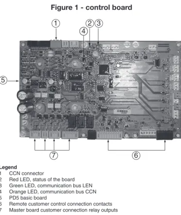
Figure 1 - control board
3.2 - Electrical supply to boards
All boards are supplied from a common 4 V a.c. supply
referred to earth.
CAUTION: Maintain the correct polarity when connecting
the power supply to the boards, otherwise the boards may be
damaged.
In the event of a power supply interrupt, the unit restarts
automatically without the need for an external command.
However, any faults active when the supply is interrupted are
saved and may in certain cases prevent a circuit or unit from
restarting.
3.3 - Light emitting diodes on boards
All boards continuously check and indicate the proper
operation of their electronic circuits. A light emitting diode
(LED) lights on each board when it is operating properly.
•
The red LED flashing for a second period on the
NRCP-BASE board indicates correct operation. A different rate
indicates a board or a software failure.
•
The green LED flashes continuously on all boards to show
that the board is communicating correctly over its internal
bus. If the LED is not flashing, this indicates a LEN bus
wiring problem.
•
The orange LED of the master board flashes during any
communication via the CCN bus.
3.4 - The sensors
Pressure sensors
Two types of electronic sensors are used to measure the suction
and discharge pressure in each circuit.
Thermistors
The evaporator water sensors are installed in the entering and
leaving side. The outdoor temperature sensor is mounted below
the control box. An optional water system temperature sensor
can be used for master/slave assembly control (in the case of
leaving water control).
In heat pump units a sensor placed on an air heat exchanger
pipe ensures defrost operation.
Legend
1 CCN connector
2 Red LED, status of the board
3 Green LED, communication bus LEN
4 Orange LED, communication bus CCN
5 PD5 basic board
6 Remote customer control connection contacts
7 Master board customer connection relay outputs
The control system consists of a PD5-BASE board, SPM
boards for compressor control, PD-AUX boards for fan
control, and an NRCP-BASE board for units equipped with
energy management option or heat reclaim option. All boards
communicate via an internal LEN bus. The PD5-BASE boards
continuously manage the information received from the various
pressure and temperature probes, and incorporates the program
that controls the unit.
The user interface consists of two display blocks with up to 6
LEDs and 16 buttons (according to unit type). It is connected to
the main basic board and gives access to a full array of control
parameters.
3.6 - Connections at the user’s terminal block
3.6.1 - General description
The contacts below are available at the user’s terminal block
on the PD5-BASE board (see figure 1). Some of them can only
be used if the unit operates in remote operating type (rEM).
The following table summarises the connections at the user’s
terminal block.
3.5 - The controls
Evaporator pumps
The controller can regulate one or two evaporator pumps and
takes care of automatic change-over between pumps.
Evaporator heater
It protects the evaporator (and the pipe heater for units without
pump) against freezing if the unit is off.
Boiler
This relay output authorises start/stop of a boiler.
COOLING UNITS
Description Connector/
channel Terminal Board Remarks
Evaporator pump 1 control J2A / CH19 PD5-BASE The control can regulate one or two evaporator pumps, and automatically change over between the two pumps.
Evaporator pump 2 control J2A / CH20 PD5-BASE The control can regulate one or two evaporator pumps, and automatically change over between the two pumps.
Evaporator heater control J2B / CH21 PD5-BASE This (and the pipe heater for units without pumps) protects the evaporator against frost. Alarm relay output J3 / CH24 PD5-BASE Indicates alarms
Alert relay output J3 / CH25 PD5-BASE Indicates alerts Operation or ready-to-start
relay output J3 / CH26 PD5-BASE Indicates if the unit is ready to start or operates. Contact 1:
Start/stop
J4 / CH11 32-33 PD5-BASE This contact is used for unit start/stop. It is only taken into account if the unit is under remote operation control (rEM).
Contact 2: Setpoint selection
J4 / CH12 65-66 PD5-BASE This contact is only taken into account if the unit is under remote operation control (rEM).
Contact 3:
Demand limit selection 1 J4 / CH13 63-64 PD5-BASE See the description of these contacts in sections 3.6.5 and 3.6.6. Contact 3 bis:
Demand limit selection 2
CH9 NRCP2-BASE This contact is only present if the energy management option is used.
User safety loop input J4 / CH15a 34-35 PD5-BASE This contact is mounted in series with the water flow control contact. It can be used for any customer safety loop that requires that the unit is stopped, if it is open. If it is unused this contact must be bridged.
Contact 4:
Heat reclaim selection
J4 / CH14 PD5-BASE This contact is used to select the heat reclaim mode.This contact is only used, if the heat reclaim option is used (not compatible with the free cooling option).
Contact 4:
Free cooling prevention J4 / CH14 PD5-BASE If this contact is closed, it is used to prevent operation of the free cooling mode. It is only taken into account, if the unit is under remote operation control (rEM). This contact is only used if the free cooling option is used (incompatible with the heat reclaim option). Contact 5:
Pump operation status J5C / CH18 PD5-BASE If this contact is open, the pump is controlled and an alarm has tripped. Connection to CCN J12 PD5-BASE An RS-485 bus is used for connection to the CCN.
- Pin 1: signal + - Pin 2: ground Pin 3: signal
-Critical alarm relay output J2C / CH23 PD5-BASE Output allows disconnecting the general unit power supply, if a contactor is stuck and there is an increased risk of the unit being damaged.
HEAT PUMP UNITS
Description Connector/
channel Terminal Board Remarks
Evaporator pump 1 control J2A / CH19 PD5-BASE The control can regulate one or two evaporator pumps, and automatically change over between the two pumps.
Evaporator pump 2 control J2A / CH20 PD5-BASE The control can regulate one or two evaporator pumps, and automatically change over between the two pumps.
Evaporator heater control J2B / CH21 PD5-BASE This (and the pipe heater for units without pumps) protects the evaporator against frost.
4-way valve A control J2C/ CH22 PD5-BASE The control regulates the 4-way valve during heat/cool changeover or during defrost cycles.
4-way valve B control J2C/ CH23 PD5-BASE The control regulates the 4-way valve during heat/cool changeover or during defrost cycles.
Alarm relay output J3 / CH24 PD5-BASE Indicates alarms Alert relay output J3 / CH25 PD5-BASE Indicates alerts Operation or ready-to-start
relay output J3 / CH26 PD5-BASE Indicates if the unit is ready to start or operates. Contact 1:
Start/stop
J4 / CH11 32-33 PD5-BASE This contact is used for unit start/stop. It is only taken into account if the unit is under remote operation control (rEM).
Contact 2:
Setpoint selection J4 / CH12 65-66 PD5-BASE This contact is only taken into account if the unit is under remote operation control (rEM). Contact 3:
Demand limit selection 1
J4 / CH13 63-64 PD5-BASE See the description of these contacts in sections 3.6.5 and 3.6.6. Contact 3 bis:
Demand limit selection 2
CH9 NRCP2-BASE This contact is only present if the energy management option is used.
User safety loop input J4 / CH15a 34-35 PD5-BASE This contact is mounted in series with the water flow control contact. It can be used for any customer safety loop that requires that the unit is stopped, if it is open. If it is unused this contact must be bridged.
Contact 4:
Heating/cooling selection J5B / CH17 PD5-BASE This contact is used for heating/cooling mode selection. It is only taken into account if the unit is under remote operation control (rEM). Contact 5:
Pump operation status
J5C / CH18 PD5-BASE If this contact is open, the pump is controlled and an alarm has tripped. Connection to CCN J12 PD5-BASE An RS-485 bus is used for connection to the CCN.
- Pin 1: signal + - Pin 2: ground Pin 3: signal
-Critical alarm relay output J2C / CH22 NRCP2-BASE Output allows disconnecting the general unit power supply, if a contactor is stuck and there is an increased risk of the unit being damaged (available if the energy management option is used).
3.6.2 - Volt-free contact on/off/cooling/heating without
multiplexing
If the automatic heating/cooling changeover function is not
selected (see section 5.) and if the user configuration allows
this (heat pump and Pro-Dialog interface selection) the operation
of contacts 1 and 4 is as follows:
OFF ON cooling ON heating Contact 1 Open Closed Closed
Contact 4 - Open Closed
Contact status not significant
3.6.3 - Volt-free contact on/off/cooling/heating with
multiplexing
If the automatic heating/cooling changeover function is selected
(see section 5.) and if the user configuration allows this (heat
pump and Pro-Dialog interface selection) the operation of
contacts 1 and 4 is multiplexed:
OFF ON cooling ON heating ON auto Contact 1 Open Closed Closed Open
Contact 4 Open Open Closed Closed
NOTE: The automatic changeover function (ON auto) selects
the cooling or heating mode based on the outdoor temperature
(see section 5.2).
3.6.4 - Volt-free setpoint selection
This volt-free contact permits changing the setpoint. The
setpoints can be modified in the setpoint menu.
Cooling Heating
CSP 1 CSP2 Auto HSP1 HSP2 Auto Contact 2 Open Closed - Open Closed
-3.6.5 - Volt-free demand limit contact with energy
management option
For units with the energy management option the demand limit
contact 3 is located on the PD5-BASE board and contact 3 bis is
on the NRP-BASE board. Demand limit is now multiplexed.
Capacity
100% limit 1 limit 2 limit 3 Contact 3 Open Closed Open Closed
Contact 3 bis Open Open Closed Closed
3.6.6 - Volt-free demand limit contact without energy
management option
For units without energy management option, contact 3 is
located on the PD5-BASE board.
Capacity
100% limit 1 Contact 3 Open Closed
MAIN INTERFACE
BUTTON NAME DESCRIPTION
Menu Permits the selection of a main menu. Each main menu is represented by an icon. The icon is lit if active.
Up arrow Permits scrolling through the menu items (in the two-digit display). If the modification mode is active this button authorises increase of the value of any parameter.
Down arrow Permits scrolling through the menu items (in the two-digit display). If the modification mode is active this button authorises decrease of the value of any parameter.
Enter Gives access to the modification mode, validates a modification or displays expanded item description. Start/stop Authorises start or stop of the chiller in local mode or modification of its operating type.
MAIN INTERFACE MENU LEDS
LED NAME DESCRIPTION
INFORMATION menu Displays the general operating parameters for the unit. TEMPERATURES menu Displays the unit operating temperatures.
PRESSURES menu Displays the unit operating pressures.
SETPOINTS menu Displays the unit setpoints and enables them to be modified. INPUTS menu Displays the status of the unit digital and analogue inputs.
OUTPUTS/TESTS menu Displays the status of the unit outputs and enables them to be tested. CONFIGURATIONS menu Displays the unit configuration and enables it to be modified. ALARMS menu Displays active alarms.
ALARMS HISTORY menu Displays the history of the alarms.
OPERATING LOG menu Displays the operating times and number of starts for the unit and the compressors.
The local interface enables a number of operating parameters
to be displayed and modified. The interface consists of two
distinct parts: the main interface (left hand section) and the
summary interface (right hand section).
Main interface
It gives access to all PRO-DIALOG PLUS data and operating
functions. It consists of:
•
A two-digit display showing the number of the item
selected.
•
A four-digit display showing the contents of the item
selected.
•
LEDs and buttons for unit start/stop, menu selection,
menu item selection and value adjustment.
MAIN INTERFACE
SUMMARy INTERFACE
MENU BLOCk
4 - SETTING UP PRO-DIALOG PLUS CONTROL
4.1 - User interface general features
DUAL-CIRCUIT HEAT PUMP INTERFACE
DUAL-CIRCUIT CHILLER INTERFACE
MAIN INTERFACE
SUMMARy INTERFACE
MENU BLOCk
MAIN INTERFACE
SUMMARy INTERFACE
MENU BLOCk
TRIPLE-CIRCUIT CHILLER INTERFACE
R
A
A BB
A
A BB
A A
A A
B B
B B
R A
A BB CC
A
A
B
B
C
4.2 - Unit start/stop control
4.2.1 - Description
The unit start/stop can be controlled by one of the following
methods:
•
Locally on the actual unit (Local control type)
•
By remote control with the aid of user contacts (remote
control type)
•
By CCN control with the aid of the CCN (CCN control
type)
The main interface includes a Start/Stop button which can be
used to stop or start the unit in the local operating type or to
select the remote or CCN operating type.
The available operating types are described in the following
table.
The following operating types can be selected using the
Start/Stop button:
OPERATING TyPES 4-DIGIT
DISPLAy DESCRIPTION
LOFF Local Off. The unit is halted in local mode.
L-On Local On. The unit is in local control mode and is authorised to start.
L-Sc* Local On - timer control. The unit is in local control mode. It is authorised to start if the period is occupied. If the timer program for unit operation is unoccupied, the unit remains shut down until the period becomes occupied.
CCN CCN. The unit is controlled by CCN commands. rEM Remote. The unit is controlled by remote control contacts. MAST* Master Unit. The unit runs as a master in a two unit lead/lag
arrangement. This is displayed if the unit is configured for master/ slave control.
* Displayed if the configuration requires it.
Section 5.1 gives a more detailed description of the commands to start/stop the unit, analysed by operating type.
4.2.2 - Stopping the unit in local mode
The unit can be stopped in local mode at any time by pressing
the Start/Stop button.
TO STOP THE UNIT
BUTTON ACTION 2-DIGIT
DISPLAy 4-DIGIT DISPLAy
Press the Start/Stop button for less than 4 seconds (one short press is enough).
C LOFF
If the button is released, the unit stops without the need for further action.
t LOFF
4.2.3 - Starting unit and selecting an operating type
The unit can be started in local mode, or unit operating type
can be changed at any time using the Start/Stop button. In the
example that follows, the unit is stopped (LOFF) and the user
wants to start the unit in local mode.
The summary interface (right hand section) includes a mimic
diagram of the unit, together with push-buttons and LEDs. It
gives quick access to the main operating parameters of the unit.
SUMMARy INTERFACE LEDS LED INDICATION WHEN LIT
Green LED:
The unit is authorised to start or is already running
Red LED:
- Lit: circuit A or unit shut down by alarm
- Flashing: circuit A or unit running with alarm present
Red LED:
- Lit: circuit B or unit shut down by alarm
- Flashing: circuit B or unit running with alarm present
Red LED:
- Lit: circuit C or unit shut down by alarm
- Flashing: circuit C or unit running with alarm present
Green LED:
The evaporator pump is running.
yellow LEDs:
From top to bottom - start/stop status of compressor A1, A2, A3 and A4 or B1, B2, B3 and B4 or C1, C2, C3 and C4. Flashing LED indicates that the circuit is in the protection or defrost mode (A, B or C).
Green LED:
The unit operates in heating mode.
Green LED:
The unit operates in cooling mode.
SUMMARy INTERFACE PUSH BUTTONS (DUAL-CIRCUIT) BUTTON DISPLAy
Blue button: evaporator leaving or entering water temperature in °C Gray button: outdoor air temperature in °C
Control point (setpoint + reset) in °C Press 1: circuit A/B discharge pressure in kPa
Press 2: circuit A/B saturated condensing temperature in °C Press 1: circuit A/B suction pressure in kPa
Press 2: circuit A/B saturated suction temperature in °C Press 1: compressor A1/B1 operating hours in h/10 or h/100 Press 2: compressor A2/B2 operating hours in h/10 or h/100 Press 3: compressor A3/B3 operating hours in h/10 or h/100 Press 4: compressor A4/B4 operating hours in h/10 or h/100
(1) There is a separate button for each of the two circuits.
SUMMARy INTERFACE PUSH BUTTONS (TRIPLE-CIRCUIT) BUTTON DISPLAy
Blue button: evaporator leaving or entering water temperature in °C Gray button: outdoor air temperature in °C
Control point (setpoint + reset) in °C
Press 1: circuit A/B/C discharge pressure in kPa
Press 2: circuit A/B/C saturated condensing temperature in °C Press 1: circuit A/B/C suction pressure in kPa
Press 2: circuit A/B/C saturated suction temperature in °C Press 1: compressor A1/B1/C1 operating hours in h/10 or h/100 Press 2: compressor A2/B2/C2 operating hours in h/10 or h/100 Press 3: compressor A3/B3/C3 operating hours in h/10 or h/100 Press 4: compressor A4/B4/C4 operating hours in h/10 or h/100 Press 1: Selects circuit A to display information
(only on triple-circuit units)
Press 1: Selects circuit B to display information (only on triple-circuit units)
Press 1: Selects circuit C to display information (only on triple-circuit units)
(1) There is a common button for the three circuits; for circuit selection press one of the three last buttons described above.
(1) (1) (1)
A
A
A
A
A
AB
A
AC
(1) (1) (1)
A
B
C
START UP WITH THE PREVIOUSLy USED OPERATING TyPE WHEN THE UNIT IS STOPPED IN LOCAL MODE (LOFF)
BUTTON ACTION 2-DIGIT
DISPLAy 4-DIGIT DISPLAy
The unit is in local stop mode. The previously used operating type is local on (L-ON)
LOFF Press the Start/Stop button for 4 seconds
(one short press-down is sufficient). L-ON illuminates immediately. “C” flashes in the 2-digit display to show that the controller is awaiting confirmation.
L-On
Press the Enter button to confirm the operating type. “t” is displayed in the 2-digit display to indicate the operating type selected. If the Enter button is not pressed soon enough, the controller will cancel the change and remain in the stop mode.
L-On
CHANGING THE OPERATING TyPE
BUTTON ACTION 2-DIGIT
DISPLAy 4-DIGIT DISPLAy
Continually press the operating type selection button for more than 4 seconds.
C LOFF
Hold down the Start/Stop button. The available operating types are displayed one by one until the button is released.
L-On L-Sc
rEM Release the Start/Stop button if the
operating type you want is displayed (in this example L-On). “C” flashes in the 2-digit display to show that the controller is awaiting confirmation.
Press the Enter button to confirm the operating type selected (in this example: L-On). “t” is displayed in the 2-digit display to indicate the operating type selected. If the Enter button is not pressed soon enough, the controller will cancel the change and continue to use the previous operating type.
t L-On
4.3 - Menus
4.3.1 - Selecting a menu
The MENU button authorises you to select a menu from the 10
main menus that are available. Each time you press this button
one of the 10 LEDs lights up in turn alongside each of the icons
representing a main menu. The active menu is the one against
which the LED is lit. If a menu is empty then its LED is not lit.
To scroll quickly through the menus, hold the MENU button
down.
4.3.2 - Selecting a menu item
The up and down Arrow buttons let you scroll through the
menu items. Menu item numbers are displayed in the two-digit
display. The item number increases or decreases every time
you press the up or down Arrow button. The menu items that
are not in use or incompatible with the configuration are not
displayed. The value or status associated with the active item
is displayed in the four-digit display. To scroll quickly through
the items, hold the up or down Arrow button down.
The following example shows how to access item 3 in the
Pressures menu.
SELECTING A MENU ITEM
OPERATION PRESS
BUTTON MENU LED ITEM NUMBER 2-DIGIT DISPLAy
Press the MENU button until the LED marked PRESSURE lights.
0 0 Press one of the Arrow buttons
until the two-digit display shows 3 (item number 3).
1 2 3
4.3.3 - Modifying the value of a parameter/access to a
sub-menu
Press the Enter button for more than seconds to enter the
modification mode or to select a sub-menu. This lets you correct
the value of an item or select a sub-menu with the aid of the
up and down Arrow buttons (if you are authorised to overwrite
the item concerned). When modification mode is activated, the
LED for the main menu to which the item belongs as well as
the -digit display flash in the menu block. Once the required
value is obtained, press the Enter button again to validate the
change or to access the sub-menu. The LED for the menu
to which the item and the -digit display belong then stops
flashing, indicating that modification mode no longer applies.
In modification mode, the value to be modified increases or
decreases in steps of 0.1 every time you press the Arrow buttons.
Holding one of these buttons down increases the rate of
increase or decrease.
NOTE: The access to a sub-menu may require entering a
password. This is automatically requested. See section 4.3.11.2.
The following example shows how to modify the value of item
1 in the Setpoint menu.
MODIFyING THE VALUE OF A PARAMETER
OPERATION VALUE PRESS
BUTTON MENU LED ITEM NUMBER 2-DIGIT DISPLAy ITEM 4-DIGIT DISPLAy
Hold on the MENU button until the LED for SETPOINT lights. 0
0 Press one of the Arrow buttons until the two-digit display shows 1 (item number 1- cooling
setpoint 2). The value for setpoint 2 is displayed in the four-digit display (6.0°C in this example).
1 1
6.0
Press the Enter button for more than 2 seconds to enable the value associated with item 1 to be modified. The Setpoint menu LED and the two-digit display flash indicating that modification mode is active.
6.0
Keep pressing the Down Arrow button until the value 5.7 is displayed in the four-digit display. The Setpoint menu LED and the two-digit display keep flashing.
5.9
5.8
5.7 Press the Enter button again to validate the change. The new setpoint is 5.7°C.The Setpoint menu
LED and the two-digit display stop flashing, indicating that modification mode no longer applies.
1 5.7
4.3.4 - Expand display
Pressing the Enter button causes a 3 character text expansion
to be scrolled across the four-digit display. All user menus
provide an expansion of the current displayed parameters.
If the expansion is complete the four-digit display reverts to
item value. This function can be inhibited through the User
Configuration menu.
1
1
1
1
RUNTIME
USER [USEr]
SER VICE [SErviCE] FACTOR y [F ACtor y ]
RUNTIME 1 [RuntiME 1] RUNTIME 2 [RuntiME 2] MAINTENANCE [MAintEnAnCE]
PERIOD
3
[PEriod 3] PERIOD
4
[PEriod 4] PERIOD
5
[PEriod 5] PERIOD
6
[PEriod 6] PERIOD
7
[PEriod 7] PERIOD
8
[PEriod 8]
PERIOD
1
[PEriod 1] PERIOD
2
[PEriod 2]
USER 2 [USEr 2] SCHEDULE 1 [SCHEduLE 1] SCHEDULE 2 [SCHEduLE 2]
HOLIDA
YS
[HoLidA
y]
HOUR + DA
TE [dAtE] BROADCAST [br odCASt] SER VICE 1 [SErviCE 1] SER VICE 2 [SErviCE 2] MASTER/SLA VE [MAStEr SLA vE] HSM [HSM] PERIOD 3
[PEriod 3] PERIOD
4
[PEriod 4] PERIOD
5
[PEriod 5] PERIOD
6
[PEriod 6] PERIOD
7
[PEriod 7] PERIOD
8
[PEriod 8]
PERIOD
1
[PEriod 1] PERIOD
2 [PEriod 2] HOLIDA YS 3 [HoLidA y 3] HOLIDA YS 4 [HoLidA y 4] HOLIDA YS 5 [HoLidA y 5] HOLIDA YS 6 [HoLidA y 7] HOLIDA YS 7 [HoLidA y 7] HOLIDA YS 8 [HoLidA y 8] - - - - - - -HOLIDA YS 16 [HoLidA y16] HOLIDA YS 1 [HoLidA y 1] HOLIDA YS 2 [HoLidA y 2]
MAIN MENUS
SUB-MENUS
SUB-SUB-MENUS
SUB-SUB-SUB-MENUS
Menu structure
NO
TE: The items in brac
kets sho
w
what is displayed on the user interface.
OUTPUT 2
RUNTIME 3 [RuntiME 3]
USER 1 [USEr 1]
OUTPUT 1 TEMPERA TURES ST A TUS PRESSURES SETPOINTS INPUTS OUTPUTS CONFIGURA TION ALARMS ALARMS HISTOR y
Menu tree structure
TEMP PRESSURES SETPOINTS INPUTS OUTPUTS CONFIG ALARMS ALARMS HISTOR y RUNTIMESEvaporator water entering temp.
Dischar ge pr essur e cir cuit A
Cooling setpoint 1
Contact 1: on/of
f/heating/
cooling
Output 1
SUB-MENU: User Configuration (USEr) Number of active alarms/r
esets**
Historic alarm code 1**
SUB-MENU: Runtimes 1
Evaporator water leaving temp.
Suction pr
essur
e
cir
cuit A
Cooling setpoint 2
Contact 2: setpoint selection
Output 2
SUB-MENU: Service Configuration (SErviCE)
Active alarm code 1**
Historic alarm code 2**
SUB-MENU: Runtimes 2
Outdoor temperatur e Dischar ge pr essur e cir cuit B*
Ice storage setpoint*
Contact 4: heating/cooling [1]*
-SUB-MENU: Factory Configuration (FACtorY)
Active alarm code 2**
Historic alarm code 3**
SUB-MENU: Runtimes 3
Heat r eclaim entering water temp.* Suction pr essur e cir cuit B*
Heating setpoint 1*
Contact 4: heat r
eclaim
[2]* OR fr
ee cooling
pr
evention [2]
-Active alarm code 3**
Historic alarm code 4**
SUB-MENU: Maintenance
Heat r eclaim leaving water temp.* Dischar ge pr essur e cir cuit C*
Heating setpoint 2*
User safety loop input status
-Active alarm code 4**
Historic alarm code 5**
-Saturated dischar ge temperatur e cir cuit A Suction pr essur e cir cuit C*
Auto changeover thr
eshold
(cooling mode)*
W
ater pump operation
contact status*
-Active alarm code 5**
Historic alarm code 6**
-eclaim
Saturated suction temp. cir
cuit A Vacuum pr essur e, cir cuit A*
Auto changeover thr
eshold
(heating mode)*
Contr
ol box thermostat
-Historic alarm code 7**
-Suction temperatur e, cir cuit A Vacuum pr essur e, cir cuit B* Heat r
eclaim mode input
setpoint*
Contact 3: demand limit selection 1*
-Historic alarm code 8**
-cuit Superheat, cir cuit A -Heat r
eclaim mode input
dead band*
Contact 3 bis: demand limit selection 2*
-Historic alarm code 9**
-cuit Saturated dischar ge temp. cir cuit B
-Setpoint demand limitation 1*
Ice storage r
emote
contact*
-Historic alarm code 10**
-cuit C Saturated dischar ge temp. cir cuit B
-Setpoint demand limitation 2*
Remote unit contact, continued
occupied
mode*
-Historic alarm code 11**
-Suction temperatur e, cir cuit B
-Setpoint demand limitation 3*
User safety loop input*
-Historic alarm code 12**
-Superheat, cir
cuit B
-Ramp loading*
Demand limit contr
ol
limitation value*
-Historic alarm code 13**
-ol Saturated dischar ge temp. cir cuit C*
-Cooling - zer
o r eset thr eshold* Setpoint r eset value*
-Historic alarm code 14**
-Saturated dischar ge temp. cir cuit C*
-Cooling - full r
eset thr eshold* Ambient temperatur e value*
-Historic alarm code 15**
-Suction temperatur e, cir cuit C*
-Cooling - full r
eset value*
Subcooling liquid temperatur
e, cir
cuit A*
-Historic alarm code 16**
-ol point
Superheat, cir
cuit C*
-Heating - zer
o r
eset
thr
eshold*
Subcooling liquid temperatur
e, cir
cuit B*
-Historic alarm code 17**
-olled water e Defr ost temperatur e, cir cuit A*
-Heating - full r
eset thr eshold* Subcooling temperatur e, cir cuit A*
-Historic alarm code 18**
-, heat ess, cir cuit A* Defr ost temperatur e, cir cuit B*
-Heating - full r
eset value* Subcooling temperatur e, cir cuit B*
-Historic alarm code 19**
-, heat
ess, cir
cuit B*
System water temperatur
e*
-Historic alarm code 20**
if the configuration requires it 1 For heat pump units if the alarm exists 2 For cooling only units
INFORMATION MENU (3) ITEM FORMAT UNITS
0
±nn.n °C LOFF -L-On -L-Sc -CCn -rEM -MASt - OFF -rEADY -dELAY -StOPPing -running -triPout -OvErridE -dEFrOSt -FrEEcOOl -OCCUPIEd UNOCCUPIEd -COOL -HEAT -StAndbY -BotH -ALArM -ALErt -MAStEr -SLAvE -1 [-1] nn
-2 [-2]
-occu unoc Forc
3 nn.n minutes
4 [2]
-HEAt -COOL -Auto -5 [2]
HEAt -COOL -StbY -both -Forc -6 [2] Yes
-No Forc
6 [2] Yes -No
Forc
7 nnn %
8 nnn %
9 [2] nnn % 10 [2] nnn % 11 nnn
Forc % 12 [2] nnn % 13 [2]
-SP-1 SP-2 AUtO
4.3.5 - Description of the Information menu
DESCRIPTION
Automatic display mode. It cycles through the following displays:
1: Controlled water temperature: temperature of the water that the unit tries to maintain at the control point.
2: Unit operating type
Local Off Local On
Local On - based on unit clock. Displayed if the CCN/clock board is installed. CCN Control. Displayed if the CCN/clock board is installed.
Remote Control Master unit
3: Unit status
Off: Unit is stopped and not authorised to start. Ready: Unit is authorised to start
Delay: Unit is in delay at start-up. This delay is active after the unit has been switched on. The delay can be configured in the User Configuration menu.
Stopping: Unit is currently stopping. On: Unit is running or authorised to start. Fault shutdown.
Limit: The operating conditions do not allow total unit operation. Defrost: One circuit is in defrost mode.
Free cooling: The unit operates in free cooling mode.
4. Unit occupied/unoccupied status
Occupied: Unit in occupied mode Unoccupied: Unit in unoccupied mode
5. Heating/cooling operating mode
Cooling: Unit operates in cooling mode Heating: Unit operates in heating mode
Standby: Unit is in auto cooling/heating changeover mode, and is in standby
Both: The unit operates in cooling (compressors) and heating (boiler). Only with HSM operation.
6: Alarm mode
Alarm: Unit is totally stopped because of failure. Alert: Unit is in failure but not completely stopped.
7: Master/Slave status
Master: The master/slave control is active and the unit is the master Slave: The master/slave control is active and the unit is the slave
Texts 4 and 5 are not displayed if the unit is in Local off mode or if the unit is in remote control mode and contact 1 is open.
Active mode codes. Each active mode is displayed in turn. This Item is masked when nil. Pressing the enter button when a mode code is displayed causes a character text expansion to be scrolled accross the four-digit display. See the description in the follow-ing table
This item indicates the current unit occupied/unoccupied mode. Occupied
Unoccupied
The value is displayed in turn with ‘Forc’ when the unit is in CCN control and if this variable if forced through CCN.
Start-up delay. This item indicates the minutes left before the unit can be started. This delay at start-up is always active after the unit has been switched on. The delay can be configured in the User Configuration 1 menu.
Heating/cooling on selection: This item is accessible in read/write, if the unit is in local control mode. Heating mode selection
Cooling mode selection
Automatic heating/cooling mode changeover selection. Only displayed if the auto changeover function is selected (User Configura-tion 1 menu).
Heating/cooling mode. This item indicates whether the unit is in cooling or heating. Displayed if the unit controls a boiler. Heating
Cooling
Standby: Unit is in auto cooling/heating changeover mode, and is in standby.
Both: The unit operates in cooling (compressors) and heating (boiler). Only with HSM operation.
The value is displayed in turn with ‘Forc’ when the unit is in CCN control and if this variable if forced through CCN.
Heat reclaim mode selection. Only displayed if the unit is a chiller and the heat reclaim option is used. The value is displayed in turn with ‘Forc’ when the unit is in CCN control and if this variable if forced through CCN.
Free cooling prevention status. Only shown if the unit is a chiller and if the free cooling option is available. The value is displayed in turn with “Forc”, when the unit is in CCN control and if this variable is forced through CCN.
Total active capacity of unit. It is the percentage of compressor capacity used by the unit.
Total active capacity of circuit A. It is the percentage of compressor capacity used by on circuit A..
Total active capacity of circuit B. It is the percentage of compressor capacity used by on circuit B. Dual-circuit units only.
Total active capacity of circuit C. It is the percentage of compressor capacity used by on circuit C. Triple-circuit units only.
Present demand limit. This is the authorised operating capacity of the unit. See section 5.7.
The value is displayed in turn with ‘Forc’ when the unit is in CCN control and if this variable if forced through CCN.
Present lag chiller demand limit. Displayed when the master/slave control is selected.
Setpoint select in local mode. This point is read/write accessible. Displayed only when the unit is LOFF, L-On or L-Sc operating type.
SP-1 = cooling/heating setpoint 1 SP-2 = cooling/heating setpoint 2
DESCRIPTION
The delay at start-up operates after the unit has been switched on. If the delay has not expired, the mode is ac-tive. The delay is configured in the User Configuration 1 menu.
The second cooling/heating setpoint is active. See section 5.6.1
In this mode, the unit uses the reset function to adjust the leaving water temperature setpoint. In this mode, the demand at which the unit is authorised to operate is limited.
Ramp loading is active. This item is referenced to the allowed low and high temperature limits, controlled at the water heat exchanger in order to prevent compressor overloading. Ramp function must be configured (see User Configuration 1 menu). Ramp values can be modified (see Setpoint menu).
The water heat exchanger heater is active.
The unit is fitted with two evaporator water pumps and reversal between pumps is in effect.
The unit is stopped and the pump is started each day at 14.00 p.m. for two seconds. This function needs to be configured in the User Configuration 2 menu.
The night mode (low noise level) is active. The number of fans is reduced (if operating conditions allow) and unit capacity can be limited.
Unit is in control of a System Manager (FSM, CSM III or HSM).
Unit is connected to a secondary unit by a master slave link and the master/slave modes are active. If the unit is in auto mode, the heating/cooling changeover is automatic, based on the outdoor temperature. The free cooling mode is active.
The heat reclaim mode is active. The electric heating stages are active.
The unit is in heating mode and compressor start is not authorised, as the entering water temperature is below 10°C.
The unit controls a boiler and this is operating.
The unit operates in cooling mode and the ice storage mode is active.
19 = circuit A, 20 = circuit B. The unit is in heating mode, and the defrost sequence is active on the relevant circuit.
21= circuit A, 22 = circuit B, 23 = circuit C. Protection for evaporator low suction temperature circuit is active. In this mode, circuit capacity is not authorised to rise and the circuit can be unloaded.
24= circuit A, 25 = circuit B, 26 = circuit C. Hot gas discharge protection is active. In this mode, the circuit capacity cannot increase, and the circuit may be unloaded.
27 = circuit A, 28 = circuit B, 29 = circuit C. The circuit is in high pressure protection mode because the HP protection threshold has been exceeded. Circuit has been unloaded and the circuit capacity is not authorised to rise.
0 = circuit A, 31 = circuit B, 32 = circuit C. The circuit is in the low superheat protection mode to prevent the compressors drawing in liquid refrigerant.
MODE # MODE NAME
1 Delay at start-up active
2 2nd cooling/heating setpoint active 3 Setpoint reset active
4 Demand limit active 5 Ramp loading active
6 Water heat exchanger heater active
7 Evaporator pump reversal in effect 8 Evaporator pump periodic start 9 Night mode (low noise level) 10 Unit in SM control 11 Master/slave link active 12 Auto heating/cooling changeover
active
13 Free cooling mode active 14 Heat reclaim mode active 15 Electric heating stages active 16 Low water entering temperature
protection in heating mode 17 Boiler active
18 Ice storage mode active 19,20 Defrost
21,22,23 Low suction temperature protection 24,25,26 Hot gas protection
27,28,29 High pressure protection
30, 31, 32 Low superheat protection
INFORMATION MENU (3) continued ITEM FORMAT UNITS
14 [2] -occu unoc Forc 15 ±nn.n °C 16 ±nn.n
Forc °C
17 ±nn.n °C 18 n
19 n
[1] This item is masked when nil.
[2] This item is displayed in certain unit configurations only.
DESCRIPTION OF OPERATING MODES (ITEM 1 OF THE INFORMATION MENU) DESCRIPTION
Setpoint occupied mode.
Occupied: cooling setpoint 1 is active Unoccupied: cooling setpoint 2 is active
The value shall be displayed in turn with ‘Forc’ when the unit is in CCN control and if this variable if forced through CCN.
Active setpoint. This is the current cooling/heating setpoint: cooling/heating setpoints 1, 2 or ice storage setpoint.
Control point. This is the setpoint used by the controller to adjust the temperature of the leaving or entering water (according to configuration).
Control point = active setpoint + reset. See section 5.6
The value is displayed in turn with ‘Forc’ when the unit is in CCN control and if this variable if forced through CCN.
Controlled water temperature. Water temperature that the unit tries to maintain at the control point. Heat reclaim sequence indicator, circuit A (option).
4.3.6 - Description of the Temperatures menu
TEMPERATURES MENU [1]
ITEM FORMAT UNITS COMMENTS
0 ±nn.n °C Heat exchanger entering water temperature
1 ±nn.n °C Heat exchanger leaving water temperature
2 ±nn.n °C Outdoor temperature
3 [1] ±nn.n °C Heat reclaim entering water temperature (only if heat reclaim option is configured)
4 [1] ±nn.n °C Heat reclaim leaving water temperature (only if heat reclaim option is configured)
5 ±nn.n °C Saturated condensing temperature, circuit A
6 ±nn.n °C Saturated suction temperature, circuit A 7 ±nn.n °C Suction temperature, circuit A
8 ±nn.n °C Superheat temperature, circuit A
9 ±nn.n °C Saturated condensing temperature, circuit B
10 ±nn.n °C Saturated suction temperature, circuit B
11 ±nn.n °C Suction temperature, circuit B
12 ±nn.n °C Superheat temperature, circuit B
13 [1] ±nn.n °C Saturated condensing temperature, circuit C (displayed if circuit C exists) 14 [1] ±nn.n °C Saturated suction temperature, circuit C (displayed if circuit C exists) 15 [1] ±nn.n °C Suction temperature, circuit C (displayed if circuit C exists)
16 [1] ±nn.n °C Superheat temperature, circuit C (displayed if circuit C exists) 17,18 ±nn.n °C Defrost temperature (displayed if unit is in heat pump mode)
17 = circuit A, 18 = circuit B
19 [1] ±nn.n °C Chilled water system temperature. This item is only displayed when the master/slave option is configured.
[1] This item is displayed in certain unit configurations only
4.3.7 - Description of the Pressures menu
PRESSURES MENU [1]
ITEM FORMAT UNITS COMMENTS
0 nnnn kPa Discharge pressure, circuit A. Relative pressure. 1 nnn kPa Suction pressure, circuit A. Relative pressure. 2 nnnn kPa Discharge pressure, circuit B. Relative pressure. 3 nnn kPa Suction pressure, circuit B. Relative pressure. 4 nnnn kPa Discharge pressure, circuit C. Relative pressure. 5 nnn kPa Suction pressure, circuit C. Relative pressure.
6 [1] ±nnn kPa Vacuum pressure, circuit A. Only displayed if heat reclaim option is used. 7 [1] ±nnn kPa Vacuum pressure, circuit B. Only displayed if heat reclaim option is used.
8 [1] nnn kPa Suction pressure, refrigerant pump, circuit A. Only displayed if the free cooling option is available. 9 [1] nnn kPa Discharge pressure, refrigerant pump, circuit A. Only displayed if the free cooling option is available.
10 [1] ±nnn kPa Differential pressure at the terminals of the refrigerant pump, circuit A. Only displayed if the free cooling option is available. 11 [1] nnn kPa Suction pressure, refrigerant pump, circuit B. Only displayed if the free cooling option is available.
12 [1] nnn kPa Discharge pressure, refrigerant pump, circuit B. Only displayed if the free cooling option is available.
13 [1] ±nnn kPa Differential pressure at the terminals of the refrigerant pump, circuit B. Only displayed if the free cooling option is available. 14 [1] nnn kPa Suction pressure, refrigerant pump, circuit C. Only displayed if the free cooling option is available.
15 [1] nnn kPa Discharge pressure, refrigerant pump, circuit C. Only displayed if the free cooling option is available.
16 [1] ±nnn kPa Differential pressure at the terminals of the refrigerant pump, circuit C. Only displayed if the free cooling option is available
RESET THRESHOLDS IN COOLING OR HEATING MODE Reset threshold Zero Full Reset based on outdoor -10 to 51.6°C -10 to 51.6°C
air temperature
Reset based on 0 to 13.6 0 to 13.6
temperature difference
Reset based on 0 to 11.1 °C 0 to 11.1 °C
4-20 mA control
Reset based on -10 to 51.6°C -10 to 51.6°C
room temperature
[1] This item shall be masked when not used.
[2] This item is displayed in certain unit configurations only.
[2] Depends on the configuration of the reset type. If reset type is 1, 2 or 4 the unit is °C; if reset type is 3, the unit is mA.
[3 bis] The scale depends on the reset type selected.
[4] Depends on the value of items 9 or 10 of the user configuration menu 1.
If the reset type selection point = 0: reset not selected
= 1: reset based on outside temperature = 2: reset based on temperature difference = 3: reset based on 4-20 mA control = 4: reset based on room temperature
SETPOINTS MENU [2]
ITEM FORMAT UNITS RANGE
0 ±nn.n °C -28 to 26 1 ±nn.n °C -28 to 26 2 [1] ±nn.n °C -28 to 0 3 [1] nnn °C 20 to 50 4 nn.n °C 20 to 50 5 [2] ±nn.n °C 3.8 to 50
6 [2] ±nn.n °C 0 to 46
7 [2] nn.n °C 35 to 60 8 [2] nn.n °C 2.7 to 15 9 nnn % 0 to 100
10 [2] nnn % 0 to 100
11 [2] nnn % 0 to 100
12 [2] ±nn.n °C/min 0.1 to 1.1
13 [2] ±nn.n °C/min 0.1 to 1.1
14 [2] ±nn.n [3] [3 bis] 15 [4] ±nn.n [3] [3 bis] 16 [4] ±nn.n °C -16.6 to 16.6 17 [4] ±nn.n [3] [3 bis] 18 [4] ±nn.n [3] [3 bis] 19 [4] ±nn.n °C -16.6 to 16.6
4.3.8 - Description of the Setpoints menu
COMMENTS
This item lets you modify Cooling setpoint 1
This item lets you modify Cooling setpoint 2
This item lets you modify the ice storage setpoint.
This item lets you modify Heating setpoint 1, only displayed for heat pumps. This item lets you modify Heating setpoint 2, only displayed for heat pumps.
Automatic changeover threshold, cooling mode. This item lets you display and modify the outdoor temperature threshold at which the unit changes over in cooling mode. Displayed only if the auto cool-ing/heating changeover function is selected.
Automatic changeover threshold, heating mode. This item lets you display and modify the outdoor temperature threshold at which the unit changes over in heating mode. Displayed only if the auto cool-ing/heating changeover function is selected and if the unit is a heat pump. The heating threshold must be 3.8°C below the cooling threshold, otherwise the new setpoint will be rejected.
For the desuperheater option, this item permits control the minimum condensing temperature setpoint. This item lets you display and modify the heat reclaim dead band.
Demand limit 1 setpoint. Limitation by volt-free contact. This item is used to define the maximum capacity that the unit is authorised to use, if the demand limit contact(s) activate limit 1. Contact control depends on the configuration.
Demand limit 2 setpoint. Limitation by volt-free contact. This item is used to define the maximum capacity that the unit is authorised to use, if the demand limit contact(s) activate limit 2. Contact control depends on the configuration. Displayed and used only for units with energy management option.
Demand limit 3 setpoint. Limitation by volt-free contact. This item is used to define the maximum capacity that the unit is authorised to use, if the demand limit contact(s) activate limit 3. Contact control depends on the configuration. Displayed and used only for units with energy management option.
Cooling ramp loading rate. This parameter is only accessible if the ramp function is validated in the User Configuration 1 menu. This item refers to the maximum permitted water heat exchanger low tem-perature rates (°C/min). When capacity loading is effectively limited by the ramp, mode 7 is active.
Heating ramp loading rate. This parameter is only accessible if the ramp function is validated in the User Configuration 1 menu. This item refers to the maximum permitted water heat exchanger high tem-perature rates (°C/min). When capacity loading is effectively limited by the ramp, mode 7 is active.
Zero reset threshold, cooling mode Full reset threshold, cooling mode Full reset value, cooling mode Zero reset threshold, heating mode Full reset threshold, heating mode Full reset value, heating mode
INPUTS MENU [1]
ITEM FORMAT UNITS
0 oPEn/CLoS
-1 oPEn/CLoS
-2 [1] oPEn/CLoS
-3 [1] oPEn/CLoS
-4 oPEn/CLoS -5 [1] oPEn/CLoS -6 oPEn/CLoS -7 [1] oPEn/CLoS -8 [1] oPEn/CLoS -9 [1] oPEn/CLoS -10 [1] oPEn/CLoS -11 [1] oPEn/CLoS -12 [1] nn.n mA
13 [1] nn.n mA
14 [1] °C
15 [1] °C
16 [1] °C
17 [1] °C
18 [1] °C
19 [1] oPEn/CLoS °C
4.3.9 - Description of the Inputs menu
COMMENTS
Remote contact 1 status (on/off switch).
If the auto cooling/heating changeover function is not selected (User Configuration 1), this contact is used to start and stop the unit. If the auto cooling/heating changeover function is selected, this contact is multiplexed with con-tact 4 to permit starting and stopping the unit and the selection of heating/cooling/auto. This concon-tact is only valid, if the unit is in the remote operating control (rEM) mode.
Remote contact 2 status.
Status of remote contact 2. This contact permits the selection of a setpoint. This contact is only active if the unit is in the remote operation type. See section 3.6.1 for the description of this contact and section 3.6.4 for the descrip-tion of the setpoint selecdescrip-tion funcdescrip-tion.
Remote contact 4 status.
If the automatic cooling/heating changeover function is not selected (User Configuration 1) this contact is used for the selection of the heating or cooling operating mode. If the automatic cooling/heating changeover function is selected, this contact is multiplexed with contact 1 to permit the starting and stopping of the unit and the selection of heating/cooling auto. This contact is only valid, if the unit is in the remote operation control (rEM) mode.
Remote contact 4 status.
This item is only displayed on chillers.
If the heat reclaim option is available, this contact allows remote selection of heat reclaim. If the free cooling option is available, this contact allows prevention of free cooling mode operation.
Status user safety contact or water flow control contact. If the contact is open, the unit stops.
Contact status: pump operation status.
Control box thermostat contact or reverse rotation contact.
Remote contact 3 status. This contact permits selection of a demand limit. It is located on board PD5-BASE.
Remote contact 3 bis status. This contact is only used if the energy management option is used. It is multiplexed with contact 3 to permit selection of one of three demand limits.
Ice storage remote contact status. This contact is located on board NRCP2 of the energy management option. It is used during unit occupied periods to permit selection of a setpoint or ice storage setpoint.
Unit occupied continued remote contact status. This contact is only used on units with energy management op-tion to maintain the occupied mode.
User safety loop input status. This contact is accessible on the energy management option board. It can be used for any customer safety loop that requires unit shut-down if it is closed.
Demand limit signal.
This contact is only displayed when the energy management option is selected. This contact permits changing the lowest value, based on a linear interpolation from 0 to 100% depending on the input value.
Setpoint reset signal.
Room temperature value, only used if the energy management option is selected and the room temperature sen-sor is installed.
Liquid subcooling temperature, circuit A. Only used if the heat reclaim option is selected.
Liquid subcooling temperature, circuit B. Only used if the heat reclaim option is selected.
Subcooling temperature, circuit A. Only used if the heat reclaim option is selected.
Subcooling temperature, circuit B. Only used if the heat reclaim option is selected.
Heat reclaim condenser water flow control. Controls the heat reclaim condenser water circulation.
4.3.10 - Description of the Outputs/Tests menu
4.3.10.1 - General
This menu displays the status of the controller outputs.
More-over, when the machine is fully stopped (LOFF) the outputs can
be activated for manual tests (the access to the tests is password
controlled).
4.3.10.2 - Menu description
MAIN OUTPUTS MENU
ITEM FORMAT UNITS DESCRIPTION
0 OUtPUts 1 - This menu permits access to outputs menu 1. 1 OUtPUts 2 - This menu permits access to outputs menu 2.
OUTPUTS STATUS & TESTS MENU ITEM FORMAT UNITS
0 OUTPUTS 1 MENU 1 b1b2b3b4
tESt FAIL Good
-2 b1b2b3b4 tESt FAIL Good -3 b1b2b3b4
tESt FAIL Good -4 b1b2
tESt
5 b1b2 b3b4 tESt
6 b1b2 b3b4
tESt
7 b1b2 b3b4 tESt
8 0 to 6 tESt
DESCRIPTION
When selected this item authorises return to the previous menu.
Circuit A compressors, command status b1 = compressor A1
b2 = compressor A2 b3 = compressor A3
b4 = compressor A4
In test mode, the Arrow buttons display 0001, 0010, 0100 and 1000 in succession, so as to force the compressor outputs in turn. During the test phase, power to the compressor is switched on for 10 seconds only. It is then not possible to restart the compressor for a further 30 seconds. When the test is completed the following is displayed:
- Fail: displayed if the test has failed because the compressor was not started or run in reverse rotation. - Good: displayed if test was successful
Circuit B compressor, command status b1 = compressor B1
b2 = compressor B2 b3 = compressor B3 b4 = compressor B4
In test mode... as above
Circuit C compressor, command status b1 = compressor C1
b2 = compressor C2 b3 = compressor C3
b4 = compressor C4 In test mode... as above
4-way reversing cycle valve status. In test mode, the arrow keys successively display 01 and 10, in order to authorise the test for each valve in turn.
b1 = valve circuit A b2 = valve circuit B
This item is only displayed for heat pump units.
Compressor heater status, circuit A
b1 = compressor heater A1 b2 = compressor heater A2 b3 = compressor heater A3 b4 = compressor heater A4
In test mode, the Arrow buttons display 0001, 0010, 0100 and 1000 in succession, so as to force the compressor heater outputs in turn.
Compressor heater status, circuit B
b1 = compressor heater B1 b2 = compressor heater B2 b3 = compressor heater B3 b4 = compressor heater B4
In test mode, the Arrow buttons display 0001, 0010, 0100 and 1000 in succession, so as to force the compressor heater outputs in turn.
Compressor heater status, circuit C
b1 = compressor heater C1 b2 = compressor heater C2 b3 = compressor heater C3 b4 = compressor heater C4
In test mode, the Arrow buttons display 0001, 0010, 0100 and 1000 in succession, so as to force the compressor heater outputs in turn.
Fan status, circuit A. Permits selection of the fan to be tested. 1 = fan A1
2 = fan A2 3 = fan A3 4 = fan A4 5 = fan A5 6 = fan A6
OUTPUTS STATUS & TESTS MENU (continued) ITEM FORMAT UNITS
10 0 to 6 tESt
11 b1b2b3b4 tESt
12 nnn %
tESt
13 nnn %
tESt
14 nnn %
tESt
15 nnn %
tESt
16 nnn %
tESt
17 nnn %
tESt 18 On
Stop tESt FAIL Good Forc
-19 On OFF tESt FAIL Good Forc
-DESCRIPTION
Fan status, circuit C. Permits selection of the fan to be tested. 1 = fan C1
2 = fan C2 3 = fan C3 4 = fan C4 5 = fan C5 6 = fan C6
Alarm status
b1 = alarm relay b2 = alert relay
b3 = general alarm relay (present if energy management option is used)
b4 = critical alarm relay output. Caution: If this output is connected, its activation will disconnect the general unit power supply.
EXV A position
0% = EXV closed; 100% = EXV open
In test mode this permits selection of the required position.
EXV B position
0% = EXV closed; 100% = EXV open
In test mode this permits selection of the required position.
EXV C position
0% = EXV closed; 100% = EXV open
In test mode this permits selection of the required position.
Fan speed, circuit A. Only displayed if a variable speed controller is selected in circuit A. In test mode, this permits selection of the required speed.
Fan speed, circuit B. Only displayed if a variable speed controller is selected in circuit B. In test mode, this permits selection of the required speed.
Fan speed, circuit C. Only displayed if a variable speed controller is selected in circuit C. In test mode, this permits selection of the required speed.
Evaporator water pump #1 command status. Not displayed if the unit does not control a pump. On: pump is running
Stop: pump is stopped
Forc: this item is displayed only when the unit is stopped locally (LOFF). selecting this item authorises turning on the pump with no delay and for an unlimited length of time. The pump will remain on until any button of the user interface is pressed: it is then immediately stopped. If the unit is in CCN control, then the pump status is displayed in turn with “Forc” if the pump status if forced through CCN.
During the test phase, power to the pump is switched on for 10 seconds only. When the test is completed the following is displayed:
- Fail: displayed if the test has failed because the pump was not started - Good: displayed if the test was successful
Evaporator water pump #2 command status. Not displayed if the unit does not control a secondary pump. On: pump is running
Stop: pump is stopped
Forc: this item is displayed only when the unit is stopped locally (LOFF). selecting this item authorises turning on the pump with no delay and for an unlimited length of time. The pump will remain on until any button of the user interface is pressed: it is then immediately stopped. If the unit is in CCN control, then the pump status is displayed in turn with “Forc” if the pump status if forced through CCN.
During the test phase, ...as above
SUBMENU OUTPUTS 2 (SELECTION) ITEM FORMAT UNITS
0 OUtPUts 2 Menu 1
On OFF Forc tESt FAIL Good 2 b1b2
3 b1b2 b3
4 nnn % tESt 5 b1b2 b3b4
6 b1b2 b3b4
7 0 to 4 tESt
DESCRIPTION
When selected this item authorises return to the previous menu.
Heat reclaim condenser pump status. Only displayed when the heat reclaim option is selected.
Forc: This item is only displayed when the unit is in Local off (LOFF) mode. Selecting this item permits starting up the pump whithout delay and for an unlimited period. The pump stays on until any button on the user interface is pressed: it is then im-mediately stopped. If the unit is under CCN control, the pump status is displayed alternatively with ‘Forc’, if the status is forced by CCN.
Heat exchanger heater status (b1) and heat reclaim condenser heater status (b2). Hot gas bypass valve status. Only displayed if the hot gas bypass option is selected.
b1 = hot gas bypass valve, circuit A b2 = hot gas bypass valve, circuit B b3 = hot gas bypass valve, circuit C
Heat reclaim condenser water valve position. Only displayed if the heat reclaim option is selected.
Heat reclaim operation valve status, circuit A.
b1 = air condenser entering valve, circuit A b2 = water condenser entering valve, circuit A b3 = air condenser leaving valve, circuit A b4= water condenser leaving valve, circuit A
Heat reclaim operation valve status, circuit B.
b1 = air condenser entering valve, circuit B b2 = water condenser entering valve, circuit B b3 = air condenser leaving valve, circuit B b4= water condenser leaving valve, circuit B
Additional heating stage status.
1 = stage 1 2 = stage 2 3 = stage 3 4= stage 4