NAT Using Source Routing through BGP
Gateways
Best Practice Document
Produced by the CESNET led Working Group on Network Monitoring
© TERENA 2013. All rights reserved.
Document No: GN3plus-NA3-T2-CBPD122 Version / date: Version 1.0, September 2013 Original language: English
Original title: “NAT Using Source Routing through BGP Gateways” Original version / date: Version 1.0 of September 2013
Contact: [email protected], [email protected]
CESNET is responsible for the contents of this document. The document was developed by a CESNET led working group on network monitoring as part of a joint-venture project within the higher education sector in the Czech Republic.
Parts of the report may be freely copied, unaltered, provided that the original source is acknowledged and copyright preserved.
The research leading to these results has received funding from the European Community’s Seventh Framework Programme (FP7 2007–2013) under Grant Agreement No. 605243 (GN3plus).
Table of Contents
Executive Summary 4
1
Central NAT in the Network Core 5
2
Campus Network with Two Resilient NATs 6
3
Border Router Configuration 7
3.1
BGP Configuration 7
3.2
OSPF Configuration 8
3.3
Source Routing Configuration 9
4
NAT Configuration 10
5
Conclusion 12
References 13
Executive Summary
Most ISP and many other companies use network address translation (NAT) technology. This is primarily due to practical reasons, such as exhaustion of IPv4 addresses, or security reasons. The shortage is mainly caused by the expansion of IP telephony, followed by the growth levels of wireless network devices these days. This document describes a way to connect several private IP addressed networks (RFC1918) to a central resilient NAT device in the network core.
1
Central NAT in the Network Core
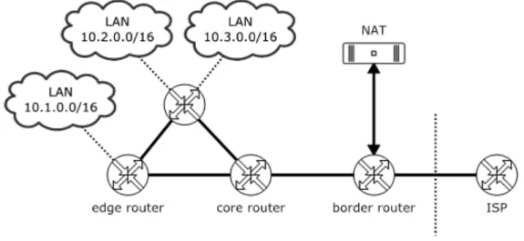
The Campus network at Brno University of Technology (BUT) is divided into several areas. There are a few private networks (RFC1918) in most of them. Source routing technology at a border router is a way to connect these networks to the Internet via a central NAT device. The remaining problem is how to connect a private IP-addressed network to the border router. There are several possible solutions. The easiest way is to route the private networks on the topologically nearest router using standard routing protocols such as Open Shortest Path First (OSPF), Internal Border Gateway Protocol (iBGP), static.
Figure 1: Multiple private LANs connected to a central NAT device
The advantage of this approach is that a user connected to the networks described can use network services within the campus under a unique IP address and therefore all users can always be identified by their IP addresses. This assumes that the network is secured by L2 security features such as Dynamic Host Configuration Protocol (DHCP) snooping and Address Resolution Protocol (ARP) Protect. Translation of private addresses using NAT is implemented along the route from the border router to the ISPs.
2
Campus Network with Two Resilient NATs
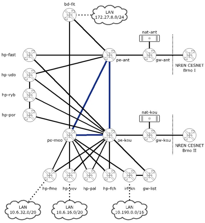
Most ISPs and large organisations use several resilient BGP routers to connect to the Internet. A good example of such an organisation is BUT, which has two border routers in the campus, both based on an HP/3Com platform and each in a different area. A Linux server, directly connected to each border router, implements NAT. Source routing technology at a border router decides whether a packet will be routed to a Linux server with NAT or not. This document describes how to configure the mentioned devices, such as the router or Linux server. Figure 2 shows the topology of the BUT core network with some LANs [1].
3
Border Router Configuration
Routing in the BUT campus network is provided by the OSPF protocol. External connectivity is provided by a pair of BGP routers addressed as in Figure 2 as gw-ant and gw-kou. Each of them is placed in a different area and the failure of one will not affect services on the network, thus providing resilience.
3.1
BGP Configuration
The campus network uses one OSPF area with approximately 340 routes in the routing table. Default gateway routes are imported from the BGP process at border routers to this OSPF area, each route having a different cost. The cost influences the direction of packets from the campus network to the Internet because all routers in the OSPF area have learnt several default routes with different costs. The lowest cost is preferred.
In the opposite direction, from the ISP to the campus network, the traffic flows can be controlled using the AS-path prepends in the BGP configuration. The commands needed to configure an HP/3Com router to provide BGP with these capabilities are described in Section 3.2 [2].
Bgp 197451
router-id 147.229.252.18 preference 9 9 9
import-route ospf 1 synchronization
peer 147.229.252.17 as-number 2852
peer 147.229.252.17 route-policy ISP-EXPORT export peer 147.229.252.17 ip-prefix Pref-ALLOW-DEFAULT import peer 147.229.252.17 password cipher XXXX
The second BGP router is configured similarly. There are differences only in router-id, peer address and some route-policy records.
Bgp 197451
router-id 147.229.253.179 preference 9 9 9
import-route ospf 1 synchronization
peer 147.229.253.180 as-number 2852
peer 147.229.253.180 ip-prefix Pref-ALLOW-DEFAULT import peer 147.229.253.180 password cipher XXXX
The configuration above consists of one routing policy called ISP-EXPORT. The policy describes which networks will be imported from the campus OSPF area to the ISP BGP peer. Only the whole, the campus network 147.229.0.0/16 is imported. This policy also sets the AS-path length, which is used to control the routing direction from the campus network to the ISP. The first router is configured with AS-path length equal to one; the second length is equal to three. Only the default gateway is imported to the campus network. Configuration of routing policies is not as simple, but works as is expected.
Route-policy ISP-EXPORT permit node 0 if-match ip-prefix Pref-ISP-EXPORT apply as-path 197451
ip ip-prefix Pref-ALLOW-DEFAULT index 10 permit 0.0.0.0 0
ip ip-prefix Pref-ISP-EXPORT index 10 permit 147.229.0.0 16 greater-equal 16 less-equal 16
Configuration for the second router differs in the following items:
route-policy ISP-EXPORT permit node 0 if-match ip-prefix Pref-ISP-EXPORT apply as-path 197451 197451 197451
3.2
OSPF Configuration
Configuration of the OSPF protocol is quite straightforward. However, there is one complication in the route importation configuration. The import-route command cannot redistribute a default external route. To do so, it is necessary to use the default-route-advertise command. This allows control of the OSPF cost of an imported default route.
Ospf 1 router-id 147.229.252.18
default-route-advertise cost 50 type 1 import-route direct
import-route bgp area 0.0.0.2
network 147.229.253.0 0.0.0.255 network 147.229.254.0 0.0.0.255
The configuration of the second router is similar. The main difference is in the cost of an advertised default route. The value is set to 150.
3.3
Source Routing Configuration
Source routing allows control of the routing direction based on source IP addresses. This works on incoming traffic which can be matched by an Access Control List (ACL). In BUT’s campus network, all private LANs are created as subnets of 10.0.0.0/8. This traffic is redirected to a NAT server using source routing on a border router. Several NAT servers can be used, but only the first is active. When the IP of the first NAT server disappears from the ARP table, the second one is used.
NAT capability is independent of the traffic path. Only one NAT server is active at a time. The active NAT server is the one connected to the edge router with the lower OSPF cost on the default route. When the NAT, edge router or ISP connection is interrupted, the traffic will be directed using the second edge router and the second NAT server will become active automatically.
Acl number 3001 name PRIVATE-ADDR
rule 0 permit ip source 10.0.0.0 0.255.255.255 policy-based-route RNAT permit node 1
if-match acl 3001
apply ip-address next-hop 147.229.63.3 apply ip-address next-hop 147.229.63.131 interface Vlan-interface639
ip policy-based-route RNAT
Configuration of the second router is similar. The changed order of NAT devices in the policy is the fundamental difference.
Acl number 3001 name PRIVATE-ADDR
rule 0 permit ip source 10.0.0.0 0.255.255.255 policy-based-route RNAT permit node 1
if-match acl 3001
apply ip-address next-hop 147.229.63.131 apply ip-address next-hop 147.229.63.3 interface Vlan-interface534
4
NAT Configuration
Production servers on the BUT campus network are based on the Red Hat Enterprise Linux 6 (RHEL) system [3]. This system uses the iptables firewall for NAT capability. Configuration of a clear RHEL system requires only the setting up of the IP address of server, hostname, iptables and some sysctl values, which is quite simple.
[root@localhost ~]# vim /etc/sysconfig/network
NETWORKING=yes NETWORKING_IPV6=no IPV6_AUTOCONF=no
HOSTNAME=nat-ant.net.vutbr.cz
The server is equipped with an Intel X520 network card with an SFP+ 10 Gbps fibre module that is connected to the border router. It is named eth0 in this system.
[root@nat-ant ~]# vim /etc/sysconfig/network-scripts/ifcfg-eth0
DEVICE=eth0 ONBOOT=yes BOOTPROTO=static IPADDR=147.229.63.3 NETMASK=255.255.255.128 GATEWAY=147.229.63.1
[root@nat-ant ~]# vim /etc/sysconfig/iptables
*nat
:PREROUTING ACCEPT [42:4080] :POSTROUTING ACCEPT [0:0] :OUTPUT ACCEPT [0:0]
-A POSTROUTING –o eth0 –s 10.0.0.0/8 –j SNAT –to-source 147.229.63.3 COMMIT
*filter
:INPUT ACCEPT [0:0] :FORWARD ACCEPT [0:0]
:OUTPUT ACCEPT [0:0]
-A INPUT –m state –state ESTABLISHED,RELATED –j ACCEPT -A INPUT –p icmp –j ACCEPT
-A INPUT –I lo–-j ACCEPT
-A INPUT–-j REJECT–-reject-with icmp-host-prohibited COMMIT
[root@nat-ant ~]# vim /etc/sysctl.conf
net.netfilter.nf_conntrack_max = 524288
5
Conclusion
The purpose of this document is to describe a way to create a central resilient NAT device using OSPF and BGP routing. This approach may be interesting to other campuses whose environment is similar to the BUT campus network.
The technology described has been used in the BUT campus network for two years without any problems. There is a pair of Linux NAT servers with 10 Gbps NICs, each directly connected to a border router HP 5800 with source routing. These systems are capable of providing a service to thousands of clients who can be connected from different LANs within the campus. The main benefit of this solution is in the resiliency of all the network border devices where a failure of one device or a whole area is not critical.
References
[1] Recommended Resilient Campus Network Design, Tomas Podermanski, Vladimir Zahorik, March 2010 (CBPD114, Czech Republic)
www.terena.org/activities/campus-bp/pdf/gn3-na3-t4-cbpd114.pdf
[2] HP A5820X & A5800 configuration guides
http://bizsupport1.austin.hp.com/bc/docs/support/SupportManual/c02648772/c02648772.pdf
[3] Red Hat Enterprise Linux Documentation
Glossary
ACL Access Control List
ARP Address Resolution Protocol
AS Autonomous System
AS-path Autonomous System Path
BGP Border Gateway Protocol
BUT Brno University of Technology
DHCP Dynamic Host Configuration Protocol
iBGP Internal Border Gateway Protocol
IP Internet Protocol
ISP Internet Service Provider
LAN Local Area Network
NAT Network Address Translation
NIC Network Interface Card
NREN National Research and Education Network
OSPF Open Shortest Path First
RFC1918 Address Allocation for Private Internets
RHEL Red Hat Enterprise Linux