STANDALONE PCI INTERFACE PACKAGE
USER’S MANUAL
DOC-039 Rev. 1.1
Copyright © 2009 All Rights Reserved MED Associates, Inc. P.O. Box 319
St. Albans, Vermont 05478 www.med-associates.com
- iii -
TABLE OF CONTENTS
Chapter 1 ... 1
Introduction ...1
The Port System ...1
Chapter 2 ... 2
System Overview ...2
4 Input, 8 Output System ...2
8 Input, 16 Output System ...2
Cable Guide ...2
Hardware Guide ...3
Chapter 3 ... 4
Input Settings ...4
Transition and Level Input Settings...4
Normal and Inverted Input Settings ...5
Chapter 4 ... 6
Wiring Instructions...6
4 Input, 8 Output System ...6
CHAPTER 1
Introduction
The Standalone PCI Interface Package is designed for those applications using a single or limited number of test chambers with no intentions for future expansion. Unlike the modular interface packages, there is no external cabinet and power supply. Connections are made directly to the "standalone" card, which plugs in to a compatible computer. Inputs and outputs are contained on the single card that also provides timed interrupts as required by MED-PC software.
The Standalone PCI Interface Package is available with either 4 Inputs / 8 Outputs or 8 Inputs / 16 Outputs. This manual covers both packages.
WARNING: Do not activate 28 Volts DC with any device connected to the interface card before reading this manual. Certain devices are designed to operate from a short pulse and may be damaged if held on for any extended period of time. Until the function of this card and the software controlling it are understood, it is possible for an output to be held on indefinitely.
The Port System
The port address is hardwired to port 780 for inputs and port 792/793, offset 0 for outputs. MED-PC users should note that in MPC2INST, the MED-PC installation program, the card is the same as a SmartCtrl module. Select DIG-715/716 or DIG-716B depending on the package purchased.
- 2 -
CHAPTER 2
System Overview
4 Input, 8 Output System
This package includes one DIG-750D SmartCtrlTM PCI card, one SG-716 SmartCtrlTM connection panel and one SG-501 28-Volt power supply.
The cables included with the package are one SG-210CB control cable, and two SG-750D power adapter cables. A 25' (7.6 m) power cable (SG-210CP-25) is supplied for the first test station in each group of four. Subsequent stations are daisy chained together with 8' cables (SG-210CP-8).
This system provides four inputs and eight outputs that may be assigned any function and connected to any accessory on the test chamber.
8 Input, 16 Output System
This package includes one DIG-750D SmartCtrlTM PCI card, one SG-716B SmartCtrlTM connection panel and one SG-508 28-Volt power supply.
The cables included with the package are one SG-210CB control cable, and two SG-750D power adapter cable. A 25' (7.6 m) power cable (SG-210CP-25) is supplied for the first test station in each group of four. Subsequent stations are daisy chained together with 8' cables (SG-210CP-8).
This system provides eight inputs and sixteen outputs that may be assigned any function and connected to any accessory on the test chamber.
Cable Guide
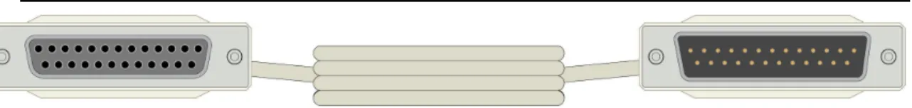
Figure 2.1 - SG-210CB SmartCtrl Cable
Figure 2.2 - SG-219CP Power Conductor Cable (Comes in 8- and 25-foot lengths)
Hardware Guide
Figure 2.4 – DIG-750D PCI Card
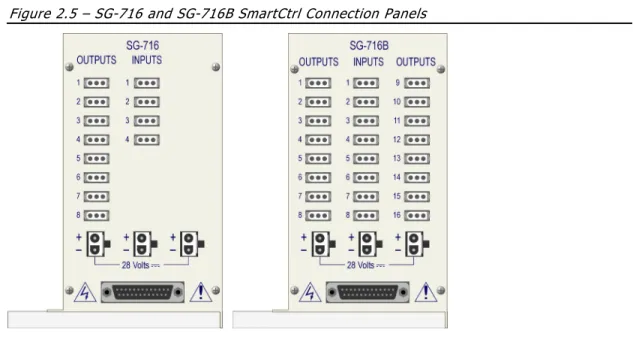
Figure 2.5 – SG-716 and SG-716B SmartCtrl Connection Panels
- 4 -
CHAPTER 3
Input Settings
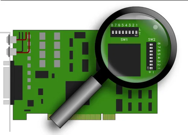
The input settings are selected using the dipswitches labeled SW1 and SW2 located in the upper right corner of the DIG-750D circuit board. The location of the switches is shown in Figure 3.1.
Figure 3.1 – Location of SW1 and SW2 on DIG-750D Card
Transition and Level Input Settings
The row of switches (SW1) used for this setting can be set to L for Level or T for Transition. The default switch placement is Transition, as shown in Figure 3.1.
Transition
This setting provides a single input, no matter how long the input is held. When used with a response lever, for example, this requires the animal to both press and release the lever before another response could be detected. The input may occur on either the press or the release depending on the switch contact (normally open or normally closed) and the input setting (Normal or Invert). Because the input of the card is filtered against switch bounce and latched until polled by the computer, even the shortest contact (or contact break if in Invert mode) will not be missed.
Level
This setting results in an input being detected each time the card is polled, for as long as the input is maintained. (In MED-PC® this occurs on each interrupt and is determined by the resolution setting when Med PC is installed. See the MED-PC® manual for details). This may be desirable when using photobeams, or when timing how long a response lever is held.
Normal and Inverted Input Settings
The row of switches (SW2) used for this setting are labeled + for Normal and - for Inverted. The default switch placement is Normal (+), as shown in Figure 3.1.
Normal
This setting is designed to work with a normally open contact, such as those found in response levers, and will cause an input to occur when the response lever is pressed or the switch contact is closed.
Invert
This setting is designed to work with normally closed contacts, such as those found in pigeon keys, and produces a response when the key is pressed. This setting should be used if an input should occur when a normally open response lever is released or a switch contact is opened. Also use with photobeam inputs if an input is desired when the beam is uninterrupted instead of broken.
- 6 -
CHAPTER 4
Wiring Instructions
The wiring instructions vary slightly between the 4 Input, 8 Output System and the 8 Input, 16 Output System. Refer to the cable guide for illustrations of each cable.
WARNING: Do not activate 28 Volts DC with any device connected to the interface card before reading this manual. Certain devices are designed to operate from a short pulse and may be damaged if held on for any extended period of time. Until the function of this card and the software controlling it are understood, it is possible for an output to be held on indefinitely.
4 Input, 8 Output System
1. Using the SG-210CB cable, connect the 25-pin connector on the bottom of the SG-716 Connection Panel to the 25-pin connector on the DIG-750D card.
2. Using an SG-750D adapter cable and the 8’ SG-210CP cable, connect any of the 28 Volt connectors on the SG-716 Connection Panel to either of the power inputs on the DIG-750D card.
3. Using the other SG-750D adapter cable and the 25’ SG-210CP cable, connect the other power input on the DIG-750D card to the 28 Volt connector on the SG-501 power supply.
4. Using the included AC power cord, connect the SG-501 power supply to a standard wall outlet.
8 Input, 16 Output System
1. Using the 210CB cable, connect the 25-pin connector on the bottom of the SG-716B Connection Panel to the 25-pin connector on the DIG-750D card.
2. Using an SG-750D adapter cable and the 8’ SG-210CP cable, connect any of the 28 Volt connectors on the SG-716B Connection Panel to either of the power inputs on the DIG-750D card.
3. Using the other SG-750D adapter cable, connect the other power input on the DIG-750D card to the SG-508 power supply.
4. Using the included AC power cord, connect the SG-508 power supply to a standard wall outlet.