Software Management Guide
Products Covered
ORiNOCO® AP-800
ORiNOCO® AP-8000
ORiNOCO® AP-8100
Copyright
© 2012 Proxim Wireless Corporation, Milpitas, CA. All rights reserved. Covered by one or more of the following U.S. patents: 5,231,634; 5,875,179; 6,006,090; 5,809,060; 6,075,812; 5,077,753. This guide and the software described herein are copyrighted with all rights reserved. No part of this publication may be reproduced, transmitted, transcribed, stored in a retrieval system, or translated into any language in any form by any means without the written permission of Proxim Wireless Corporation.
Trademarks
ORiNOCO® and the Proxim logo are the trademarks of Proxim Wireless Corporation. All other trademarks mentioned herein are the property of their respective owners.
Disclaimer
Proxim reserves the right to revise this publication and to make changes in the content from time-to-time without obligation on the part of Proxim to provide notification of such revision or change. Proxim may make improvements or changes in the product(s) described in this guide at any time. When using these devices, basic safety precautions should always be followed to reduce the risk of fire, electric shock and injury to persons.
GPL License Note
ORiNOCO® products include, in part, some free software that is developed by Free Software Foundation. A user is granted license to this software under the terms of either the GNU General Public License or GNU Lesser General Public License (See http://www.gnu.org/licenses/licenses.html). This license allows the user to freely copy, modify and redistribute this software and no other statement or documentation from us. To get a copy of this software or for any other information please contact our customer support team (For telephone numbers, see Telephone Support).
OpenSSL License Note
This product contains software developed by the OpenSSL Project for use in the OpenSSL Toolkit (http://www.openssl.org/) and that is subject to the following copyright and conditions:
Copyright (c) 1998-2002 The OpenSSL Project. All rights reserved.
The names "OpenSSL Toolkit" and "OpenSSL Project" must not be used to refer to, endorse, or promote the products or for any other purpose related to the products without prior written permission. For written permission, please contact [email protected].
This software is provided by the OpenSSL Project "as is" and any expressed or implied warranties, including, but not limited to, the implied warranties of merchantability and fitness for a particular purpose are disclaimed. In no event shall the OpenSSL Project or its contributors be liable for any direct, indirect, incidental, special, exemplary, or consequential damages (including, but not limited to, procurement of substitute goods or services; loss of use, data, or profits; or business interruption) however caused and on any theory of liability, whether in contract, strict liability, or tort (including negligence or otherwise) arising in any way out of the use of this software, even if advised of the possibility of such damage.
ORiNOCO® 802.11n Access Points - Software Management Guide
Documentation Version: 4.1 P/N 765-00155, June 2012
Preface . . . 5
1
Introduction . . . 7
Introduction to Wireless Networking . . . 7
About ORiNOCO® 802.11n Access Points . . . 7
Multiple-Input-Multiple-Output . . . 10
2
Management and Monitoring Capabilities . . . 11
Managing and Monitoring Capabilities . . . 11
3
Device Initialization. . . 15
Initialization . . . 15
Logging onto the Web Interface . . . 18
Home Page . . . 20
4
Basic Configuration . . . 23
Basic Configuration . . . 23
Factory Default Configuration . . . 24
Parameters requiring Reboot . . . 25
5
Device Configuration . . . 27
System . . . 28
Network . . . 28
Ethernet . . . 36
Wireless Interface . . . 37
Security . . . 51
Quality of Service (QoS) . . . 61
Virtual Local Area Network (VLAN) . . . 68
Filters . . . 73
DHCP . . . 86
6
Device Management . . . 90
System . . . 90
File Management . . . 93
Services . . . 101
Simple Network Time Protocol (SNTP) . . . 109
Access Control . . . 110
Bridge . . . 120
Network Layer . . . 121
RADIUS . . . 123
Logs . . . 126
Console Commands . . . 127
SNMP V3 Statistics . . . 127
8
Troubleshooting . . . 129
Gigabit PoE Injector (Not supplied) . . . 129
Connectivity Issues . . . 130
Setup and Configuration Problems . . . 132
Recovery Procedures . . . 135
Application Specific Troubleshooting . . . 141
A Frequency Domains and Channels. . . 142
B
Bootloader CLI and Scan Tool . . . 151
C
ASCII Character Chart . . . 153
D Frequently Asked Questions (FAQs) . . . 154
E
Glossary . . . 161
F
Abbreviations . . . 169
G Statement of Warranty . . . 173
Preface
About this Guide
This guide gives a jump-start working knowledge on the ORiNOCO® 802.11n Access Points. It explains the step-by-step procedure to configure, manage and monitor the device by using Web Interface.
Products Covered
Tabulated below are the ORiNOCO® 802.11n Access Points covered in this guide, with the latest software version supported.
Audience
The intended audience for this guide is the network administrator who configures, manages and/or monitors the device, by using the Web Interface.
Prerequisites
You should have a basic working knowledge on Wireless Networks, Local Area Networking (LAN) concepts, Network Access Infrastructures and Client-Server Applications.
Documentation Conventions
ScreenshotsThis guide uses the screenshots of AP-8100, as a base to explain the step-by-step procedures of configuring, managing and monitoring the device by using Web Interface. Based on your device, the screenshots may vary. Hence, we request you to refer to the screenshots that are valid for your device.
This chapter contains the information on the following: • About this Guide
• Products Covered
• Audience
• Prerequisites
• Documentation Conventions
• Related Documents
Product(s) Software Version Supported
ORiNOCO® AP-800 4.0
ORiNOCO® AP-8000 4.0
Device Naming Conventions
Icon Representation
Related Documents
For more information, please refer to the following additional documents that are available at the Proxim’s support site
http://support.proxim.com.
• Quick Installation Guide (QIG): A quick reference guide that provides essential information to install and configure the device.
• Hardware Installation Guide: A guide that provides a hardware overview and details the installation procedures and hardware specifications of ORiNOCO® 802.11n Access Points.
• Reference Guide: A guide that provides essential information on how to configure, manage and monitor the device by using Command Line Interface.
• Safety and Regulatory Compliance Guide: A guide that provides essential information on country specific safety and regulatory norms, to be followed while installing the device.
Naming Convention Description
AP Device Refers to any ORiNOCO® 802.11n AP device
(AP-800 / AP-8000 / AP-8100)
AP-800 Refers to the ORiNOCO® AP-800 device
AP-8000 Refers to the ORiNOCO® AP-8000 device
AP-8100 Refers to the ORiNOCO® AP-8100 device
Name Image Meaning
Note A special instruction that draws the attention of the user.
Important A note of significant importance, that a user should be
aware of.
Caution A warning, that cautions the user of the possible danger.
: Proxim recommends you to visit its support site http://support.proxim.comfor regulatory information and latest product updates.
1
Introduction
1.1 Introduction to Wireless Networking
Wireless Networking refers to the technology that enables two or more computers to communicate by using standard network protocols, but without network cabling, generally referred to Wireless LAN (WLAN). A WLAN is grouping of network components connected by electromagnetic (radio) waves instead of cables. A WLAN basically consists of:
• The network backbone
• End-user devices such as data collection units, handheld computers and laptops • Wireless LAN Access Points
• Wireless cards
• Software that will help you manage the network.
In a WLAN, an Access Point (AP) Device extends the capability of an existing ethernet network to the devices on a wireless network, acting as a bridge between the wired and wireless devices.
A wireless network with atleast one AP Device (either connected to a wired network infrastructure or a wireless backhaul) and a set of wireless devices form a Basic Service Set (BSS). Each BSS is identified by a Service Set Identifier (SSID) which uniquely identifies a WLAN. In a typical network environment, the AP Device functions as a wireless network access point to data and voice networks.
1.2 About ORiNOCO® 802.11n Access Points
Proxim’s ORiNOCO® 802.11n Access Point family comprises of the products tabulated below: This chapter contains information on the following:
• Introduction to Wireless Networking
• About ORiNOCO® 802.11n Access Points
— Salient Features
— Applications
• Multiple-Input-Multiple-Output
Product(s) Description Image
ORiNOCO® AP-800 Proxim’s ORiNOCO® AP-800 is an indoor 802.11n Access Point with dual-band, 3x3 MIMO (Multiple Input and Multiple Output) and a single radio which operates either in 2.4 or 5 GHz. This connectorized device comes with 3 omni-directional antennas.
ORiNOCO® AP-8000 Proxim’s ORiNOCO® AP-8000 is an indoor 802.11n Access Point with dual-band, 3x3 MIMO (Multiple Input and Multiple Output) and dual radio, where one operates in 2.4GHz and other in 5GHz. This connectorized unit comes with 6 omni-directional antennas, 3 per radio. ORiNOCO® AP-8100 Proxim’s ORiNOCO® AP-8100 is an indoor 802.11n Access Point with dual-band, 2x2 MIMO (Multiple Input and Multiple Output) and dual
1.2.1 Salient Features
• Easy operation and installation
• Industry-leading throughput in 802.11b/g/n and 802.11a/n modes in 2.4GHz and 5GHz respectively. • Highest throughput with single radio rates of 150 - 170 Mbps and dual radio rates of 250 - 300 Mbps. • Advanced WPA/WPA2 support for enterprise-grade security.
• Wi-Fi certified to interoperate with any Wi-Fi certified client access product. • Provides wall mounting or ceiling option for flexible device installation. • Distributed WLANs with Centralized Management.
• Management through a Web Interface (HTTP), Command Line Interface (CLI), Simple Network Management Protocol (SNMP) and Network Management System (ProximVision ES v2.3 and above)
1.2.2 Applications
1. Multiple high definition IP-surveillance cameras used for monitoring airports, offices, restaurants, warehouses, etc., can be monitored and managed by using a single AP Device.
2. Proxim’s AP Devices exhibit a secure data transfer via high speed network links and over-the-air encryption of data. 3. Enterprise Connectivity:
Delivering a secure, flexible, scalable and reliable enterprise class 802.11n standard Data, Voice, and Video for small and medium Enterprise WLAN deployments, our AP Device can serve multiple service sets with:
— Multiple SSID Assignment: Multiple wireless clients connected to a single AP Device are grouped together as different service sets and every service set is assigned an independent SSID, allowing you to maintain maximum number of groups under a single Virtual Access Point (VAP) network.
— Single SSID Assignment: Different wireless clients belonging to different service sets (SSIDs) can access the wireless network from one single AP Device with a single SSID.
— RADIUS VLAN Assignment: In addition to the manual VLAN assignment, every wireless client / service set connected to a single AP Device is assigned a specific VLAN ID via a pre-configured RADIUS server, reducing the load of manually configuring the VLAN parameters of each wireless client.
4. Seamless client roaming for both data and voice (VoIP):
Multiple wireless clients can connect to a single AP Device, or they can move between multiple AP Devices located within the same vicinity. As wireless devices move from one coverage cell to another, they maintain the network connectivity.
Figure 1-2 Seamless Client Roaming
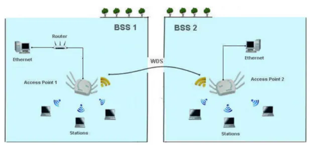
5. Extended Coverage Areas:
Proxim’s high capacity, 802.11n AP Devices support Wireless Distribution System (WDS), that helps you establish a wireless communication between two AP Devices or two Basic Service Sets (BSS), thus allowing you to extend the WLAN or an access point coverage to wide areas.
1.3 Multiple-Input-Multiple-Output
ORiNOCO® 802.11n AP Devices support Multiple-Input-Multiple-Output (MIMO) antenna technology that uses multiple antennas at both the transmitting end and receiving end to improve communication performance. The underlying technology of these access point radio(s) are based on a combination of MIMO and OFDM (Orthogonal Frequency Division Multiplexing). MIMO-OFDM combination radios solve interference, fading and multipath problems. Having multiple receivers at the receiving end, increases the amount of received power and also reduces multipath problems by combining the received signals for each frequency component separately. Hence, MIMO significantly improves the overall gain.
MIMO also uses Spatial multiplexing transmission technique to transmit independent and separately encoded data signals from each of the multiple transmit antennas while reusing or multiplexing in the space dimension. These independent data signals are called Spatial streams. The transmitting end of the device uses multiple radio Tx chains and signal paths to simultaneously transmit different data streams, whereas the receiving end combines the Rx signals resulting in higher throughput.
By increasing the number of receiving and transmitting antennas, the throughput of the channel increases linearly resulting in high spectral efficiency.
2
Management and Monitoring Capabilities
2.1 Managing and Monitoring Capabilities
A Network Administrator can use the following interfaces to configure, manage and monitor the device. • Web (HTTP/HTTPS) Interface
• Command Line Interface (CLI) (Terminal Emulator Programs) • Simple Network Management Protocol (SNMP) v1/v2c/v3 • ProximVision ES (PVES) [v2.3 and above]
2.1.1 Web (HTTP/HTTPS) Interface
The HTTP interface provides an easy access to configuration settings and network statistics from any computer on the network. You can access the HTTP Interface via your LAN (switch, hub and so on), internet, or with an ethernet cable connected directly to your computer’s ethernet Port.
HTTPS interface provides an HTTP connection over a Secure Socket Layer (SSL). HTTPS allows the user to access the device in a secure fashion by using SSL over port 443. The device supports SSLv3 with a 128-bit encryption certificate maintained by the device for secure communication between the device and the HTTP client. All communications are encrypted by using the server and the client-side certificate.
2.1.2 Command Line Interface (CLI) (Terminal Emulators)
The Command Line Interface (CLI) is a text-based configuration utility that supports a set of keyboard commands and parameters to configure, manage and monitor the device. You can enter command statements, composed of CLI commands and their associated parameters. Statements may be issued from the keyboard for real time control, or from scripts that automate the configuration. For example, when downloading a file, an administrator enters the download CLI Command along with the IP Address, file name, and file type parameters.
2.1.2.1 Serial Connection
You can access the CLI over a HyperTerminal serial connection. HyperTerminal is a program that you can use to connect to other Computers, Telnet Sites, Bulletin Board Systems (BBS), Online Services, and Host Computers, by using either a modem or a null modem cable.
If you are using an RS-232 cable, verify the following information in the HyperTerminal serial port setup: This chapter contains information on the following:
• Managing and Monitoring Capabilities
— Web (HTTP/HTTPS) Interface
— Command Line Interface (CLI) (Terminal Emulators)
— Simple Network Management Protocol (SNMP)v1/v2c/v3 — ProximVision ES (PVES)
:
• If you are using Windows 7 operating system, then use Terminal Emulator programs for serial connection.
• HyperTerminal Serial Connection is not applicable to AP-8100, as it does not have a serial port. However, you can access the CLI via your LAN (switch, hub and so on), internet, or with an ethernet cable connected directly to your computer’s ethernet Port.
2.1.2.2 Telnet
You can access the device through CLI by using Telnet. With Telnet, you can communicate with the device through your LAN (switch, hub and so on), Internet, or with an ethernet cable connected directly to your computer’s ethernet port.
2.1.2.3 Secure Shell (SSH)
You can securely access the device through CLI by using Secure Shell (SSH). The device supports SSH version 2, for secure remote CLI (Telnet) sessions. SSH provides strong authentication and encryption of session data. The SSH server has host keys - a pair of asymmetric keys (a private key that resides on the device) and a public key that is distributed to clients that need to connect to the device. Clients need to verify that it is communicating with the correct SSH server.
: For details on configuring the device through CLI, please refer to the ORiNOCO® 802.11n Access Points - Reference Guide.
2.1.3 Simple Network Management Protocol (SNMP)v1/v2c/v3
You can also configure, manage and monitor the device by using the Simple Network Management Protocol (SNMP). This requires an SNMP Manager Program (sometimes called MIB browser) or a Network Manager program using SNMP. The device supports the following Management Information Base (MIB) files that describe the parameters that can be viewed and/or configured over SNMP:
• PXM-SNMP.mib
• RFC-1213.mib • RFC-1215.mib • RFC-2571.mib • RFC-2790.mib • RFC-3412.mib • RFC-3414.mib • IEEE 802.11mib
Port COM1 (default)
Baud Rate 115200
Data 8-bit
Parity None
Stop 1-bit
The Enterprise MIB defines the read and read-write objects that can be viewed or configured by using SNMP. These objects correspond to most of the settings and statistics that are available with the other management interfaces. All Read-Only (RO) and Read-Write (RW) parameters supported by the IEEE802dot11-MIB are as tabulated below.
These MIB files are available on Proxim's website at http://support.proxim.com. You need to compile one or more of the above MIBs into your SNMP program’s database before you can manage the device by using SNMP. The MIB can be opened with any text editor, such as Microsoft Word, Notepad, or WordPad.
S.No. MIB Object Name Access
(RO / RW)
1 dot11StationID RO
2 dot11PrivacyOptionImplemented RO
3 dot11PowerManagementMode RO
4 dot11DesiredSSID RW
5 dot11DesiredBSSType RO
6 dot11BeaconPeriod RW
7 dot11DTIMPeriod RW
8 dot11MultiDomainCapabilityImplemented RO
9 dot11MultiDomainCapabilityEnabled RO
10 dot11CountryString RO
11 dot11AuthenticationAlgorithmsIndex RO
12 dot11AuthenticationAlgorithm RO
13 dot11AuthenticationAlgorithmsEnable RO
14 dot11MACAddress RO
15 dot11RTSThreshold RW
16 dot11FragmentationThreshold RW
17 dot11ManufacturerID RO
18 dot11ProductID RO
19 dot11ResourceTypeIDName RO
20 dot11manufacturerName RO
21 dot11manufacturerProductName RO
22 dot11PHYType RO
23 dot11CurrentRegDomain RO
24 dot11TempType RO
25 dot11RegDomainsSupportedIndex RO
26 dot11RegDomainsSupportedValue RO
27 dot11SupportedDataRatesTxIndex RO
28 dot11SupportedDataRatesTxValue RO
29 dot11SupportedDataRatesRxIndex RO
30 dot11SupportedDataRatesRxValue RO
: For details on configuring the device through the SNMP Interface, please refer to the ORiNOCO® 802.11n Access Points - Reference Guide.
2.1.4 ProximVision ES (PVES)
ProximVision ES (commonly known as PVES) is Proxim’s Network Management System that helps to manage and administer your wireless network effectively and efficiently. ProximVision ES combines industry-leading functionality with an intuitive user interface, enabling Network Administrators and Help Desk staff to support and control a wireless network.
ProximVision ES offers you a single intelligent console from which you can manage, monitor, analyze and even configure your device. For more information, see ProximVision ES user guide available at http://support.proxim.com.
3
Device Initialization
3.1 Initialization
You can initialize the device either through CLI commands, Web Interface or an SNMP Interface.
• To initialize the device by using CLI commands, connect a serial RS-232 cable to the Serial Port of the device.
: AP-8100 does not have a serial port. However, you can initialize, configure, manage and monitor the device through CLI commands via Telnet/SSH.
• To initialize the device by using Web or SNMP interface, connect an ethernet cable to the Ethernet Port of the device.
For all the modes of connection, you will need to configure the IP address of the device. As each network is different, a suitable IP address on the network must be assigned to the device. This IP address helps you to configure, manage and monitor the device through the Web Interface, SNMP, or Telnet/CLI.
The device can either have a static IP or dynamic IP address. By default, the device obtains its IP address automatically through DHCP (dynamic IP address); or else, you must set the IP Address manually (static IP address).
To access the HTTP interface and configure the device, the device must be assigned an IP address, which is valid on its ethernet network. By default, the IP Address type is set to Dynamic. If there is no response from the DHCP server, then the device will fall back to the IP Address 169.254.128.132.
3.1.1 ScanTool
Proxim’s ScanTool (Answer ID 1735) is a software utility that runs on Microsoft's Windows machine. By using ScanTool, you can
• Scan devices within the local IP subnet, which respond to the ScanTool.
: To scan a device in Bootloader mode by using ScanTool, see Bootloader CLI and Scan Tool.
• Obtain device’s IP address
• Modify device’s IP configuration parameters (IP Address, Address Type, Gateway, etc.) • Switch between the network adapters, if there are multiple network adapters in the system.
This chapter contains information on the following: • Initialization
— ScanTool
— Initialize the Device by using ScanTool
— Modifying the IP Address • Logging onto the Web Interface
• Home Page
— Commit
:
• The user may need to disable Windows Firewall for ScanTool to function or to detect the radio.
• ScanTool works only for the Proxim products.
3.1.2 Initialize the Device by using ScanTool
To scan and locate the devices on a network by using ScanTool, do the following: 1. Power on, or reset the device
2. To download Proxim’s ScanTool, log on to Proxim’s support site at http://support.proxim.com and search for ScanTool with (Answer ID 1735). Upon successful download, double-click the ScanTool icon on the Windows desktop to launch the program (if the program is not already running).
3. If your computer has more than one network adapter installed, you will be prompted to select the adapter that you want ScanTool to use. You can use either an ethernet or a wireless adapter. Select an adapter and click OK.
4. The Scan List screen appears.
Figure 3-1 Scan List
5. ScanTool scans the subnet and displays a list of detected devices in the Scan List. You can change your adapter setting at any time by clicking the Select Adapter on the Scan List screen.
6. The screen contains the following information: • MAC Address
• System Name
• IP Address
• Uptime
• System Description: System Description contains the following information. — Device Description (ORiNOCO® AP-8100-WD)
— Firmware Version v4.X.Y (v4.1.0)
— Serial Number (SN-SN000000000000121212) — Bootloader Version (BL-V1.0.2)
7. Click Select Adapter, to change the adapter settings.
8. Locate the MAC address of the device you want to initialize from the Scan List and click Web Config to logon to the Web Interface. See Logging onto the Web Interface
:
• If device does not appear in the Scan List, click Rescan in the Scan List to update. If the device still does not appear in the list, see Troubleshooting.
• Note that after rebooting the device, it may take up to five minutes for the device to appear in the Scan List.
3.1.3 Modifying the IP Address
The IP address assigned to the device can be obtained and, if required, can be changed to the IP address that is appropriate on the network. The ScanTool automatically detects the devices installed on the network segment, regardless of the IP address, and enables the configuration of each device’s IP settings
By using ScanTool, you can change the IP address of the device as explained below:
1. Select the device details from the Scan List and click Change. A Change screen appears as shown in the following figure.
Figure 3-2 Modifying the IP Address
2. The system automatically generates the MAC address, System Name, TFTP Server IP Address and Image File Name of the device.
3.1.3.1 Assigning the IP Address Manually
1. Select the IP Address Type as Static and enter the appropriate IP Address, Subnet Mask, and the Gateway IP Address parameters.
3.1.3.2 Assigning the IP Address Dynamically
: Before setting the IP Address Type as Dynamic, ensure there is a DHCP server on the network.
To change the IP Address type from Static to Dynamic, follow these steps:
1. Select the IP Address Type as Dynamic. The IP Address, Subnet Mask and the Gateway IP Address fields get disabled.
2. Enter the SNMP Read/Write password in the Read/Write Password field. By default, it is public. 3. Click OK to save the changes.
4. Click Rescan to verify the changes applied.
: The device automatically reboots after clicking OK.
To log on to the Web Interface, click Web Config.The user is then prompted to enter its username and password. For more information on how to login, please see Logging onto the Web Interface
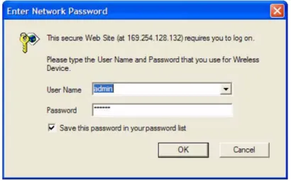
3.2 Logging onto the Web Interface
Once the device is connected to your network, use a web browser to configure, manage and monitor the device. Enter the device IP address (For example http://169.254.128.132) in the address bar or access the Web Interface by using ScanTool. The user is prompted to enter the username and password. The default User Name is admin and Password is public.
Figure 3-3 Login Screen :
• For security purposes, it is recommended to change the default Password to restrict unauthorized access to the device.
• Depending on the settings made during the device initialization, the IP address may be either a dynamic IP address assigned by a network DHCP server or a static IP address which is manually configured. Refer to ScanToolfor information on how to determine the device’s IP address and manually configure a new IP address.
• If the connection is slow or unable to connect, use the Internet Explorer Tools option to ensure that you are not using a proxy server for the connection.
• If you are unable to log on to the configuration pages by using default user name and password, please check with the administrator or follow Forced Reload procedures.
• If using Internet Explorer, and you enter wrong password consecutively for three times, the HTTP session will get disconnected. If case of other browsers, the login screen will reset until you enter the correct password.
• In the Internet Explorer, to get best results, navigate to Tools > Internet Options > General. Click Settings in the Browsing History and select “Every visit to the webpage”.
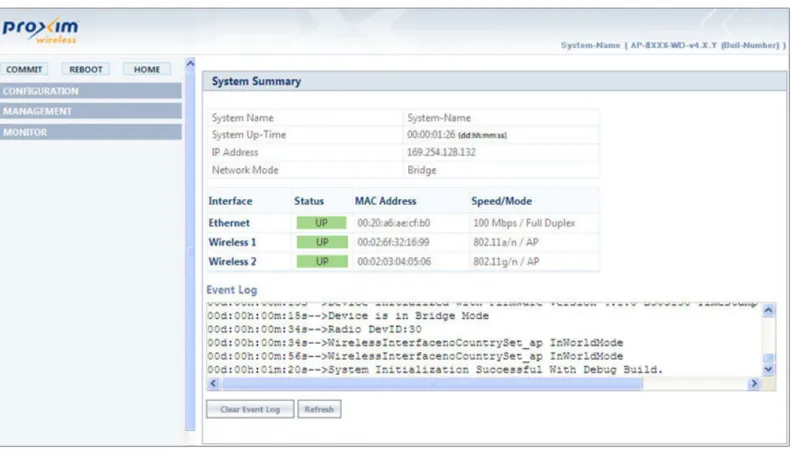
3.3 Home Page
Upon successful login, the Home Page screen appears.
Figure 3-5 System Summary
The home page contains the following information:
1. Device Description: The device description is displayed on the top-right corner of the home page. It displays the system-name, device type, regulatory domain, latest software version supported and firmware version loaded on the device.
2. System Summary: The System Summary screen displays the summary of system information such as System Name, IP Address, Network Mode, Interface Status, MAC Address, Event Log, etc.
3. COMMIT: See Commit
4. REBOOT: See Reboot
5. HOME: Displays the System Summary Screen.
6. CONFIGURATION: The CONFIGURATION tab allows the user to configure the set of parameters required for a device to be operational and establish link in the network. For more details, see Device Configuration.
7. MANAGEMENT: The MANAGEMENT tab allows the user to manage the device. For more details, see Device Management
8. MONITOR: The MONITOR tab allows the user to monitor the device. For more details, see Device Monitoring
3.3.1 Commit
COMMIT operation is used to apply the configuration changes to the device. When changes are made to the configuration parameters of the device, the changes will not take effect, until the COMMIT is clicked. Some parameters may require system reboot for the changes to take effect. On clicking COMMIT, the system evaluates all the configuration dependencies and displays the configuration status.
Before applying commit, the system displays a confirmation message, as shown in the following figure:
Figure 3-6 Commit
Click OK, if you wish to commit the changed parameters. On successful Commit operation, the following screen appears:
Figure 3-7 Commit Status
If the configured parameters requires reboot, on committing the following screen appears.
Figure 3-8 Commit Status with Reboot Message
3.3.2 Reboot
Reboot operation is required for any change in the key parameters to take effect. For example, settings such as configuring the Radio Mode, IP Address, and Network Mode need reboot to take effect. See Parameters requiring Reboot, for more details. On clicking REBOOT, system displays a confirmation window as shown below.
Figure 3-9 Reboot
Click OK, if you want to reboot the device.
:
• Every parameter requiring REBOOT upon its configuration, is marked with a red asterisk and it is recommended to reboot the device immediately after modifying a rebootable parameter.
• If the device does not reboot and redirect you to the HOME Page within 2 minutes, then we recommended you to check the network connectivity and try accessing the page later.
4
Basic Configuration
4.1 Basic Configuration
Tabulated below are the parameters to be configured to operate the AP device at a basic level: This chapter contains information on the following:
• Basic Configuration
• Factory Default Configuration
• Parameters requiring Reboot
Parameter Description
IP Address If you have DHCP Server on your network, then set the Address Type as Dynamic. When set to Dynamic, the device gets its IP Address from the DHCP Server. If there is no response from the DHCP Server, then the device will fall back to 169.254.128.132.
If you do not have the DHCP Server on your network, change the Address Type as Static. For details on how to configure the Address Type and the IP address, refer to IP Configuration
Country Code Select a country from the drop down menu. For more details on how to configure the Country Code, refer to Properties
Radio Mode By default, the radio mode on both Radio1 (Interface1) and Radio 2 (Interface 2) is set to AP. For details on how to configure the radio mode, refer to Properties
Operational Mode Default Operational Mode set on both the radios, is as tabulated below:
For details on how to change the operational mode, refer to Properties
Current Bandwidth By default, the current bandwidth is set to 40 MHz. For details on how to change the current bandwidth, refer to Properties
: All the interface (radio) 2 parameters discussed in this chapter are applicable only to a dual-radio device.
Device Type Operational Mode
Radio 1 Radio 2
AP-800 802.11g/n Not Applicable
AP-8000 802.11a/n 802.11g/n
Ensure to COMMIT the configured changes and REBOOT the device.
4.2 Factory Default Configuration
SSID Default SSID set on both the radios, is as tabulated below:
For details on how to change SSID, refer to Virtual Access Point (VAP)
Security By default, the security is set to None. For details, refer to Wireless Security
Parameter Default Values
User Name admin
Password public
System Name System-Name
Network Mode Bridge
IP Address Assignment Type Dynamic
Fall Back IP Address 169.254.128.132
Subnet Mask 255.255.0.0
Gateway IP Address 169.254.128.133
Link Integrity Status Disabled
STP Status Disabled
Radio Mode Radio1: AP
Radio2: AP
Radio Status Enabled
Country Code NoCountry (World Regulatory Domain)
US (US Regulatory Domain) JP (JP Regulatory Domain)
Device Type SSID
Radio 1 Radio 2
AP-800 My Wireless Network 1_1 Not Applicable
AP-8000 My Wireless Network 1_1 My Wireless Network 2_1
4.3 Parameters requiring Reboot
Operational ModeCurrent Bandwidth 40 MHz
VAP SSID
Wireless Distribution System (WDS)
Disabled
Local MAC Authentication Disabled
RADIUS MAC Authentication Disabled
RADIUS Accounting Disabled
RADIUS Server Profile Enabled with Profile Name “Default Radius”
VLAN Status Disabled
RADIUS VLAN Status Disabled
Security Profile Name AP Security
QoS Profile Name Default
Security Auth Mode None
Global Filtering Disabled
Proxy ARP Status Disabled
Packet Forwarding Disabled
DHCP Server Status Disabled
SNMP Management Interface Enabled with SNMPv1-v2c
Telnet Management Interface Enabled with login “admin” and password “public”
Device Type
Operational Mode (Supported Frequency Band)
Radio 1 Radio 2
AP-800 802.11g/n (2.4 GHz) Not Applicable
AP-8000 802.11a/n (5 GHz) 802.11g/n (2.4 GHz)
AP-8100 802.11a/n (5 GHz) 802.11g/n (2.4 GHz)
Device Type
SSID
Radio 1 Radio 2
AP-800 My Wireless Network 1_1 Not Applicable
AP-8000 My Wireless Network 1_1 My Wireless Network 2_1
Parameter(s) Web Page(s)
Address Type
CONFIGURATION - > Network - > IP Configuration
IP Address Subnet Mask Gateway IP Address
DNS Primary IP and Secondary IP Address
Radio Mode
CONFIGURATION - > Wireless - > Interface 1/ Interface 2 - > Properties
Country Code Operational Mode Current Bandwidth
Frequency Extension CONFIGURATION - > Wireless - > Interface 1/ Interface 2 - > 11n Properties
Update Firmware (HTTP / TFTP) MANAGEMENT - > File Management - > Update Firmware
Update Configuration (HTTP / TFTP)
MANAGEMENT - > File Management - > Update Configuration
Password
MANAGEMENT - > Services - > HTTP / HTTPS
HTTP HTTP Port HTTPS Password
MANAGEMENT - > Services - > Telnet / SSH
Telnet Telnet Port Telnet Sessions SSH
SSH Port SSH Sessions SNMP
MANAGEMENT - > Services - > SNMP
Version Read Password Read / Write Password
5
Device Configuration
Note that you can also configure the device by using CLI and SNMP interfaces. Hence, we recommend you to also refer the
ORiNOCO® 802.11n Access Points - Reference Guide.
This chapter explains the step-by-step procedure to configure the following features on the device, by using Web Interface:
• System
• Network
— IP Configuration
— Link Integrity
— Spanning Tree Protocol (STP)
• Ethernet
• Wireless Interface
— Interface 1 — Properties
— 11n Properties
— Virtual Access Point (VAP)
— Interface 2 • Security
— Wireless Security — RADIUS
— MAC Access Control • Quality of Service (QoS)
— Enhanced Distributed Channel Access (EDCA) — 802.1d to IP DSCP
— 802.1d to 802.1p — QoS Profile
— QoS Policy
• Virtual Local Area Network (VLAN)
— VLAN Ethernet Configuration • Filters
— Protocol Filters
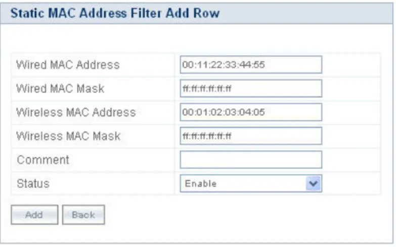
— Static MAC Address Filters
— Advanced Filters — TCP/UDP Port Filters
— Storm Threshold Filters — Packet Forwarding
• DHCP
5.1 System
The System feature enables you to configure system specific information. Navigate to CONFIGURATION > System. The
System screen appears.
Figure 5-1 System
Tabulated below are ‘System’ parameters and the method to configure the configurable parameters:
Click OK and COMMIT, to save the configured parameters.
5.2 Network
The Network feature displays the network specific information of the device.
To view the network mode, navigate to CONFIGURATION > Network. The Network Configuration screen appears.
Figure 5-2 Network Configuration
The device supports only Bridge mode.
5.2.1 IP Configuration
The IP Configuration feature enables you to configure the TCP/IP settings of the device on a network. Navigate to
CONFIGURATION > Network > IP Configuration. The Network IP Configuration screen appears.
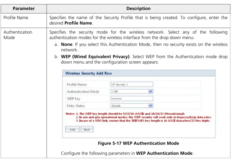
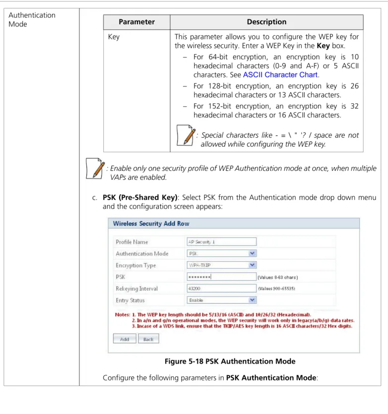
Parameter Description
System Name Specifies the name assigned to the device. To assign a name to the device, enter a name in the System Name box. You can enter a name of maximum 64 characters.
Network Mode Specifies the network mode of the device. The device supports only Bridge mode.
: All the interface (radio) 2 parameters discussed in this chapter are applicable only to a dual-radio device.
Figure 5-3 Network IP Configuration
Tabulated below are ‘Network IP’ parameters and the method to configure the configurable parameters:
Parameter Description
Address Type By default this parameter is set to Dynamic. When set to dynamic, the device will obtain IP settings from a network Dynamic Host Configuration Protocol (DHCP) server automatically during the boot-up.
If you do not have a DHCP server or if you want to manually configure the device IP address, set this parameter to Static.
IP Address Specifies the IP Address of the device. When the address type is set to Dynamic, this parameter is read-only and displays the device’s current IP address obtained from the DHCP server. The device will be set to the default IP address 169.254.128.132, if the device cannot obtain the IP address from a DHCP server.
If the Address Type is set to Static then you will have to manually enter the IP Address in the
IP Address box.
Subnet Mask Specifies the device subnet mask. When the address type is set to Dynamic, this parameter is read-only and displays the device current subnet mask obtained from the DHCP server. The device will be set to the default subnet mask 255.255.0.0, if the device cannot obtain the subnet mask from a DHCP server.
If the Address Type is set to Static then you will have to manually enter the subnet mask in the Subnet Mask box.
Gateway IP Address Specifies the IP address of the device gateway. When address type is set to Dynamic, this parameter is read-only and displays the IP address of the device gateway. The device will be set to the default Gateway IP address 169.254.128.133, if it cannot obtain the gateway IP address from a DHCP server.
Click OK and COMMIT, to save the configured parameters.
: If you have changed any of the TCP/IP parameters, then reboot the device.
5.2.2 Link Integrity
Link Integrity helps you to check connectivity between the AP device and its pre-configured servers (routers, gateway devices and other devices in the vicinity), by sending ICMP (Internet Control Message Protocol) echo probes periodically. If the device receives an acknowledgment from a server within the configured time interval, then the link between that server and the AP device is active and the link integrity status is set to UP, otherwise it is set to DOWN.
If atleast one server responds back, then the over all Link Status is set to UP and the device performs standard AP functionality. If all the servers configured fail to respond, then the over all Link Status is set to DOWN and all the VAPs enabled in AP mode are disabled. (VAPs in WDS mode remain unaffected. See Virtual Access Point (VAP)). The VAPs in AP mode resume as Link Status is set to UP.
Navigate to CONFIGURATION > Network > Link Integrity. The Link Integrity screen appears.
Figure 5-4 Link Integrity
Primary IP Address Specifies the IP Address of the Primary DNS Server. When the address type is set to
Dynamic, this parameter is read-only and displays the DNS Primary IP Address obtained from the DHCP server.
If the Address Type is set to Static then you will have to manually enter the IP Address in the
Primary IP Address box. Secondary IP
Address
Specifies the IP Address of the Secondary DNS Server. When the address type is set to
Dynamic, this parameter is read-only and displays the DNS Secondary IP Address obtained from the DHCP server.
If the Address Type is set to Static then you will have to manually enter the IP Address in the
Tabulated below are ‘Link Integrity’ parameters and the method to configure the configurable parameters
:
Click OK and COMMIT, to save the configured parameters.
5.2.2.1 Link Integrity Server Table
The Link Integrity Server Table displays the following details of all the pre-configured server(s):
Parameter Description
Status Specifies the status of the link integrity feature on the device.
By default, it is disabled. To enable, select Enable from the drop down menu.
Polling Time Specifies the time interval, during which the device will check the link integrity with its configured server(s) by sending the ICMP echo probes.
By default, the Polling Time taken is 30 seconds. To configure, enter the time interval between 5 seconds - 180 seconds.
Offline Polling Time Specifies the time interval, during which the device will send the ICMP echo probes to server(s) in offline mode (When the Link status is DOWN).
By default the Offline Polling Time taken is 1 second. To configure, enter the time interval between 1 second - 5 seconds
Polling Retries Specifies the number of attempts made by the device in sending the ICMP echo probes to the server(s), before declaring the overall link status as DOWN.
By default, the Polling Retries taken is 2. To configure, enter the number of attempts between 1-10
Link Status Specifies the connectivity status between a server and a device. Link Status can either be UP, DOWN or NONE.
– UP: Specifies the status of the link when AP device receives the server’s acknowledgment.
– DOWN: Specifies the status of the link when AP device does not receive the server’s acknowledgment.
– NONE: Specifies the status of the link when the AP device is trying to connect to the server(s), that is when the Link Status is neither UP nor DOWN.
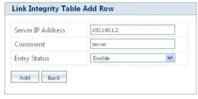
Parameter Description
Server IP Address Specifies the IP Address of the configured server. Comment Specifies the user comment on the configured server.
Entry Status Specifies the entry status of the server. By default, it is disabled. To configure, set the entry status as Enable/Disable/Delete from the drop down menu.
– Enable: Enables the server added. – Disable: Disables the server added. – Delete: Deletes the server added.
Link Integrity Table - Add Row
To enable link integrity on the AP device, atleast one entry should be added to the Link Integrity Server Configuration Table. To add an entry, do the following:
1. Click Add in the link integrity screen, theLink Integrity Table - Add Row screen appears:
Figure 5-5 Link Integrity Table - Add Row
2. Configure all the parameters and click Add,to save the added entry.
:
• A maximum of five servers can be added.
• Atleast one server should be added to the table, to enable the link integrity feature on the device.
5.2.3 Spanning Tree Protocol (STP)
The Spanning Tree Protocol (STP) helps to avoid bridged loops in a wireless network and ensures a loop-free topology for bridged LAN (connected on both Wireless and Ethernet interface). Following is the step-by-step procedure on how STP feature works:
a. Disable: In this state, STP is disabled and no traffic is allowed through Wireless and Ethernet interfaces of the bridged LAN.
b. Listening: When STP is enabled, the AP devices exchange Bridge Protocol Data Unit (BPDU) packets in listening state. These BPDU packets contain Bridge Priority and MAC Address information, based on which a Root bridge and Designated Bridge are selected.
• Root Bridge: It is the device that has the lowest MAC Address or highest priority. Based on a Root Bridge,the shortest low cost path is selected and alternate high cost paths are blocked, therefore avoiding loops on the network. Root Bridge transmits the network topology information continuously to other bridges on the network.
• Designated Bridge: It is the device closest to the Root Bridge and is responsible for forwarding the data towards the root port of the root bridge. Designated Bridge determines the shortest low cost path to the destination, via root port. All the other devices in the network other than Root Bridge, act as Designated Bridge.
c. Learning: Once the Root Bridge and Designated Bridge are selected, all the devices learn and update the Bridge Priority and MAC address information in their learn table. Designated Bridge determines the shortest low cost path to via root port, to forward the packets to the destination.
d. Blocking: After selecting the low cost path, the device blocks and disables all the other high cost paths active on other interfaces. Once the path is blocked, no traffic is allowed via that high cost path.
e. Forwarding: The device easily forwards the data packet to the destination via single low cost path selected, with zero loops and interference on the bridged network.
: The state of the port must change from blocking state to listening and learning state, before it can change to the forwarding state.
Example: Let us consider a network with three Bridges (Bridge 1, Bridge 2 and Bridge 3)
Figure 5-6 STP Topology
• Bridge 1 and Bridge 2 are connected via both Wireless and Ethernet interface, while Bridge 3 is connected to Bridge 1 and Bridge 2 only via Wireless interface.
• To avoid a network loop between Bridge 1 and Bridge 2, the STP feature should be enabled on all the devices. • Once the STP feature is enabled, Bridge 1, Bridge 2 and Bridge 3 change from Disable state to Listening stateand
start exchanging the BPDU packets. Bridge 3, having the highest priority and smallest MAC Address, acts as the Root Bridge, and Bridge 1 and Bridge 2 act as Designated Bridges.
• The Designated Bridges (Bridge 1 and Bridge 2) then determine the shortest low cost path via root port, to forward the data from bridge 1 to bridge 2, on a loop- free bridged network.
• Bridge 1 and Bridge 2 switch from Listening state to Learning statewhere they update the learn tables and enable the shortest low cost path determined.
• The STP enabled Bridge 2 then changes from Learning state to Blocking state and blocks all the longest high cost paths, near both wireless and ethernet interfaces.
• Bridge 1 finally changes from Learning stateto Forwarding state and forwards the data packet to Bridge 2 through the shortest low cost path (via the root port of Bridge 3) enabled, avoiding loops on the network.
Figure 5-7 STP Configuration
Tabulated below are ‘STP’ parameters and the method to configure the configurable parameters:
Parameter Description
Status Specifies the status of the STP feature on the AP device.
By default, STP is disabled. To enable, select Enable from the drop down menu.
Bridge Priority Specifies the priority assigned to a bridge.
By default, a bridge is assigned with a priority of 4096. To configure, enter a value between 0 - 61440 (as multiples of 4096).
: Bridge assigned with the lowest value gets the highest priority, and is selected as Root Bridge.
Maximum Age Specifies the maximum time period for an AP device to hold the BPDU packet before discarding it.
By default, it is 20 seconds. To configure, enter the Maximum Age between 6 seconds - 40 seconds.
Hello Time Specifies the time interval in which the Root Bridge sends the BPDU packets periodically. By default, it is 2 seconds. To configure, enter the Hello Time between 1 second - 10 seconds.
Forward Delay Specifies the time interval, for the bridge to be in Learning state and Listening state. By default, it is 15 seconds. To configure, enter the Forward Delay time between 4 seconds - 30 seconds.
:Forward Delay depends on the Maximum Age.
VAP Name Specifies the name of the VAP enabled with the STP feature.
Port State Specifies the state of the port, in which the AP device with STP feature is currently functioning. Port State varies between Disabled, Listening, Learning, Blocking and
Forwarding.
Port Priority Specifies the priority assigned to a port, to participate in the STP process and act as a Root Port (port maintaining connectivity with root bridge, on the interface of an AP device). When the AP device experiences a tie in determining the low cost path towards root, it uses the Port Priority value as a tiebreaker.
By default, Port Priority taken is 16. To configure, enter the a value in the range of 0 - 48 (as multiples of 16).
: The state of the root port is always in Forwarding state.
Port Path Cost Specifies the cost of the path. Path cost is a pre-determined value of the IEEE 802.11 standards, based on the bandwidth and speed on that path. The port with the lowest path cost to the root bridge becomes the root port, gaining high priority.
Click OK and COMMIT, to save the configured parameters.
5.3 Ethernet
This feature enables you to view and configure the speed and transmission mode of the ethernet interface. Navigate to
CONFIGURATION > Ethernet. The Ethernet Interface Properties screen appears.
Figure 5-8 Ethernet Interface Properties
Tabulated below are ‘Ethernet Interface’ parameters and the method to configure the configurable parameters:
Click OK and COMMIT, to save the configured parameters. Entry Status Specifies the status of the selected port.
By default, the Entry Status is disabled. To enable, select Enable from the drop down menu.
Parameter Description
MAC Address Specifies the MAC address of the ethernet Interface.
Operational Speed Specifies the current operational speed of the ethernet interface.
Operational TxMode Specifies the current operational mode of transmission over the ethernet interface. There are two types of transmission modes:
– Half Duplex: Allows one-way transmission at a time; where only receive or transmit operation can be performed at once.
– Full Duplex: Allows two-way transmission, where both receive and transmit operations can be performed simultaneously.
Speed and TxMode Specifies the speed and transmission mode of the ethernet interface. By default, the AP device is in Auto mode, which means that the AP device negotiates with its switch or hub to automatically select the highest throughput option supported by both sides. To configure, select the Speed and TxMode from the drop down menu.
:
• ‘Speed and TxMode’ is configurable only for AP-8100.
• Ensure that the same ‘Speed and TxMode’ is configured at both the ends of a wireless link.
5.4 Wireless Interface
The Wireless feature enables you to use Multiple Input Multiple Output (MIMO) technology, that uses several antennas to transfer multiple data streams thus enabling more data to be transferred in the same period of time. The wireless architecture is based on the cellular architecture where the systems are divided into cells, and each cell is called Basic Service Set (BSS). Each BSS is controlled by a Base Station called Access Point, which controls associated wireless clients. BSS is identified by a Basic Service Set Identifier (BSSID), which corresponds to the Access Point’s MAC address.
The Wireless LAN (WLAN) can be formed of a single cell or of many cells. Each of the WLAN has an entry point which is called
Virtual Access Point (VAP). A VAP is a logical entity that exists within a physical WLAN access device. Each VAP is assigned a unique BSSID and other relevant protocols that make these VAPs an independent entity. Each of the VAP can be configured independently so that the user can provide unique authentication and security features. (Refer Virtual Access Point (VAP))
5.4.1 Interface 1
The Interface (Radio) of the AP device enables Wi-Fi Coverage. By default, Radio 1 is enabled in AP mode (See AP Mode)
5.4.1.1 Properties
Navigate to CONFIGURATION > Wireless > Interface 1 > Properties. The Wireless Interface - 1 Properties screen appears.
Tabulated below are ‘Wireless Interface’ parameters and the method to configure the configurable parameters:
Parameter Description
Radio Status Specifies the status of the radio on the AP device.
By default, it is enabled. To disable, select Disable from the drop down menu. If the radio status is disabled, the interface gets shutdown.
Radio Mode This parameter enables you to set the radio mode of the AP device. The available radio mode is AP.
Country Code Specifies the country where the AP device is used. To configure this parameter, select a country from the drop down menu.
:
• Country selection is available only on AP devices with model numbers ending in -WD. Setting the Country Code, makes the AP Device automatically compliant with the rules of the regulatory domain in which it is used, by configuring the allowed frequency bands, channels, Dynamic Frequency Selection, Transmit Power Control and power levels.
• If the country is not selected, an informational message will appear on the Status page, and you will be unable to configure interface parameters. The regulatory domain is pre-programmed into the AP devices in which country selection is not available on the system tab, prior to its shipment.
Operational Mode Specifies the mode of communication between the AP device and the wireless client(s).
However, you can also configure the operational mode as either 802.11a, 802.11g or 802.11g/n, for Interface 1 of AP-800 / AP-8000.
:
• The Interface (Radio) 1 can be configured only in 5 GHz frequency band (802.11a or 802.11a/n modes), for the AP-8000-JP (Japan SKU).
• The Interface (Radio) 1 can be configured only in 5 GHz and Interface (Radio) 2 can be configured only in 2.4 GHz frequency band, for AP-8100-WD/JP/US.
• Configuring the Current Bandwidth to 20 MHz sets back the operational mode to factory default value. Hence, ensure that you re-configure the operational mode and commit the changes.
By default, the operational modes supported on both the radios is tabulated below.
Device Type
Operational Mode
Radio 1 Radio 2
AP-800 802.11g/n Not Applicable
AP-8000 802.11a/n 802.11g/n
Current Bandwidth Specifies the frequency band used to transmit the wireless data. The available bandwidths are 20 MHz and 40 MHz.
By default, the AP device operates in 40MHz. To set the bandwidth for the wireless data transmission, select a value from the drop down menu.
: Set the current bandwidth to 20 MHz, to enable the legacy operational modes of 802.11a or 802.11g.
Auto Channel Selection
This parameter enables the AP device to determine the best channel for wireless data transmission with less interference. When this parameter is enabled in AP Mode, the AP device scans all the available channels and selects the best channel to establish a connection. By default, Auto Channel Selection is disabled. To enable, select Enable from the drop down menu.
: When the AP device detects RADAR on the current operating channel, the Auto Channel Selection gets enabled automatically though user disables it.
Current Active Channel
When the Auto Channel Selection is enabled, this parameter displays the current active channel on the wireless interface.
Current Operating Channel
This parameter is applicable only when the Auto Channel Selection is disabled and the
Radio Mode is set to AP. This parameter enables the user to select the current operating channel for the wireless interface.
To configure this parameter, select current operating channel for the wireless interface from the Current Operating Channel drop down menu. Note that, when you select the channel, its corresponding frequency is displayed on the right-side of the drop down box. RTS Threshold Specifies the RTS (Request-to-Send) threshold value. If the size of the MPDU is of the
specified threshold value or greater than that, the AP device then uses the RTS mechanism for data transmission.
By default, it is 2346, where RTS is disabled. To configure, enter a value ranging from 1 to 2346 in the RTS Threshold box.
Beacon Interval Specifies the interval between two successive beacons. By default, the value is set to 100ms. To configure, enter a value ranging from 100 to 1000ms in the Beacon Interval box.
:
• The AP device operates with a channel bandwidth of 20 MHz (Dynamic 20/40 Mode) only, when the extension channel is busy and current bandwidth is set to 40 MHz. This avoids unnecessary retries at a higher rate.
• Once, the extension channel is available, the device will switch back to the channel bandwidth of 40 MHz. See WDS Optimization Mode for details, if a VAP is enabled in WDS mode.
TPC (Transmit Power Control) Back-off
The AP device transmits maximum output power, as per the selected frequency and country (regulatory domain). With TPC Back-off, you can adjust the output power of the AP device to a lower level in order to reduce the interference with the neighboring devices or to use a higher gain antenna without violating the maximum radiated output power allowed for your regulatory domain.
By default, it is set to 0 dBm. To configure, enter a value ranging from 0 to 25 dBm in the
TPC Back-off box.
: TPC Back-off range (0-25 dBm) varies for different cell sizes (Large, Medium, Small, Micro and Mini).
Cell Size Specifies the parameter that enables you to control the coverage area of the AP device in different types of deployment scenarios. For instance, usage of small cell size in dense device deployment, minimizes the interference caused by one device on another.
Cell Sizes supported by the AP device are Large, Medium, Small, Micro and Mini.By default, it is Large. To configure, select the Cell Size from the drop down menu.
Cell Size Functionality
It is classified for different VAP types (See Virtual Access Point (VAP), for details), defining the relation between transmit power, receive sensitivity and CCA threshold associated with different Cell Sizes.
Type Description
AP Cell Size Functionality When the cell size is set to Large, the transmit power and receive sensitivity are high. When the Cell Size is set from Large to Micro, Mini, Small or Medium, the transmit power is reduced.
Tabulated below are the details that explain the AP Cell Size Functionality for different Cell Sizes.
* Maximum Transmit Power depends on the selected Fre-quency Domain and the type of radio Card.
Cell Size Maximum Tx Power* (dBm) Receive Sensitivity Threshold (dBm) Clear Channel Assessment Threshold (dBm) Large Maximum TxPower
-96 -62
Medium Maximum TxPower-3
-86 -62
Small Maximum TxPower-6
-78 -52
Micro Maximum TxPower-9
-70 -42
Mini Maximum TxPower-12
Cell Size
:
• To balance the transmit Power and receive sensitivity at both the ends (END-A and END-B), WDS Optimization Mode should be enabled for a WDS link.
• If the user wants to have AP cell size functionality applied, irrespective of the VAP type, then the TPC value can be increased by using the TPCBackoff parameter.
WDS Optimization Mode
Specifies the optimization mode of a WDS link (See WDS (Wireless Distribution System)
Mode), which enables the user to balance the transmit power at both the ends, END-A and END-B.
To configure, select Enable or Disable from the drop down menu.
:
• If WDS optimization mode is enabled, the WDS Cell Size Functionality is applied. (See WDS Cell Size Functionality)
• If WDS optimization mode is disabled, the AP Cell Size Functionality is applied. (See AP Cell Size Functionality)
• When WDS Optimization Mode is enabled, WDS Cell Size Functionality is applied even on the VAP enabled in AP mode.
WDS Cell Size Functionality
For a WDS link (See WDS (Wireless Distribution System) Mode), when the cell size is set from Large to Micro, Mini, Small or Medium, the transmit power is retained to the maximum value.
Tabulated below are the details that explain the WDS Cell Size Functionality for different Cell Sizes.
* Maximum Transmit Power depends on the selected Fre-quency Domain and the type of radio Card.
Cell Size Maximum Tx Power* (dBm) Receive Sensitivity Threshold (dBm) Clear Channel Assessment Threshold (dBm) Large Maximum TxPower
-96 -62
Medium Maximum TxPower
-86 -62
Small Maximum TxPower
-78 -52
Micro Maximum TxPower
-70 -42
Mini Maximum TxPower
WDS Optimization Mode
DTIM
(Delivery Traffic Indication Map)
Specifies the number of beacon frames that can be transmitted before another DTIM is transmitted. An increase in the DTIM period count, allows clients to sleep longer. However, it delays the delivery of multicast and unicast packets.
By default, it is 3. To configure, enter a value ranging from 1 to 255 in the DTIM box.
: Long DTIM intervals will allow the mobile wireless clients to sleep for longer hours thus maximizing the battery life. With short DTIM intervals, frequent frame delivery takes place thus reducing the power save efficiency of the battery.
Rogue Scan Status Specifies the status of the Rogue Scan feature on the AP device. Rogue Scan allows you to scan and monitor all the wireless devices (AP/STA/WDS/ADHOC) and rogue AP devices within its vicinity and provides statistics of the interference caused by those devices.
Rogue Scanning is done via two modes:
a. Current Channel Scan: In this mode, the AP device scans all the wireless devices and rogue AP devices in the current operating channel, simultaneously performing the standard AP functionality.
• AP device listens to all the data packets transmitted over the current operating channel, interprets the beacons and probe responses from the neighboring devices and maintains its BSS throughput performance. • A maximum of 32 wireless devices can be scanned. Once it exceeds the
limit of 32 entries, it overwrites the oldest entry.
b. All Channel Scan: In this mode, the AP device continuously scans all the available channels (both active and passive, depending on the channel flags) within its vicinity. A maximum of 512 wireless devices can be scanned.
By default, Rogue Scan Status is disabled. To enable select either Current Channel Scan
or All channel Scan from the drop down menu.
:
• When Auto Channel Selection is enabled, Rogue Scan Status cannot be set to All Channel Scan.
• In All Channel Scan mode, the AP device does not support the AP functionality completely.
: If,
a. WDS Optimization Mode is enabled, b. Current Bandwidth is set to 40 MHz and c. The extension channel is busy
then, the AP device operates with a channel bandwidth of 40 Mhz only (Dynamic 20/40 mode is not applicable here). The same is applicable on the other VAPs enabled in AP mode.
Click OK and COMMIT, to save the configured parameters.
: If you have changed any of the parameters with an asterisk symbol marked against it, then reboot the AP device. Channel Blacklist Information
A channel is blacklisted when a radar is detected in it. The Channel Blacklist Information table lists all the blacklisted channels, which includes the information tabulated below:
5.4.1.2 11n Properties
Navigate to CONFIGURATION > Wireless > Interface 1 > 11n Properties. The Wireless Interface-1 11n Properties
screen appears.
Figure 5-10 Wireless Interface-1 11n Properties
Tabulated below are the ‘11n Properties’ and the method to configure the configurable parameters:
Rogue Scan Period This parameter is enabled when Rogue Scan Status is set to All channel Scan. This parameter specifies the time period for which, the AP device scans each available channel to detect every wireless device in its vicinity.
By default, it is 250ms. To configure, enter the time period value between 100- 1000ms
Parameter Description
Channel Number Specifies the channel number of the blacklisted channel. Reason Specifies the reason for blacklisting a channel.
Time Elapsed Specifies the time period, during which a channel is not operational.
Parameter Description
11n AMPDU (Aggregated MAC Protocol Data Unit)
This parameter enables the user to aggregate several MAC frames into a single large frame to achieve high throughput.