Configuring a Basic BGP Network
This module describes the basic tasks to configure a basic Border Gateway Protocol (BGP) network. BGP is an interdomain routing protocol that is designed to provide loop-free routing between organizations. The Cisco IOS implementation of the neighbor and address family commands is explained. This module also contains tasks to configure and customize BGP peers, implement BGP route aggregation, configure BGP route origination, and define BGP backdoor routes. BGP peer group definition is documented, peer session templates are introduced, and update groups are explained,
•Finding Feature Information, on page 1
•Prerequisites for Configuring a Basic BGP Network, on page 1
•Restrictions for Configuring a Basic BGP Network, on page 2
•Information About Configuring a Basic BGP Network, on page 2
•How to Configure a Basic BGP Network, on page 17
•Configuration Examples for a Basic BGP Network, on page 75
•Where to Go Next, on page 90
•Additional References, on page 90
•Feature Information for Configuring a Basic BGP Network, on page 91
Finding Feature Information
Your software release may not support all the features documented in this module. For the latest caveats and feature information, seeBug Search Tooland the release notes for your platform and software release. To find information about the features documented in this module, and to see a list of the releases in which each feature is supported, see the feature information table at the end of this module.
Use Cisco Feature Navigator to find information about platform support and Cisco software image support. To access Cisco Feature Navigator, go towww.cisco.com/go/cfn. An account on Cisco.com is not required.
Prerequisites for Configuring a Basic BGP Network
Restrictions for Configuring a Basic BGP Network
A device that runs Cisco software can be configured to run only one BGP routing process and to be a member of only one BGP autonomous system. However, a BGP routing process and autonomous system can support multiple address family configurations.
Information About Configuring a Basic BGP Network
BGP Version 4
Border Gateway Protocol (BGP) is an interdomain routing protocol designed to provide loop-free routing between separate routing domains that contain independent routing policies (autonomous systems). The Cisco software implementation of BGP version 4 includes multiprotocol extensions to allow BGP to carry routing information for IP multicast routes and multiple Layer 3 protocol address families including IP Version 4 (IPv4), IP Version 6 (IPv6), and Virtual Private Networks version 4 (VPNv4).
BGP is mainly used to connect a local network to an external network to gain access to the Internet or to connect to other organizations. When connecting to an external organization, external BGP (eBGP) peering sessions are created. Although BGP is referred to as an exterior gateway protocol (EGP) many networks within an organization are becoming so complex that BGP can be used to simplify the internal network used within the organization. BGP peers within the same organization exchange routing information through internal BGP (iBGP) peering sessions.
BGP requires more configuration than other routing protocols, and the effects of any configuration changes must be fully understood. Incorrect configuration can create routing loops and negatively impact normal network operation.
Note
BGP Router ID
BGP uses a router ID to identify BGP-speaking peers. The BGP router ID is a 32-bit value that is often represented by an IPv4 address. By default, the Cisco software sets the router ID to the IPv4 address of a loopback interface on the router. If no loopback interface is configured on the device, the software chooses the highest IPv4 address configured on a physical interface of the device to represent the BGP router ID. The BGP router ID must be unique to the BGP peers in a network.
BGP-Speaker and Peer Relationships
A BGP-speaking device does not discover another BGP-speaking device automatically. A network administrator usually manually configures the relationships between BGP-speaking devices. A peer device is a BGP-speaking device that has an active TCP connection to another BGP-speaking device. This relationship between BGP devices is often referred to as a neighbor, but because this can imply the idea that the BGP devices are directly connected with no other device in between, the termneighborwill be avoided whenever possible in this document. A BGP speaker is the local device, and a peer is any other BGP-speaking network device.
Configuring a Basic BGP Network Restrictions for Configuring a Basic BGP Network
When a TCP connection is established between peers, each BGP peer initially exchanges all its routes—the complete BGP routing table—with the other peer. After this initial exchange, only incremental updates are sent when there has been a topology change in the network, or when a routing policy has been implemented or modified. In the periods of inactivity between these updates, peers exchange special messages called keepalives.
A BGP autonomous system is a network that is controlled by a single technical administration entity. Peer devices are called external peers when they are in different autonomous systems and internal peers when they are in the same autonomous system. Usually, external peers are adjacent and share a subnet; internal peers may be anywhere in the same autonomous system.
BGP Autonomous System Number Formats
Prior to January 2009, BGP autonomous system numbers that were allocated to companies were 2-octet numbers in the range from 1 to 65535 as described in RFC 4271,A Border Gateway Protocol 4 (BGP-4). Due to increased demand for autonomous system numbers, the Internet Assigned Number Authority (IANA) will start in January 2009 to allocate four-octet autonomous system numbers in the range from 65536 to 4294967295. RFC 5396,Textual Representation of Autonomous System (AS) Numbers, documents three methods of representing autonomous system numbers. Cisco has implemented the following two methods:
• Asplain--Decimal value notation where both 2-byte and 4-byte autonomous system numbers are represented by their decimal value. For example, 65526 is a 2-byte autonomous system number and 234567 is a 4-byte autonomous system number.
• Asdot--Autonomous system dot notation where 2-byte autonomous system numbers are represented by their decimal value and 4-byte autonomous system numbers are represented by a dot notation. For example, 65526 is a 2-byte autonomous system number and 1.169031 is a 4-byte autonomous system number (this is dot notation for the 234567 decimal number).
For details about the third method of representing autonomous system numbers, see RFC 5396.
Asdot Only Autonomous System Number Formatting
In Cisco IOS Release 12.0(32)S12, 12.4(24)T, and later releases, the 4-octet (4-byte) autonomous system numbers are entered and displayed only in asdot notation, for example, 1.10 or 45000.64000. When using regular expressions to match 4-byte autonomous system numbers the asdot format includes a period which is a special character in regular expressions. A backslash must be entered before the period (for example, 1\.14) to ensure the regular expression match does not fail. The table below shows the format in which 2-byte and 4-byte autonomous system numbers are configured, matched in regular expressions, and displayed in
showcommand output in Cisco IOS images where only asdot formatting is available.
Table 1: Asdot Only 4-Byte Autonomous System Number Format
Show Command Output and Regular Expression Match Format Configuration Format Format 2-byte: 1 to 65535 4-byte: 1.0 to 65535.65535 2-byte: 1 to 65535 4-byte: 1.0 to 65535.65535 asdot
Asplain as Default Autonomous System Number Formatting
In Cisco IOS Release 12.0(32)SY8, 12.0(33)S3, 12.2(33)SRE, 12.2(33)XNE, 12.2(33)SXI1, and later releases, the Cisco implementation of 4-byte autonomous system numbers uses asplain as the default display format
Configuring a Basic BGP Network
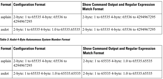
for autonomous system numbers, but you can configure 4-byte autonomous system numbers in both the asplain and asdot format. In addition, the default format for matching 4-byte autonomous system numbers in regular expressions is asplain, so you must ensure that any regular expressions to match 4-byte autonomous system numbers are written in the asplain format. If you want to change the defaultshowcommand output to display 4-byte autonomous system numbers in the asdot format, use thebgp asnotation dotcommand under router configuration mode. When the asdot format is enabled as the default, any regular expressions to match 4-byte autonomous system numbers must be written using the asdot format, or the regular expression match will fail. The tables below show that although you can configure 4-byte autonomous system numbers in either asplain or asdot format, only one format is used to displayshowcommand output and control 4-byte autonomous system number matching for regular expressions, and the default is asplain format. To display 4-byte autonomous system numbers inshowcommand output and to control matching for regular expressions in the asdot format, you must configure thebgp asnotation dotcommand. After enabling thebgp asnotation dot
command, a hard reset must be initiated for all BGP sessions by entering theclear ip bgp *command.
If you are upgrading to an image that supports 4-byte autonomous system numbers, you can still use 2-byte autonomous system numbers. Theshowcommand output and regular expression match are not changed and remain in asplain (decimal value) format for 2-byte autonomous system numbers regardless of the format configured for 4-byte autonomous system numbers.
Note
Table 2: Default Asplain 4-Byte Autonomous System Number Format
Show Command Output and Regular Expression Match Format Configuration Format Format 2-byte: 1 to 65535 4-byte: 65536 to 4294967295 2-byte: 1 to 65535 4-byte: 65536 to 4294967295 asplain 2-byte: 1 to 65535 4-byte: 65536 to 4294967295 2-byte: 1 to 65535 4-byte: 1.0 to 65535.65535 asdot
Table 3: Asdot 4-Byte Autonomous System Number Format
Show Command Output and Regular Expression Match Format Configuration Format Format 2-byte: 1 to 65535 4-byte: 1.0 to 65535.65535 2-byte: 1 to 65535 4-byte: 65536 to 4294967295 asplain 2-byte: 1 to 65535 4-byte: 1.0 to 65535.65535 2-byte: 1 to 65535 4-byte: 1.0 to 65535.65535 asdot
Reserved and Private Autonomous System Numbers
In Cisco IOS Release 12.0(32)S12, 12.0(32)SY8, 12.0(33)S3, 12.2(33)SRE, 12.2(33)XNE, 12.2(33)SXI1, 12.4(24)T, and later releases, the Cisco implementation of BGP supports RFC 4893. RFC 4893 was developed to allow BGP to support a gradual transition from 2-byte autonomous system numbers to 4-byte autonomous system numbers. A new reserved (private) autonomous system number, 23456, was created by RFC 4893 and this number cannot be configured as an autonomous system number in the Cisco IOS CLI.
RFC 5398,Autonomous System (AS) Number Reservation for Documentation Use, describes new reserved autonomous system numbers for documentation purposes. Use of the reserved numbers allow configuration examples to be accurately documented and avoids conflict with production networks if these configurations
Configuring a Basic BGP Network BGP Autonomous System Number Formats
are literally copied. The reserved numbers are documented in the IANA autonomous system number registry. Reserved 2-byte autonomous system numbers are in the contiguous block, 64496 to 64511 and reserved 4-byte autonomous system numbers are from 65536 to 65551 inclusive.
Private 2-byte autonomous system numbers are still valid in the range from 64512 to 65534 with 65535 being reserved for special use. Private autonomous system numbers can be used for internal routing domains but must be translated for traffic that is routed out to the Internet. BGP should not be configured to advertise private autonomous system numbers to external networks. Cisco IOS software does not remove private autonomous system numbers from routing updates by default. We recommend that ISPs filter private autonomous system numbers.
Autonomous system number assignment for public and private networks is governed by the IANA. For information about autonomous-system numbers, including reserved number assignment, or to apply to register an autonomous system number, see the following URL: http://www.iana.org/.
Note
Cisco Implementation of 4-Byte Autonomous System Numbers
In Cisco IOS Release 12.0(32)SY8, 12.0(33)S3, 12.2(33)SRE, 12.2(33)XNE, 12.2(33)SXI1, 15.1(1)SG, and later releases, the Cisco implementation of 4-byte autonomous system numbers uses asplain (65538, for example) as the default regular expression match and the output display format for AS numbers. However, you can configure 4-byte autonomous system numbers in both the asplain format and the asdot format as described in RFC 5396.
To change the default regular expression match and output display of 4-byte autonomous system numbers to asdot format, use thebgp asnotation dotcommand followed by theclear ip bgp *command to perform a hard reset of all current BGP sessions.
In Cisco IOS Release 12.0(32)S12, and 12.4(24)T, the Cisco implementation of 4-byte autonomous system numbers uses asdot (1.2, for example) as the only configuration format, regular expression match, and output display, with no asplain support.
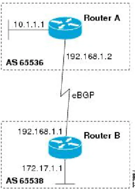
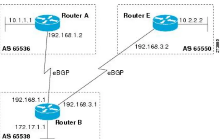
For an example of BGP peers in two autonomous systems using 4-byte numbers, see the figure below. To view a configuration example of the configuration between three neighbor peers in separate 4-byte autonomous systems configured using asdot notation, see the Examples: Configuring a BGP Routing Process and Peers Using 4-Byte Autonomous System Numbers.
Cisco also supports RFC 4893, which was developed to allow BGP to support a gradual transition from 2-byte autonomous system numbers to 4-byte autonomous system numbers. To ensure a smooth transition, we recommend that all BGP speakers within an autonomous system that is identified using a 4-byte autonomous system number be upgraded to support 4-byte autonomous system numbers.
A new private autonomous system number, 23456, was created by RFC 4893, and this number cannot be configured as an autonomous system number in the Cisco IOS CLI.
Note
Configuring a Basic BGP Network
Figure 1: BGP Peers in Two Autonomous Systems Using 4-Byte Numbers
BGP Peer Session Establishment
When a BGP routing process establishes a peering session with a peer, it goes through the following state changes:
• Idle—The initial state that the BGP routing process enters when the routing process is enabled or when the device is reset. In this state, the device waits for a start event, such as a peering configuration with a remote peer. After the device receives a TCP connection request from a remote peer, the device initiates another start event to wait for a timer before starting a TCP connection to a remote peer. If the device is reset, the peer is reset and the BGP routing process returns to the Idle state.
• Connect—The BGP routing process detects that a peer is trying to establish a TCP session with the local BGP speaker.
• Active—In this state, the BGP routing process tries to establish a TCP session with a peer device using the ConnectRetry timer. Start events are ignored while the BGP routing process is in the Active state. If the BGP routing process is reconfigured or if an error occurs, the BGP routing process will release system resources and return to an Idle state.
• OpenSent—The TCP connection is established, and the BGP routing process sends an OPEN message to the remote peer, and transitions to the OpenSent state. The BGP routing process can receive other OPEN messages in this state. If the connection fails, the BGP routing process transitions to the Active state.
• OpenReceive—The BGP routing process receives the OPEN message from the remote peer and waits for an initial keepalive message from the remote peer. When a keepalive message is received, the BGP routing process transitions to the Established state. If a notification message is received, the BGP routing process transitions to the Idle state. If an error or configuration change occurs that affects the peering session, the BGP routing process sends a notification message with the Finite State Machine (FSM) error code and then transitions to the Idle state.
• Established—The initial keepalive is received from the remote peer. Peering is now established with the remote neighbor and the BGP routing process starts exchanging update message with the remote peer.
Configuring a Basic BGP Network BGP Peer Session Establishment
The hold timer restarts when an update or keepalive message is received. If the BGP process receives an error notification, it will transition to the Idle state.
Cisco Implementation of BGP Global and Address Family Configuration
Commands
The address family model for configuring BGP is based on splitting apart the configuration for each address family. All commands that are independent of the address family are grouped together at the beginning (highest level) of the configuration, and these are followed by separate submodes for commands specific to each address family (with the exception that commands relating to IPv4 unicast can also be entered at the beginning of the configuration). When a network operator configures BGP, the flow of BGP configuration categories is represented by the following bullets in order:
• Global configuration—Configuration that is applied to BGP in general, rather than to specific neighbors. For example, thenetwork,redistribute, andbgp bestpathcommands.
• Address family-dependent configuration—Configuration that applies to a specific address family such as policy on an individual neighbor.
The relationship between BGP global and BGP address family-dependent configuration categories is shown in the table below.
Table 4: Relationships Between BGP Configuration Categories
Configuration Sets Within Category BGP Configuration Category
One set of global address family-independent configurations Global address family-independent
One set of global address family-dependent configurations per address family
Address family-dependent
Address family configuration must be entered within the address family submode to which it applies.
Note
The following is an example of BGP configuration statements showing the grouping of global address family-independent and address family-dependent commands.
router bgp <AS> ! AF independent part
neighbor <ip-address> <command> ! Session config; AF independent address-family ipv4 unicast
! AF dependant part
neighbor <ip-address> <command> ! Policy config; AF dependant exit-address-family
address-family ipv4 multicast ! AF dependant part
neighbor <ip-address> <command> ! Policy config; AF dependant exit-address-family
address-family ipv4 unicast vrf <vrf-name> ! VRF specific AS independent commands ! VRF specific AS dependant commands
neighbor <ip-address> <command> ! Session config; AF independent
Configuring a Basic BGP Network
neighbor <ip-address> <command> ! Policy config; AF dependant exit-address-family
The following example shows actual BGP commands that match the BGP configuration statements in the previous example: router bgp 45000 router-id 172.17.1.99 bgp log-neighbor-changes neighbor 192.168.1.2 remote-as 40000 neighbor 192.168.3.2 remote-as 50000 address-family ipv4 unicast
neighbor 192.168.1.2 activate
network 172.17.1.0 mask 255.255.255.0 exit-address-family
address-family ipv4 multicast neighbor 192.168.3.2 activate neighbor 192.168.3.2 advertisement-interval 25 network 172.16.1.0 mask 255.255.255.0 exit-address-family address-family ipv4 vrf vpn1 neighbor 192.168.3.2 activate network 172.21.1.0 mask 255.255.255.0 exit-address-family
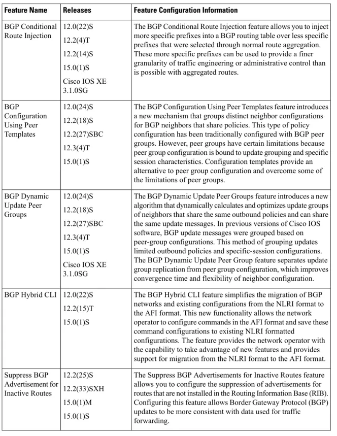
Thebgp upgrade-clicommand simplifies the migration of BGP networks and existing configurations from the network layer reachability information (NLRI) format to the address family format. Network operators can configure commands in the address family identifier (AFI) format and save these command configurations to existing NLRI formatted configurations. The BGP hybrid command-line interface (CLI) does not add support for complete AFI and NLRI integration because of the limitations of the NLRI format. For complete support of AFI commands and features, we recommend upgrading existing NLRI configurations with thebgp upgrade-clicommand. For an example of migrating BGP configurations from the NLRI format to the address family format, see the “Example: NLFI to AFI Configuration” section later in this module.
BGP Session Reset
Whenever the routing policy changes due to a configuration change, BGP peering sessions must be reset by using theclear ip bgpcommand. Cisco software supports the following three mechanisms to reset BGP peering sessions:
• Hard reset—A hard reset tears down the specified peering sessions including the TCP connection and deletes routes coming from the specified peer.
• Soft reset—A soft reset uses stored prefix information to reconfigure and activate BGP routing tables without tearing down existing peering sessions. Soft reconfiguration uses stored update information, at the cost of additional memory for storing the updates, to allow you to apply new BGP policy without disrupting the network. Soft reconfiguration can be configured for inbound or outbound sessions. • Dynamic inbound soft reset—The route refresh capability, as defined in RFC 2918, allows the local
device to reset inbound routing tables dynamically by exchanging route refresh requests to supporting peers. The route refresh capability does not store update information locally for nondisruptive policy changes. It instead relies on dynamic exchange with supporting peers. Route refresh must first be advertised through BGP capability negotiation between peers. All BGP devices must support the route refresh capability. To determine if a BGP device supports this capability, use theshow ip bgp neighbors
command. The following message is displayed in the output when the device supports the route refresh capability:
Configuring a Basic BGP Network BGP Session Reset
Received route refresh capability from peer.
Thebgp soft-reconfig-backupcommand was introduced to configure BGP to perform inbound soft reconfiguration for peers that do not support the route refresh capability. The configuration of this command allows you to configure BGP to store updates (soft reconfiguration) only as necessary. Peers that support the route refresh capability are unaffected by the configuration of this command.
BGP Route Aggregation
BGP peers store and exchange routing information and the amount of routing information increases as more BGP speakers are configured. The use of route aggregation reduces the amount of information involved. Aggregation is the process of combining the attributes of several different routes so that only a single route is advertised. Aggregate prefixes use the classless interdomain routing (CIDR) principle to combine contiguous networks into one classless set of IP addresses that can be summarized in routing tables. Fewer routes now need to be advertised.
Two methods are available in BGP to implement route aggregation. You can redistribute an aggregated route into BGP or you can use a form of conditional aggregation. Basic route redistribution involves creating an aggregate route and then redistributing the routes into BGP. Conditional aggregation involves creating an aggregate route and then advertising or suppressing the advertising of certain routes on the basis of route maps, autonomous system set path (AS-SET) information, or summary information.
Thebgp suppress-inactivecommand configures BGP to not advertise inactive routes to any BGP peer. A BGP routing process can advertise routes that are not installed in the routing information database (RIB) to BGP peers by default. A route that is not installed into the RIB is an inactive route. Inactive route advertisement can occur, for example, when routes are advertised through common route aggregation. Inactive route advertisements can be suppressed to provide more consistent data forwarding.
BGP Aggregation Route AS_SET Information Generation
AS_SET information can be generated when BGP routes are aggregated using theaggregate-addresscommand. The path advertised for such a route is an AS_SET consisting of all the elements, including the communities, contained in all the paths that are being summarized. If the AS_PATHs to be aggregated are identical, only the AS_PATH is advertised. The ATOMIC_AGGREGATE attribute, set by default for theaggregate-address
command, is not added to the AS_SET.
Routing Policy Change Management
Routing policies for a peer include all the configurations for elements such as route map, distribute list, prefix list, and filter list that may impact inbound or outbound routing table updates. The policy changes are automatically updated to peers whenever there is a change in the routing policy. Performing inbound reset enables the new inbound policy configured on the router to take effect. Performing outbound reset causes the new local outbound policy configured on the router to take effect without resetting the BGP session. As a new set of updates is sent during outbound policy reset, a new inbound policy of the neighbor can also take effect. This means that after changing inbound policy you must do an inbound reset on the local router or an outbound reset on the peer router. Outbound policy changes require an outbound reset on the local router or an inbound reset on the peer router.
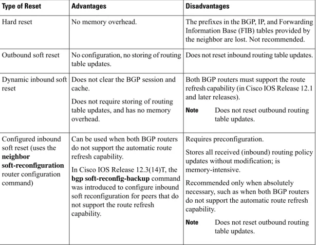
There are two types of reset: hard reset and soft reset. The table below lists their advantages and disadvantages.
Configuring a Basic BGP Network
Table 5: Advantages and Disadvantages of Hard and Soft Resets
Disadvantages Advantages
Type of Reset
The prefixes in the BGP, IP, and Forwarding Information Base (FIB) tables provided by the neighbor are lost. Not recommended. No memory overhead.
Hard reset
Does not reset inbound routing table updates. No configuration, no storing of routing
table updates. Outbound soft reset
Both BGP routers must support the route refresh capability (in Cisco IOS Release 12.1 and later releases).
Does not reset outbound routing table updates.
Note
Does not clear the BGP session and cache.
Does not require storing of routing table updates, and has no memory overhead.
Dynamic inbound soft reset
Requires preconfiguration.
Stores all received (inbound) routing policy updates without modification; is
memory-intensive.
Recommended only when absolutely necessary, such as when both BGP routers do not support the automatic route refresh capability.
Does not reset outbound routing table updates.
Note
Can be used when both BGP routers do not support the automatic route refresh capability.
In Cisco IOS Release 12.3(14)T, the
bgp soft-reconfig-backupcommand was introduced to configure inbound soft reconfiguration for peers that do not support the route refresh capability.
Configured inbound soft reset (uses the
neighbor
soft-reconfiguration
router configuration command)
Once you have defined two routers to be BGP neighbors, they will form a BGP connection and exchange routing information. If you subsequently change a BGP filter, weight, distance, version, or timer, or make a similar configuration change, you must reset BGP connections for the configuration change to take effect. A soft reset updates the routing table for inbound and outbound routing updates. Cisco IOS Release 12.1 and later releases support soft reset without any prior configuration. This soft reset allows the dynamic exchange of route refresh requests and routing information between BGP routers, and the subsequent readvertisement of the respective outbound routing table. There are two types of soft reset:
• When soft reset is used to generate inbound updates from a neighbor, it is called dynamic inbound soft reset.
• When soft reset is used to send a new set of updates to a neighbor, it is called outbound soft reset. To use soft reset without preconfiguration, both BGP peers must support the soft route refresh capability, which is advertised in the OPEN message sent when the peers establish a TCP session. Routers running Cisco IOS releases prior to Release 12.1 do not support the route refresh capability and must clear the BGP session using theneighbor soft-reconfigurationrouter configuration command. Clearing the BGP session in this way will have a negative impact upon network operations and should be used only as a last resort.
Configuring a Basic BGP Network Routing Policy Change Management
Conditional BGP Route Injection
Routes that are advertised through the BGP are commonly aggregated to minimize the number of routes that are used and reduce the size of global routing tables. However, common route aggregation can obscure more specific routing information that is more accurate but not necessary to forward packets to their destinations. Routing accuracy is obscured by common route aggregation because a prefix that represents multiple addresses or hosts over a large topological area cannot be accurately reflected in a single route. Cisco software provides several methods by which you can originate a prefix into BGP. Prior to the BGP conditional route injection feature, the existing methods included redistribution and using thenetworkoraggregate-addresscommand. However, these methods assume the existence of more specific routing information (matching the route to be originated) in either the routing table or the BGP table.
BGP conditional route injection allows you to originate a prefix into a BGP routing table without the corresponding match. This feature allows more specific routes to be generated based on administrative policy or traffic engineering information in order to provide more specific control over the forwarding of packets to these more specific routes, which are injected into the BGP routing table only if the configured conditions are met. Enabling this feature will allow you to improve the accuracy of common route aggregation by conditionally injecting or replacing less specific prefixes with more specific prefixes. Only prefixes that are equal to or more specific than the original prefix may be injected. BGP conditional route injection is enabled with thebgp inject-map exist-mapcommand and uses two route maps (inject map and exist map) to install one (or more) more specific prefixes into a BGP routing table. The exist map specifies the prefixes that the BGP speaker will track. The inject map defines the prefixes that will be created and installed into the local BGP table.
Inject maps and exist maps will only match a single prefix per route map clause. To inject additional prefixes, you must configure additional route map clauses. If multiple prefixes are used, the first prefix matched will be used.
Note
BGP Peer Groups
Often, in a BGP network, many neighbors are configured with the same update policies (that is, the same outbound route maps, distribute lists, filter lists, update source, and so on). Neighbors with the same update policies can be grouped into BGP peer groups to simplify configuration and, more importantly, to make configuration updates more efficient. When you have many peers, this approach is highly recommended.
BGP Backdoor Routes
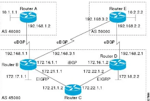
In a BGP network topology with two border devices using eBGP to communicate to a number of different autonomous systems, using eBGP to communicate between the two border devices may not be the most efficient routing method. In the figure below, Router B as a BGP speaker will receive a route to Router D through eBGP, but this route will traverse at least two autonomous systems. Router B and Router D are also connected through an Enhanced Interior Gateway Routing Protocol (EIGRP) network (any IGP can be used here), and this route has a shorter path. EIGRP routes, however, have a default administrative distance of 90, and eBGP routes have a default administrative distance of 20, so BGP will prefer the eBGP route. Changing the default administrative distances is not recommended because changing the administrative distance may lead to routing loops. To cause BGP to prefer the EIGRP route, you can use thenetwork backdoorcommand. BGP treats the network specified by thenetwork backdoorcommand as a locally assigned network, except
Configuring a Basic BGP Network
that it does not advertise the specified network in BGP updates. In the figure below, this means that Router B will communicate to Router D using the shorter EIGRP route instead of the longer eBGP route.
Figure 2: BGP Backdoor Route Topology
Peer Groups and BGP Update Messages
In Cisco IOS software releases prior to Release 12.0(24)S, 12.2(18)S, or 12.3(4)T, BGP update messages were grouped based on peer group configurations. This method of grouping neighbors for BGP update message generation reduced the amount of system processing resources needed to scan the routing table. This method, however, had the following limitations:
• All neighbors that shared peer group configuration also had to share outbound routing policies. • All neighbors had to belong to the same peer group and address family. Neighbors configured in different
address families could not belong to different peer groups.
These limitations existed to balance optimal update generation and replication against peer group configuration. These limitations could cause the network operator to configure smaller peer groups, which reduced the efficiency of update message generation and limited the scalability of neighbor configuration.
BGP Update Group
The introduction of the BGP (dynamic) update group provides a different type of BGP peer grouping from existing BGP peer groups. Existing peer groups are not affected but peers with the same outbound policy configured that are not members of a current peer group can be grouped into an update group. The members of this update group will use the same update generation engine. When BGP update groups are configured an algorithm dynamically calculates the BGP update group membership based on outbound policies. Optimal BGP update message generation occurs automatically and independently. BGP neighbor configuration is no longer restricted by outbound routing policies, and update groups can belong to different address families.
Configuring a Basic BGP Network Peer Groups and BGP Update Messages
BGP Dynamic Update Group Configuration
In Cisco IOS Release 12.0(24)S, 12.2(18)S, 12.3(4)T, 12.2(27)SBC, and later releases, a new algorithm was introduced that dynamically calculates and optimizes update groups of neighbors that share the same outbound policies and can share the same update messages. No configuration is required to enable the BGP dynamic update group and the algorithm runs automatically. When a change to outbound policy occurs, the router automatically recalculates update group memberships and applies the changes by triggering an outbound soft reset after a 1-minute timer expires. This behavior is designed to provide the network operator with time to change the configuration if a mistake is made. You can manually enable an outbound soft reset before the timer expires by entering theclear ip bgp ip-address soft outcommand.
In Cisco IOS Release 12.0(22)S, 12.2(14)S, 12.3(2)T, and prior releases, the update group recalculation delay timer is set to 3 minutes.
Note
For the best optimization of BGP update group generation, we recommend that the network operator keeps outbound routing policy the same for neighbors that have similar outbound policies.
BGP Peer Templates
To address some of the limitations of peer groups such as configuration management, BGP peer templates were introduced to support the BGP update group configuration.
A peer template is a configuration pattern that can be applied to neighbors that share policies. Peer templates are reusable and support inheritance, which allows the network operator to group and apply distinct neighbor configurations for BGP neighbors that share policies. Peer templates also allow the network operator to define very complex configuration patterns through the capability of a peer template to inherit a configuration from another peer template.
There are two types of peer templates:
• Peer session templates are used to group and apply the configuration of general session commands that are common to all address family and NLRI configuration modes.
• Peer policy templates are used to group and apply the configuration of commands that are applied within specific address families and NLRI configuration modes.
Peer templates improve the flexibility and enhance the capability of neighbor configuration. Peer templates also provide an alternative to peer group configuration and overcome some limitations of peer groups. BGP peer routers using peer templates also benefit from automatic update group configuration. With the configuration of the BGP peer templates and the support of the BGP dynamic update peer groups, the network operator no longer needs to configure peer groups in BGP and the network can benefit from improved configuration flexibility and faster convergence.
A BGP neighbor cannot be configured to work with both peer groups and peer templates. A BGP neighbor can be configured to belong only to a peer group or to inherit policies from peer templates.
Note
The following restrictions apply to the peer policy templates:
• A peer policy template can directly or indirectly inherit up to eight peer policy templates.
Configuring a Basic BGP Network
• A BGP neighbor cannot be configured to work with both peer groups and peer templates. A BGP neighbor can be configured to belong only to a peer group or to inherit policies only from peer templates.
Inheritance in Peer Templates
The inheritance capability is a key component of peer template operation. Inheritance in a peer template is similar to node and tree structures commonly found in general computing, for example, file and directory trees. A peer template can directly or indirectly inherit the configuration from another peer template. The directly inherited peer template represents the tree in the structure. The indirectly inherited peer template represents a node in the tree. Because each node also supports inheritance, branches can be created that apply the configurations of all indirectly inherited peer templates within a chain back to the directly inherited peer template or the source of the tree.
This structure eliminates the need to repeat configuration statements that are commonly reapplied to groups of neighbors because common configuration statements can be applied once and then indirectly inherited by peer templates that are applied to neighbor groups with common configurations. Configuration statements that are duplicated separately within a node and a tree are filtered out at the source of the tree by the directly inherited template. A directly inherited template will overwrite any indirectly inherited statements that are duplicated in the directly inherited template.
Inheritance expands the scalability and flexibility of neighbor configuration by allowing you to chain together peer templates configurations to create simple configurations that inherit common configuration statements or complex configurations that apply very specific configuration statements along with common inherited configurations. Specific details about configuring inheritance in peer session templates and peer policy templates are provided in the following sections.
When BGP neighbors use inherited peer templates it can be difficult to determine which policies are associated with a specific template. Thedetailkeyword was added to theshow ip bgp template peer-policycommand to display the detailed configuration of local and inherited policies associated with a specific template.
Peer Session Templates
Peer session templates are used to group and apply the configuration of general session commands to groups of neighbors that share session configuration elements. General session commands that are common for neighbors that are configured in different address families can be configured within the same peer session template. Peer session templates are created and configured in peer session configuration mode. Only general session commands can be configured in a peer session template. The following general session commands are supported by peer session templates:
•description •disable-connected-check •ebgp-multihop •exit peer-session •inherit peer-session •local-as •password •remote-as
Configuring a Basic BGP Network Inheritance in Peer Templates
•shutdown
•timers
•translate-update
•update-source
•version
General session commands can be configured once in a peer session template and then applied to many neighbors through the direct application of a peer session template or through indirect inheritance from a peer session template. The configuration of peer session templates simplifies the configuration of general session commands that are commonly applied to all neighbors within an autonomous system.
Peer session templates support direct and indirect inheritance. A peer can be configured with only one peer session template at a time, and that peer session template can contain only one indirectly inherited peer session template.
If you attempt to configure more than one inherit statement with a single peer session template, an error message will be displayed.
Note
This behavior allows a BGP neighbor to directly inherit only one session template and indirectly inherit up to seven additional peer session templates. This allows you to apply up to a maximum of eight peer session configurations to a neighbor: the configuration from the directly inherited peer session template and the configurations from up to seven indirectly inherited peer session templates. Inherited peer session configurations are evaluated first and applied starting with the last node in the branch and ending with the directly applied peer session template configuration at the source of the tree. The directly applied peer session template will have priority over inherited peer session template configurations. Any configuration statements that are duplicated in inherited peer session templates will be overwritten by the directly applied peer session template. So, if a general session command is reapplied with a different value, the subsequent value will have priority and overwrite the previous value that was configured in the indirectly inherited template. The following examples illustrate the use of this feature.
In the following example, the general session commandremote-as 1is applied in the peer session template named SESSION-TEMPLATE-ONE:
template peer-session SESSION-TEMPLATE-ONE remote-as 1
exit peer-session
Peer session templates support only general session commands. BGP policy configuration commands that are configured only for a specific address family or NLRI configuration mode are configured with peer policy templates.
Peer Policy Templates
Peer policy templates are used to group and apply the configuration of commands that are applied within specific address families and NLRI configuration mode. Peer policy templates are created and configured in peer policy configuration mode. BGP policy commands that are configured for specific address families are configured in a peer policy template. The following BGP policy commands are supported by peer policy templates:
Configuring a Basic BGP Network
•advertisement-interval •allowas-in •as-override •capability •default-originate •distribute-list •dmzlink-bw •exit-peer-policy •filter-list •inherit peer-policy •maximum-prefix •next-hop-self •next-hop-unchanged •prefix-list •remove-private-as •route-map •route-reflector-client •send-community •send-label •soft-reconfiguration •unsuppress-map •weight
Peer policy templates are used to configure BGP policy commands that are configured for neighbors that belong to specific address families. Like peer session templates, peer policy templates are configured once and then applied to many neighbors through the direct application of a peer policy template or through inheritance from peer policy templates. The configuration of peer policy templates simplifies the configuration of BGP policy commands that are applied to all neighbors within an autonomous system.
Like a peer session template, a peer policy template supports inheritance. However, there are minor differences. A directly applied peer policy template can directly or indirectly inherit configurations from up to seven peer policy templates. So, a total of eight peer policy templates can be applied to a neighbor or neighbor group. Like route maps, inherited peer policy templates are configured with sequence numbers. Also like a route map, an inherited peer policy template is evaluated starting with theinherit peer-policystatement with the lowest sequence number and ending with the highest sequence number. However, there is a difference; a peer policy template will not collapse like a route map. Every sequence is evaluated, and if a BGP policy command is reapplied with a different value, it will overwrite any previous value from a lower sequence number.
Configuring a Basic BGP Network Peer Policy Templates
The directly applied peer policy template and theinherit peer-policystatement with the highest sequence number will always have priority and be applied last. Commands that are reapplied in subsequent peer templates will always overwrite the previous values. This behavior is designed to allow you to apply common policy configurations to large neighbor groups and specific policy configurations only to certain neighbors and neighbor groups without duplicating individual policy configuration commands.
Peer policy templates support only policy configuration commands. BGP policy configuration commands that are configured only for specific address families are configured with peer policy templates.
The configuration of peer policy templates simplifies and improves the flexibility of BGP configuration. A specific policy can be configured once and referenced many times. Because a peer policy supports up to eight levels of inheritance, very specific and very complex BGP policies can also be created.
BGP IPv6 Neighbor Activation Under the IPv4 Address Family
Prior to Cisco IOS Release 12.2(33)SRE4, by default, both IPv6 and IPv4 capability is exchanged with a BGP peer that has an IPv6 address. When an IPv6 peer is configured, that neighbor is automatically activated under the IPv4 unicast address family.
Beginning with Cisco IOS Release 12.2(33)SRE4, when anewIPv6 neighbor is being configured, it is no longer automatically activated under the IPv4 address family. You can manually activate the IPv6 neighbor under the IPv4 address family if, for example, you have a dual stack environment and want to send IPv6 and IPv4 prefixes.
If you do not want anexistingIPv6 peer to be activated under the IPv4 address family, you can manually deactivate the peer with theno neighbor activatecommand. Until then, existing configurations that activate an IPv6 neighbor under the IPv4 unicast address family will continue to try to establish a session.
How to Configure a Basic BGP Network
Configuring a basic BGP network consists of a few required tasks and many optional tasks. A BGP routing process must be configured and BGP peers must be configured, preferably using the address family configuration model. If the BGP peers are part of a VPN network, the BGP peers must be configured using the IPv4 VRF address family task. The other tasks in the following list are optional:
Configuring a BGP Routing Process
Perform this task to configure a BGP routing process. You must perform the required steps at least once to enable BGP. The optional steps here allow you to configure additional features in your BGP network. Several of the features, such as logging neighbor resets and immediate reset of a peer when its link goes down, are enabled by default but are presented here to enhance your understanding of how your BGP network operates.
A device that runs Cisco software can be configured to run only one BGP routing process and to be a member of only one BGP autonomous system. However, a BGP routing process and autonomous system can support multiple concurrent BGP address family and subaddress family configurations.
Note
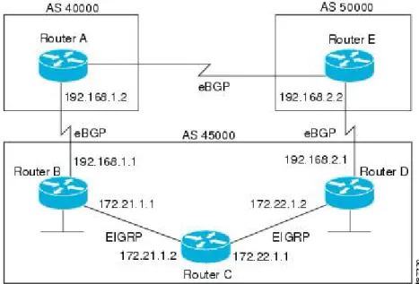
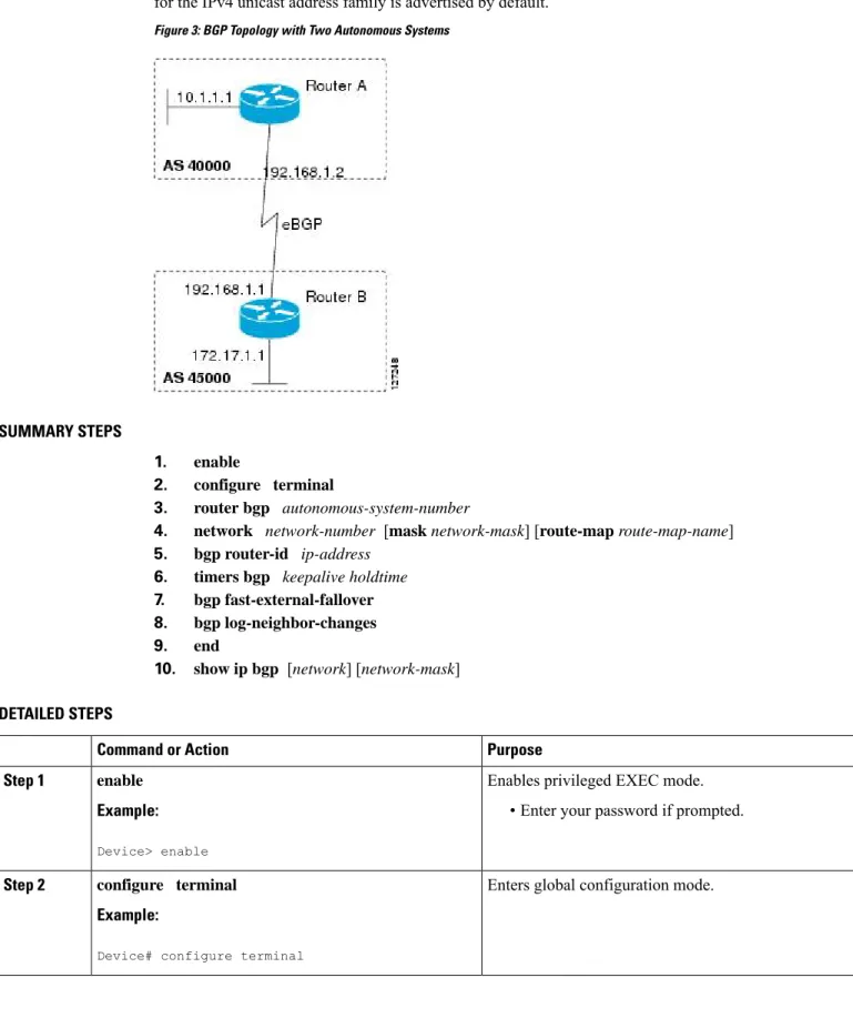
The configuration in this task is done at Router A in the figure below and would need to be repeated with appropriate changes to the IP addresses (for example, at Router B) to fully achieve a BGP process between
Configuring a Basic BGP Network
the two devices. No address family is configured here for the BGP routing process, so routing information for the IPv4 unicast address family is advertised by default.
Figure 3: BGP Topology with Two Autonomous Systems
SUMMARY STEPS
1. enable
2. configure terminal
3. router bgp autonomous-system-number
4. network network-number [mask network-mask] [route-map route-map-name] 5. bgp router-id ip-address
6. timers bgp keepalive holdtime 7. bgp fast-external-fallover 8. bgp log-neighbor-changes 9. end
10. show ip bgp [network] [network-mask]
DETAILED STEPS
Purpose Command or Action
Enables privileged EXEC mode.
enable Step 1
Example: • Enter your password if prompted.
Device> enable
Enters global configuration mode.
configure terminal Example:
Step 2
Device# configure terminal
Configuring a Basic BGP Network Configuring a BGP Routing Process
Purpose Command or Action
Configures a BGP routing process, and enters router configuration mode for the specified routing process.
router bgp autonomous-system-number Example:
Step 3
• Use theautonomous-system-numberargument to specify an integer, from 0 and 65534, that identifies the device to other BGP speakers.
Device(config)# router bgp 40000
(Optional) Specifies a network as local to this autonomous system and adds it to the BGP routing table.
network network-number [mask network-mask] [route-map route-map-name]
Step 4
Example: • For exterior protocols, thenetworkcommand controls
which networks are advertised. Interior protocols use
Device(config-router)# network 10.1.1.0 mask 255.255.255.0
thenetworkcommand to determine where to send updates.
(Optional) Configures a fixed 32-bit router ID as the identifier of the local device running BGP.
bgp router-id ip-address Example:
Step 5
• Use theip-addressargument to specify a unique router ID within the network.
Device(config-router)# bgp router-id 10.1.1.99
Configuring a router ID using thebgp router-id
command resets all active BGP peering sessions.
Note
(Optional) Sets BGP network timers.
timers bgp keepalive holdtime Step 6
Example: • Use thekeepaliveargument to specify the frequency,
in seconds, with which the software sends keepalive
Device(config-router)# timers bgp 70 120 messages to its BGP peer. By default, the keepalive
timer is set to 60 seconds.
• Use theholdtimeargument to specify the interval, in seconds, after which the software, having not received a keepalive message, declares a BGP peer dead. By default, the holdtime timer is set to 180 seconds. (Optional) Enables the automatic resetting of BGP sessions.
bgp fast-external-fallover Step 7
Example: • By default, the BGP sessions of any directly adjacent
external peers are reset if the link used to reach them goes down.
Device(config-router)# bgp fast-external-fallover
(Optional) Enables logging of BGP neighbor status changes (up or down) and neighbor resets.
bgp log-neighbor-changes Example:
Step 8
• Use this command for troubleshooting network connectivity problems and measuring network
Device(config-router)# bgp log-neighbor-changes
stability. Unexpected neighbor resets might indicate high error rates or high packet loss in the network and should be investigated.
Configuring a Basic BGP Network
Purpose Command or Action
Exits router configuration mode and enters privileged EXEC mode.
end Example: Step 9
Device(config-router)# end
(Optional) Displays the entries in the BGP routing table.
show ip bgp [network] [network-mask]
Step 10
Example: Only the syntax applicable to this task is used
in this example. For more details, see theCisco IOS IP Routing: BGP Command Reference.
Note
Device# show ip bgp
Examples
The following sample output from theshow ip bgpcommand shows the BGP routing table for Router A in the figure above after this task has been configured on Router A. You can see an entry for the network 10.1.1.0 that is local to this autonomous system.
BGP table version is 12, local router ID is 10.1.1.99
Status codes: s suppressed, d damped, h history, * valid, > best, i - internal, r RIB-failure, S Stale
Origin codes: i - IGP, e - EGP, ? - incomplete
Network Next Hop Metric LocPrf Weight Path *> 10.1.1.0/24 0.0.0.0 0 32768 i
Troubleshooting Tips
Use thepingcommand to check basic network connectivity between the BGP routers.
Configuring a BGP Peer
Perform this task to configure BGP between two IPv4 routers (peers). The address family configured here is the default IPv4 unicast address family and the configuration is done at Router A in the figure above. Remember to perform this task for any neighbor routers that are to be BGP peers.
Before you begin
Before you perform this task, perform the “Configuring a BGP Routing Process” task shown in the prior section.
By default, neighbors that are defined using theneighbor remote-ascommand in router configuration mode exchange only IPv4 unicast address prefixes. To exchange other address prefix types, such as IPv6 prefixes, neighbors must also be activated using theneighbor activatecommand in address family configuration mode for the other prefix types, such as IPv6 prefixes.
Note
Configuring a Basic BGP Network Troubleshooting Tips
SUMMARY STEPS
1. enable
2. configure terminal
3. router bgp autonomous-system-number
4. neighbor ip-address remote-as autonomous-system-number 5. address-family ipv4 [unicast|multicast|vrf vrf-name] 6. neighbor ip-address activate
7. end
8. show ip bgp [network] [network-mask] 9. show ip bgp neighbors [neighbor-address]
DETAILED STEPS
Purpose Command or Action
Enables privileged EXEC mode.
enable Step 1
Example: • Enter your password if prompted.
Router> enable
Enters global configuration mode.
configure terminal Example:
Step 2
Router# configure terminal
Enters router configuration mode for the specified routing process.
router bgp autonomous-system-number Example:
Step 3
Router(config)# router bgp 40000
Adds the IP address of the neighbor in the specified autonomous system to the IPv4 multiprotocol BGP neighbor table of the local router.
neighbor ip-address remote-as
autonomous-system-number
Example: Step 4
Router(config-router)# neighbor 192.168.1.1 remote-as 45000
Specifies the IPv4 address family and enters address family configuration mode.
address-family ipv4 [unicast|multicast|vrf vrf-name]
Example: Step 5
• Theunicastkeyword specifies the IPv4 unicast address family. By default, the router is placed in configuration
Router(config-router)# address-family ipv4 unicast
mode for the IPv4 unicast address family if theunicast
keyword is not specified with theaddress-family ipv4
command.
• Themulticastkeyword specifies IPv4 multicast address prefixes.
Configuring a Basic BGP Network
Purpose Command or Action
• Thevrfkeyword andvrf-nameargument specify the name of the virtual routing and forwarding (VRF) instance to associate with subsequent IPv4 address family configuration mode commands.
Enables the neighbor to exchange prefixes for the IPv4 unicast address family with the local router.
neighbor ip-address activate Example:
Step 6
Router(config-router-af)# neighbor 192.168.1.1 activate
Exits address family configuration mode and enters privileged EXEC mode.
end Example: Step 7
Router(config-router-af)# end
(Optional) Displays the entries in the BGP routing table.
show ip bgp [network] [network-mask]
Step 8
Example: Only the syntax applicable to this task is used in
this example. For more details, see theCisco IOS IP Routing: BGP Command Reference.
Note
Router# show ip bgp
(Optional) Displays information about the TCP and BGP connections to neighbors.
show ip bgp neighbors [neighbor-address]
Example: Step 9
Only the syntax applicable to this task is used in this example. For more details, see theCisco IOS IP Routing: BGP Command Reference.
Note
Router(config-router-af)# show ip bgp neighbors 192.168.2.2
Examples
The following sample output from theshow ip bgpcommand shows the BGP routing table for Router A in the figure above after this task has been configured on Router A and Router B. You can now see an entry for the network 172.17.1.0 in autonomous system 45000.
BGP table version is 13, local router ID is 10.1.1.99
Status codes: s suppressed, d damped, h history, * valid, > best, i - internal, r RIB-failure, S Stale
Origin codes: i - IGP, e - EGP, ? - incomplete
Network Next Hop Metric LocPrf Weight Path *> 10.1.1.0/24 0.0.0.0 0 32768 i *> 172.17.1.0/24 192.168.1.1 0 0 45000 i
The following sample output from theshow ip bgp neighborscommand shows information about the TCP and BGP connections to the BGP neighbor 192.168.1.1 of Router A in the figure above after this task has been configured on Router A:
BGP neighbor is 192.168.1.1, remote AS 45000, external link BGP version 4, remote router ID 172.17.1.99
BGP state = Established, up for 00:06:55
Configuring a Basic BGP Network Configuring a BGP Peer
Last read 00:00:15, last write 00:00:15, hold time is 120, keepalive intervals Configured hold time is 120,keepalive interval is 70 seconds, Minimum holdtims Neighbor capabilities:
Route refresh: advertised and received (old & new) Address family IPv4 Unicast: advertised and received Message statistics: InQ depth is 0 OutQ depth is 0 Sent Rcvd Opens: 1 1 Notifications: 0 0 Updates: 1 2 Keepalives: 13 13 Route Refresh: 0 0 Total: 15 16
Default minimum time between advertisement runs is 30 seconds For address family: IPv4 Unicast
BGP table version 13, neighbor version 13/0 Output queue size : 0
Index 1, Offset 0, Mask 0x2 1 update-group member
Sent Rcvd Prefix activity: ----
----Prefixes Current: 1 1 (Consumes 52 bytes) Prefixes Total: 1 1
Implicit Withdraw: 0 0 Explicit Withdraw: 0 0 Used as bestpath: n/a 1 Used as multipath: n/a 0
Outbound Inbound Local Policy Denied Prefixes: --- ---AS_PATH loop: n/a 1 Bestpath from this peer: 1 n/a
Total: 1 1
Number of NLRIs in the update sent: max 0, min 0 Connections established 1; dropped 0
Last reset never
Connection state is ESTAB, I/O status: 1, unread input bytes: 0 Connection is ECN Disabled
Local host: 192.168.1.2, Local port: 179 Foreign host: 192.168.1.1, Foreign port: 37725
Enqueued packets for retransmit: 0, input: 0 mis-ordered: 0 (0 bytes) Event Timers (current time is 0x12F4F2C):
Timer Starts Wakeups Next
Retrans 14 0 0x0 TimeWait 0 0 0x0 AckHold 13 8 0x0 SendWnd 0 0 0x0 KeepAlive 0 0 0x0 GiveUp 0 0 0x0 PmtuAger 0 0 0x0 DeadWait 0 0 0x0 iss: 165379618 snduna: 165379963 sndnxt: 165379963 sndwnd: 16040 irs: 3127821601 rcvnxt: 3127821993 rcvwnd: 15993 delrcvwnd: 391 SRTT: 254 ms, RTTO: 619 ms, RTV: 365 ms, KRTT: 0 ms
minRTT: 12 ms, maxRTT: 300 ms, ACK hold: 200 ms Flags: passive open, nagle, gen tcbs
IP Precedence value : 6
Datagrams (max data segment is 1460 bytes):
Rcvd: 20 (out of order: 0), with data: 15, total data bytes: 391
Sent: 22 (retransmit: 0, fastretransmit: 0, partialack: 0, Second Congestion: 04
Configuring a Basic BGP Network
Troubleshooting Tips
Use thepingcommand to verify basic network connectivity between the BGP routers.
What to Do Next
If you have BGP peers in a VPN, proceed to theConfiguring a BGP Peer for the IPv4 VRF Address Family, on page 30. If you do not have BGP peers in a VPN, proceed to theCustomizing a BGP Peer.
Configuring a BGP Routing Process and Peers Using 4-Byte Autonomous
System Numbers
Perform this task to configure a Border Gateway Protocol (BGP) routing process and BGP peers when the BGP peers are located in an autonomous system (AS) that uses 4-byte AS numbers. The address family configured here is the default IPv4 unicast address family, and the configuration is done at Router B in the figure above (in the “Cisco Implementation of 4-Byte Autonomous System Numbers” section). The 4-byte AS numbers in this task are formatted in the default asplain (decimal value) format; for example, Router B is in AS number 65538 in the figure above. Remember to perform this task for any neighbor routers that are to be BGP peers.
Before you begin
By default, neighbors that are defined using theneighbor remote-ascommand in router configuration mode exchange only IPv4 unicast address prefixes. To exchange other address prefix types, such as IPv6 prefixes, neighbors must also be activated using theneighbor activatecommand in address family configuration mode for the other prefix types.
Note
SUMMARY STEPS
1. enable
2. configure terminal
3. router bgp autonomous-system-number
4. neighbor ip-address remote-as autonomous-system-number 5. Repeat Step 4 to define other BGP neighbors, as required. 6. address-family ipv4 [unicast|multicast|vrf vrf-name] 7. neighbor ip-address activate
8. Repeat Step 7 to activate other BGP neighbors, as required.
9. network network-number [mask network-mask] [route-map route-map-name] 10. end
11. show ip bgp [network] [network-mask] 12. show ip bgp summary
DETAILED STEPS
Purpose Command or Action
Enables privileged EXEC mode.
enable Step 1
Configuring a Basic BGP Network Troubleshooting Tips
Purpose Command or Action
Example: • Enter your password if prompted.
Device> enable
Enters global configuration mode.
configure terminal Example:
Step 2
Device# configure terminal
Enters router configuration mode for the specified routing process.
router bgp autonomous-system-number Example:
Step 3
• In this example, the 4-byte AS number, 65538, is defined in asplain notation.
Device(config)# router bgp 65538
Adds the IP address of the neighbor in the specified AS to the IPv4 multiprotocol BGP neighbor table of the local device.
neighbor ip-address remote-as
autonomous-system-number
Example: Step 4
• In this example, the 4-byte AS number, 65536, is defined in asplain notation.
Device(config-router)# neighbor 192.168.1.2 remote-as 65536
--Repeat Step 4 to define other BGP neighbors, as required.
Step 5
Specifies the IPv4 address family and enters address family configuration mode.
address-family ipv4 [unicast|multicast|vrf vrf-name]
Example: Step 6
• Theunicastkeyword specifies the IPv4 unicast address family. By default, the device is placed in
Device(config-router)# address-family ipv4 unicast
configuration mode for the IPv4 unicast address family if theunicastkeyword is not specified with theaddress-family ipv4command.
• Themulticastkeyword specifies IPv4 multicast address prefixes.
• Thevrfkeyword andvrf-nameargument specify the name of the virtual routing and forwarding (VRF) instance to associate with subsequent IPv4 address family configuration mode commands.
Enables the neighbor to exchange prefixes for the IPv4 unicast address family with the local device.
neighbor ip-address activate Example:
Step 7
Device(config-router-af)# neighbor 192.168.1.2 activate
--Repeat Step 7 to activate other BGP neighbors, as required.
Step 8
(Optional) Specifies a network as local to this AS and adds it to the BGP routing table.
network network-number [mask network-mask] [route-map route-map-name]
Step 9
Configuring a Basic BGP Network
Purpose Command or Action
Example: • For exterior protocols thenetworkcommand controls
which networks are advertised. Interior protocols use
Device(config-router-af)# network 172.17.1.0 mask 255.255.255.0
thenetworkcommand to determine where to send updates.
Exits address family configuration mode and returns to privileged EXEC mode.
end Example: Step 10
Device(config-router-af)# end
(Optional) Displays the entries in the BGP routing table.
show ip bgp [network] [network-mask]
Step 11
Example: Only the syntax applicable to this task is used
in this example. For more details, see theCisco IOS IP Routing: BGP Command Reference.
Note
Device# show ip bgp 10.1.1.0
(Optional) Displays the status of all BGP connections.
show ip bgp summary Example:
Step 12
Device# show ip bgp summary
Examples
The following output from theshow ip bgpcommand at Router B shows the BGP routing table entry for network 10.1.1.0 learned from the BGP neighbor at 192.168.1.2 in Router A in the figure above with its 4-byte AS number of 65536 displayed in the default asplain format.
RouterB# show ip bgp 10.1.1.0
BGP routing table entry for 10.1.1.0/24, version 2 Paths: (1 available, best #1)
Advertised to update-groups: 2
65536
192.168.1.2 from 192.168.1.2 (10.1.1.99)
Origin IGP, metric 0, localpref 100, valid, external, best
The following output from theshow ip bgp summarycommand shows the 4-byte AS number 65536 for the BGP neighbor 192.168.1.2 of Router A in the figure above after this task has been configured on Router B:
RouterB# show ip bgp summary
BGP router identifier 172.17.1.99, local AS number 65538 BGP table version is 3, main routing table version 3 2 network entries using 234 bytes of memory
2 path entries using 104 bytes of memory
3/2 BGP path/bestpath attribute entries using 444 bytes of memory 1 BGP AS-PATH entries using 24 bytes of memory
0 BGP route-map cache entries using 0 bytes of memory 0 BGP filter-list cache entries using 0 bytes of memory BGP using 806 total bytes of memory
Configuring a Basic BGP Network Configuring a BGP Routing Process and Peers Using 4-Byte Autonomous System Numbers
BGP activity 2/0 prefixes, 2/0 paths, scan interval 60 secs
Neighbor V AS MsgRcvd MsgSent TblVer InQ OutQ Up/Down Stated 192.168.1.2 4 65536 6 6 3 0 0 00:01:33 1
Troubleshooting Tips
Use thepingcommand to verify basic network connectivity between the BGP routers.
Modifying the Default Output and Regular Expression Match Format for 4-Byte
Autonomous System Numbers
Perform this task to modify the default output format for 4-byte autonomous system (AS) numbers from asplain format to asdot notation format. Theshow ip bgp summarycommand is used to display the changes in output format for the 4-byte AS numbers.
SUMMARY STEPS 1. enable 2. show ip bgp summary 3. configure terminal 4. router bgp autonomous-system-number 5. bgp asnotation dot 6. end 7. clear ip bgp * 8. show ip bgp summary 9. show ip bgp regexp regexp 10. configure terminal 11. router bgp autonomous-system-number 12. no bgp asnotation dot 13. end 14. clear ip bgp * DETAILED STEPS Purpose Command or Action
Enables privileged EXEC mode.
enable Step 1
Example: • Enter your password if prompted.
Device> enable
Displays the status of all Border Gateway Protocol (BGP) connections.
show ip bgp summary Example:
Step 2
Device# show ip bgp summary
Enters global configuration mode.
configure terminal Example:
Step 3
Configuring a Basic BGP Network