Hagie 2100/2101/284/dts
Installation Manual
Spray Height Control System
Printed in Canada
Copyright 2005-08 by NORAC Systems International Inc.
Reorder P/N: UC4+BC+HG2-INST Rev I (Hagie 2100/2101/284/dts)
TABLE OF CONTENTS
1 INTRODUCTION ... 1
2 GENERAL SYSTEM DESCRIPTION ... 2
3 PARTS LISTS ... 3
4 INSTALLATION PROCEDURE ... 7
4.1 WING SENSOR INSTALLATION ... 7
4.2 MAIN LIFT SENSOR INSTALLATION ... 10
4.3 ROLL SENSOR INSTALLATION... 11
4.3.1 Boom Roll Sensor Mounting ... 12
4.3.2 Chassis Roll Sensor Mounting ... 13
4.3.3 Temperature Probe ... 13
4.4 HYDRAULIC INSTALLATION ... 14
4.4.1 Valve Mounting ... 14
4.4.2 Hydraulic Plumbing ... 15
4.5 ELECTRICAL INSTALLATION ... 16
4.6 COMPLETING THE INSTALLATION ... 18
5 ELECTRICAL REFERENCE – CABLE DRAWINGS ... 19
5.1 ITEM C01: 44662B-40–SENSOR TRUNK CABLE ... 19
5.2 ITEM C02:44668–SENSOR BRANCH CABLE ... 19
5.3 ITEM C02B: 44664–CABLE UC4CANNODE DUAL ... 20
5.4 ITEM C03:44656D–VALVE CABLE VARIABLE RATE DT ... 21
5.5 ITEM C04: 44651–VALVE EXTENSION CABLE ... 22
5.6 ITEM C06: 44687–CABLE UC3SENSOR AMPM TO AMPF ... 22
1
INTRODUCTION
Congratulations on your purchase of the NORAC UC4+ Spray Height Control System. This system is manufactured with top quality components and is engineered using the latest technology to provide operating features and reliability unmatched for years to come.
When properly used the system can provide protection from sprayer boom damage, improve sprayer efficiency, and ensure chemicals are applied correctly.
Please take the time to read this manual completely before attempting to install the system. A thorough understanding of this manual will ensure that you receive the maximum benefit from the system.
YOUR INPUT CAN HELP MAKE US BETTER! If you find issues or have suggestions regarding the parts list or the installation procedure, please don’t hesitate to contact us.
2
GENERAL SYSTEM DESCRIPTION
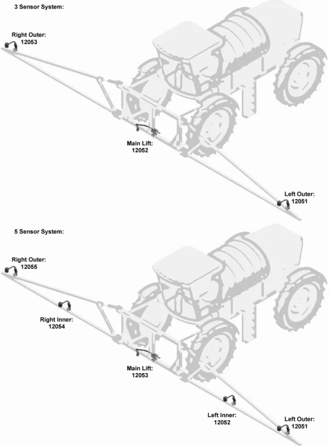
Figure 1 depicts the general system layout of the UC4+ Spray Height Control system. Some of your parts may look different and you may not have all the parts shown here.
Figure 1: System Components and General Location
NOTICE:
Every effort has been made to ensure the accuracy of the information contained in this manual. All parts supplied are selected specially to fit the sprayer to facilitate a complete installation. However, NORAC cannot guarantee all parts fit as intended due to the variations of the sprayer by the manufacturer. Please read this manual in its entirety before attempting installation.
ATTENTION:
When installing the UC4+ Spray Height Control system please be aware that at a point in the installation your sprayer booms will be inoperative until the installation is complete. Any installation procedure requiring boom movement will need to be done first. Once the hydraulics have been disconnected you must complete the electrical installation before the booms become operative.
3
PARTS LISTS
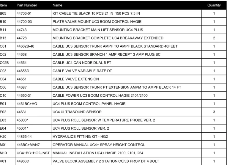
The parts that come with your UC4+ Spray Height Control System are listed in Table 1. The item number on the left side of this table references each part.
Please ensure that all parts in your kit are present before proceeding with your installation. Table 1: Hagie 2100/2101/284/dts Spray Height Control System Parts
Item Part Number Name Quantity
B05 44706-01 KIT CABLE TIE BLACK 10 PCS 21 IN 150 PCS 7.5 IN 1
B10 44700-03 PLATE VALVE MOUNT UC3 BOOM CONTROL HAGIE 1
B11 44743 MOUNTING BRACKET MAIN LIFT SENSOR UC4 PLUS 1
B13 44728 MOUNTING BRACKET COMPLETE UC4 BREAKAWAY EXTENDED 2
C01 44662B-40 CABLE UC3 SENSOR TRUNK AMPF TO AMPF BLACK STANDARD 40FEET 1 C02 44668 CABLE UC3 SENSOR BRANCH 1 AMP RECEPT 3 AMP PLUG BC 1
C02B 44664 CABLE UC4 CAN NODE DUAL 5 FT 1
C03 44656D CABLE VALVE VARIABLE RATE DT 1
C04 44651 CABLE VALVE EXTENSION 1
C06 44687 CABLE UC3 SENSOR TRUNK PT EXTENSION AMPM TO AMPF BLACK 14 FT 1
C10 44650-31 CABLE POWER UC3 BOOM CONTROL HAGIE 2101/2100 1
E01 4461BC+HG UC4 PLUS BOOM CONTROL PANEL HAGIE 1
E02 44631 UC4 ULTRASOUND SENSOR 3
E03 45000* UC4 PLUS ROLL SENSOR W TEMPERATURE PROBE VER. 2 1
E04 45001* UC4 PLUS ROLL SENSOR VER. 2 1
H20 44865-14 HYDRAULICS FITTING KIT - HG2 1
M01 446BC+MAN7 OPERATOR MANUAL UC4+ SPRAY HEIGHT CONTROL 1
M10 UC4+BC+HG2-INST MANUAL INSTALLATION UC4+ HAGIE 2100, 2101, 264 1 V01 44963D VALVE BLOCK ASSEMBLY 2 STATION CC/LS PROP DT 4 BOLT 1
* For systems purchased BEFORE October 1, 2011, the roll sensor part numbers are 44641 and 44642.
The use of dielectric grease is not recommended on any NORAC electrical connections. To ensure all stainless steel hardware does not gall or seize apply a light coating of the supplied Permatex Anti-seize grease to all threaded parts upon installation. Permatex Anti-seize lubricant is preferred, but other similar anti-seize products may be used.
Table 2: 44865-14 - Hydraulics Fittings Kit Details
Item Part Number Name Quantity Picture
F01 103195 6MJT 2
F02 104584 MALE TO FEMALE ADAPTER - 6MB 6FB 2
F03 103071 MALE 90 DEGREE ADAPTER - 8MB 6MJ90 2
F04 103814 MALE 90 DEGREE ADAPTER - 6MB 6MJ90 2
F05 103312 MALE ADAPTER - 6MB-6MJ 6
F06 44927 ORIFICE INSERT .031 IN ONE WAY 2
F08 44928 ORIFICE INSERT .047 IN ONE WAY 4
F09 104369 PLUG - 6MBP 4
F10 103839 TEE ADAPTER - 6FJXR 6MJT 2
NOTE: Not all fittings are used.
6 M B - 6 M OR X 90
SIZE IN 1/16TH'S GENDER: MALE OR FEMALE 90° ANGLE SWIVEL TYPE GENDER SIZE TYPE: B - ORB J - JIC OR - FLAT FACE P - PIPE Fitting Name Example:The parts that come with your UC4+ Spray Height Control system are shown below in their general installation configuration.
4
INSTALLATION PROCEDURE
4.1 WING SENSOR INSTALLATION
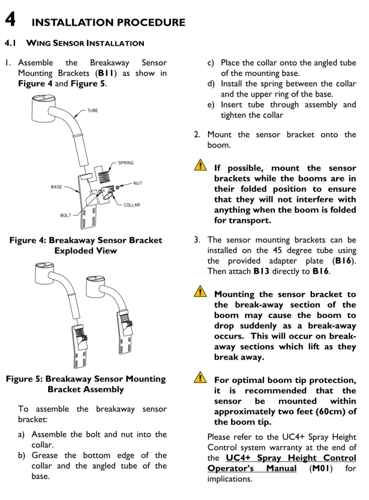
1. Assemble the Breakaway Sensor Mounting Brackets (B11) as show in
Figure 4 and Figure 5.
Figure 4: Breakaway Sensor Bracket Exploded View
Figure 5: Breakaway Sensor Mounting Bracket Assembly
To assemble the breakaway sensor bracket:
a) Assemble the bolt and nut into the collar.
b) Grease the bottom edge of the collar and the angled tube of the base.
c) Place the collar onto the angled tube of the mounting base.
d) Install the spring between the collar and the upper ring of the base.
e) Insert tube through assembly and tighten the collar
2. Mount the sensor bracket onto the boom.
If possible, mount the sensor brackets while the booms are in their folded position to ensure that they will not interfere with anything when the boom is folded for transport.
3. The sensor mounting brackets can be installed on the 45 degree tube using the provided adapter plate (B16). Then attach B13 directly to B16.
Mounting the sensor bracket to the break-away section of the boom may cause the boom to drop suddenly as a break-away occurs. This will occur on break-away sections which lift as they break away.
For optimal boom tip protection, it is recommended that the sensor be mounted within approximately two feet (60cm) of the boom tip.
Please refer to the UC4+ Spray Height Control system warranty at the end of the UC4+ Spray Height Control Operator’s Manual (M01) for implications.
4. Mount the NORAC UC4+ ultrasonic sensor (E02) into the sensor brackets. The sensors should be oriented forward (ahead) of the boom (see Figure 6 and
Figure 8).
When installing the UC4+ sensors (E02), start with the smallest serial number on the left hand side proceeding to the largest serial number on the right hand side (Figure 9).
5. Sensor cables should run through the mounting bracket tube and then behind the member the bracket is mounted onto. Cable-tie the connector in place. The cable must not be allowed to hang below the boom (Figure 6).
Figure 6: Another Acceptable Mounting
Avoid mounting sensors in locations where they may read from parts of the boom.
Figure 7: Poor Mounting (Sensor Reading off Boom)
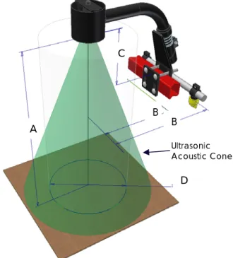
General mounting rules for UC4+ ultrasonic wing sensors:
a) In its lowest position, the sensor mouth
must be 9 inches or more from the ground.
b) The bottom of the sensor must be at
least 9 inches in front of the spray nozzles.
c) The bottom of the sensor must be at
least 9 inches above the spray nozzles.
d) Ensure that there are no obstructions
within a 12-inch diameter circle projected directly below the center of the sensor.
e) The sensor should be approximately
vertical at normal operating heights.
Figure 8: Sensor Mounting Guidelines
A B B D C Ultrasonic Acoustic Cone
Apply a light coating of the supplied Permatex Anti-seize grease to all threaded parts upon installation.
4.2 MAIN LIFT SENSOR INSTALLATION 1. Assemble the main lift sensor bracket
(B11) as shown in Figure 10.
Figure 10: Main Lift Sensor Bracket
2. The bracket should be mounted to the lowest frame member on the center section of the sprayer. The bracket should be mounted so the sensor mounting collar is approximately in the center of the sprayer.
Make sure the sensor has clearance when the main section is raised and lowered.
3. Mount the sensor onto the sensor mounting collar.
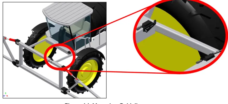
4. The final assembly is shown in Figure 11.
Figure 11: Main Lift Sensor Bracket Mounting Position
General mounting rules for ultrasonic main lift sensor:
a) Mount the sensor at the midpoint of the main lift section.
b) The sensor must have a 12-inch diameter clear view of the ground without any obstructions.
c) Ensure that there will be no contact between the sensor and the booms when folding and unfolding, or raising and lowering.
d) The bottom of the sensor must be at least 9 inches in front or behind the spray nozzles.
e) The bottom of the sensor must be at
least 9 inches above the spray nozzles.
Figure 12: An example of how to mount the main lift sensor on a front
mounted boom Bracket Tube Sensor Mounting Tab Sensor Mounting Collar Bracket Base
4.3 ROLL SENSOR INSTALLATION
Mount the roll sensors to the included roll sensor brackets using the machine screws and nylon lock nuts, as illustrated in Figure 13.
The roll sensors must be mounted tightly to the brackets.
Figure 13: Mounting the Roll Sensor to the Roll Sensor Mounting Bracket
When mounting the roll sensors use the following guidelines and refer to Figure 14.
1. Ensure the roll sensors are sitting relatively level when the sprayer chassis and boom are level.
2. Both roll sensors must be mounted with the circular AMP connector facing towards the Right-Hand Wing (when looking from the rear of the sprayer).
Figure 15: Roll Sensor Mounting with Respect to Sprayer Orientation
4.3.1 Boom Roll Sensor Mounting
The boom roll sensor is the roll sensor with the temperature probe attached to it (E03). To mount the boom roll sensor refer to these guidelines.
1. The boom roll sensor must be attached to the center part of the boom.
2. Use cable-ties to secure the bracket to a square edge feature (square tube).
3. The AMP (circular) connector must be pointing to the right hand wing (when looking from the rear).
4. The ring terminal on the boom roll sensor is a temperature probe and must be attached to the side of the valve block (Section 4.3.3).
Figure 16: Boom Roll Sensor Mounting Location
The roll sensors must be mounted with the Amp connectors pointing to the right.
4.3.2 Chassis Roll Sensor Mounting
The chassis roll sensor must be attached to the chassis of the sprayer. To mount the chassis roll sensor, refer to the following guidelines.
1. The chassis roll sensor does not have a temperature probe (E04).
2. Cable-tie the bracket to a square edge (square tube).
3. The AMP (circular) connector must exit towards the right hand wing (when looking from the rear).
Figure 17: Chassis Roll Sensor Mounting Location
4.3.3 Temperature Probe
Fasten the temperature probe (E03) to the UC4+ valve block using the included 3/8x1/2” bolt as illustrated in Figure 18.
Figure 18: UC4+ Valve Block with Temperature Probe Installed
4.4 HYDRAULIC INSTALLATION WARNING!
The hydraulic system creates very high pressure. Before disconnecting any hydraulic lines ensure all pressure has been bled from the system. When changing the boom hydraulic hoses leave the booms in TRANSPORT POSITION.
IMPORTANT:
Component failure due to oil contamination is not covered under the UC4+ Spray Height Control system warranty. It is recommended that a qualified technician does the hydraulic installation.
4.4.1 Valve Mounting
1. On a clean surface remove all plastic plugs from the NORAC hydraulic Valve (V01) (Figure 19).
Figure 19: NORAC Valve Block
2. Install the orifices (F08) into the "B" ports with the notch facing outward
as shown in Figure 20.
3. Install the orifices (F08) into the "A" ports with the notch facing inward
as shown in Figure 20.
4. Install the 6MB-6MJ fittings (F05) into the “A” and “B” ports and tighten to 18 ft-lbs.
5. Install 6MB-6MJ fittings (F05) into the “P” and “T” ports and tighten to 18 ft-lbs.
Figure 20: Valve Block Assembly
6. Remove the two bolts holding the Hagie valve block in place on the right side of the center rack. Bolt the supplied valve mounting plate (B10) in this location using the longer bolts (supplied with the bracket) (Figure 21).
4.4.2 Hydraulic Plumbing
WARNING!
From this point in the installation the booms will be inoperative until the electronics are fully installed.
After the NORAC valves are mounted, the hydraulic hoses and fittings can be plumbed. The plumbing for the hydraulic circuit is shown schematically in Figure 3.
The “B” lines of the NORAC valve block must be connected to the Hagie “raise” lines.
Ensure there are no other orifices present between the NORAC valve block and the boom cylinders.
You must ensure no hydraulic components will interfere with any sprayer parts or be pulled tight at any time.
4.5 ELECTRICAL INSTALLATION
1. Install the UC4+ Control Panel (E01) in the cab of the sprayer. Mount the panel where it will be clearly visible and within easy reach of the operator.
In the Hagie cab, a good spot to mount the UC4+ control panel is on the right hand side of the cab, next to the spray controller
Figure 22: Control Panel Mounting
2. Follow Figure 2 and Figure 24 to connect the UC4+ cabling.
Only connect the 3 pin shroud off C10 on sprayers with model number 2101.
3. Connect the 6 pin connector on C10 to the valve extension cable C04.
4. Route C04 and C01 to the front of the sprayer in the valve block vicinity.
5. Connect cable C02B to the free end of
C01.
6. Route one end of C02B to the boom frame roll sensors.
7. Connect cable C06 to the other free end of cable C02B and route cable
C06 to the chassis roll sensor, near the cab.
8. Connect the sensor branch cable (C02) to the free end of C02B. Route the other ends of the sensor branch cable to the three sensors.
Follow other hoses/cables along the booms and make sure they will not be stretched or pinched during boom movements.
9. Connect cable C03 to the valve extension cable (C04).
10. Connect the 2-pin connectors on C03
to the NORAC valve block.
11. The connectors on the valve cable (C03) are marked RIGHT UP, LEFT UP, RIGHT DOWN and LEFT DOWN. Cables labeled with UP go on the same side as the hydraulic hoses. 12. Cable-tie the installed cables every 12
inches.
IMPORTANT:
Provide enough slack in all cables to account for the movement of the main section, parallel lift, and FOLDING boom movement.
Figure 23: Valve Cable Connections
4.6 COMPLETING THE INSTALLATION 1. Start up your sprayer and test the
sprayer’s functionality. The NORAC Control Panel does not need to be powered up for the original switches to function. Unfold the booms and raise/lower each boom and main section.
Confirm that the cabling/hoses are agreeable to the entire range of motion.
2. If any functions do not work, review the hydraulic and electrical portions of this manual to check for proper installation. If you still have trouble, contact NORAC for assistance.
3. Turn on the power for the UC4+ Control Panel using the switch on the side of its chassis. .
4. The procedure for the installation of the UC4+ Spray Height Control system is now complete. Begin the AUTOMATIC SYSTEM SETUP procedure as described in the UC4+ Spray Height Control Operator’s Manual (M01).
5
ELECTRICAL REFERENCE – CABLE DRAWINGS
5.1 ITEM C01: 44662B-40–SENSOR TRUNK CABLE
5.5 ITEM C04: 44651–VALVE EXTENSION CABLE
Canada NORAC Systems International Inc.
CALL TOLL FREE: 1-800-667-3921 (306)664-6711 SHIPPING ADDRESS: 3702 Kinnear Place Saskatoon, SK S7P 0A6 United States NORAC, Inc.
CALL TOLL FREE: 1-866-306-6722 (952)224-4142 SHIPPING ADDRESS: 6667 West Old Shakopee Road, Suite 111 Bloomington, MN 55438
Europe NORAC Europe sarl
(+33) (0)4 26 47 04 42 SHIPPING ADDRESS: Rue de l’hermitage 01090 Guereins France