Zurich Open Repository and Archive University of Zurich Main Library Strickhofstrasse 39 CH-8057 Zurich www.zora.uzh.ch Year: 2016
Intensity modulated arc therapy implementation in a three phase adaptive
(18)F-FDG-PET voxel intensity-based planning strategy for head-and-neck
cancer
Berwouts, Dieter ; Olteanu, Luiza Ana Maria ; Speleers, Bruno ; Duprez, Frédéric ; Madani, Indira ; Vercauteren, Tom ; De Neve, Wilfried ; De Gersem, Werner
Abstract: BACKGROUND This study investigates the implementation of a new intensity modulated arc therapy (IMAT) class solution in comparison to a 6-static beam step-and-shoot intensity modulated radiotherapy (s-IMRT) for three-phase adaptive (18)F-FDG-PET-voxel-based dose-painting-by-numbers (DPBN) for head-and-neck cancer. METHODS We developed (18)F-FDG-PET-voxel intensity-based IMAT employing multiple arcs and compared it to clinically used s-IMRT DPBN. Three IMAT plans using (18)F-FDG-PET/CT acquired before treatment (phase I), after 8 fractions (phase II) and CT acquired after 18 fractions (phase III) were generated for each of 10 patients treated with 3 s-IMRT plans based on the same image sets. Based on deformable image registration (ABAS, version 0.41, Elekta CMS Software, Maryland Heights, MO), doses of the 3 plans were summed on the pretreatment CT using validated in-house developed software. Dosimetric indices in targets and organs-at-risk (OARs), biologic conformity of treatment plans set at �5 %, treatment quality and efficiency were compared between IMAT and s-IMRT for the whole group and for individual patients. RESULTS Doses to most organs-at-risk (OARs) were significantly better in IMAT plans, while target levels were similar for both types of plans. On average, IMAT ipsilateral and contralateral parotid mean doses were 14.0 % (p = 0.001) and 12.7 % (p < 0.001) lower, respectively. Pharyngeal constrictors D50% levels were similar or reduced with up to 54.9 % for IMAT compared to s-IMRT for individual patient cases. IMAT significantly improved biologic conformity by 2.1 % for treatment phases I and II. 3D phantom measurements reported an agreement of �95 % for 3 % and 3 mm criteria for both treatment modalities. IMAT delivery time was significantly shortened on average by 41.1 %. CONCLUSIONS IMAT implementation significantly improved the biologic conformity as compared to s-IMRT in adaptive dose-escalated DPBN treatments. The better OAR sparing and faster delivery highly improved the treatment efficiency.
DOI: https://doi.org/10.1186/s13014-016-0629-3
Posted at the Zurich Open Repository and Archive, University of Zurich ZORA URL: https://doi.org/10.5167/uzh-130486
Journal Article Published Version
The following work is licensed under a Creative Commons: Attribution 4.0 International (CC BY 4.0) License.
Originally published at:
Berwouts, Dieter; Olteanu, Luiza Ana Maria; Speleers, Bruno; Duprez, Frédéric; Madani, Indira; Ver-cauteren, Tom; De Neve, Wilfried; De Gersem, Werner (2016). Intensity modulated arc therapy im-plementation in a three phase adaptive (18)F-FDG-PET voxel intensity-based planning strategy for head-and-neck cancer. Radiation Oncology, 11:52.
DOI: https://doi.org/10.1186/s13014-016-0629-3
R E S E A R C H
Open Access
Intensity modulated arc therapy
implementation in a three phase adaptive
18
F-FDG-PET voxel intensity-based planning
strategy for head-and-neck cancer
Dieter Berwouts
1,2*†, Luiza Ana Maria Olteanu
1†, Bruno Speleers
3, Frédéric Duprez
1, Indira Madani
3,4,
Tom Vercauteren
1, Wilfried De Neve
1,3and Werner De Gersem
3Abstract
Background:This study investigates the implementation of a new intensity modulated arc therapy (IMAT) class solution in comparison to a 6-static beam step-and-shoot intensity modulated radiotherapy (s-IMRT) for three-phase adaptive
18
F-FDG-PET-voxel-based dose-painting-by-numbers (DPBN) for head-and-neck cancer.
Methods:We developed18F-FDG-PET-voxel intensity-based IMAT employing multiple arcs and compared it to clinically used s-IMRT DPBN. Three IMAT plans using18F-FDG-PET/CT acquired before treatment (phase I), after 8 fractions (phase II) and CT acquired after 18 fractions (phase III) were generated for each of 10 patients treated with 3 s-IMRT plans based on the same image sets. Based on deformable image registration (ABAS, version 0.41, Elekta CMS Software, Maryland Heights, MO), doses of the 3 plans were summed on the pretreatment CT using validated in-house developed software. Dosimetric indices in targets and organs-at-risk (OARs), biologic conformity of treatment plans set at≤5 %, treatment quality and efficiency were compared between IMAT and s-IMRT for the whole group and for individual patients.
Results:Doses to most organs-at-risk (OARs) were significantly better in IMAT plans, while target levels were similar for both types of plans. On average, IMAT ipsilateral and contralateral parotid mean doses were 14.0 % (p= 0.001) and 12.7 % (p< 0.001) lower, respectively. Pharyngeal constrictors D50%levels were similar or reduced with up to 54.9 % for IMAT
compared to s-IMRT for individual patient cases. IMAT significantly improved biologic conformity by 2.1 % for treatment phases I and II. 3D phantom measurements reported an agreement of≥95 % for 3 % and 3 mm criteria for both treatment modalities. IMAT delivery time was significantly shortened on average by 41.1 %.
Conclusions:IMAT implementation significantly improved the biologic conformity as compared to s-IMRT in adaptive dose-escalated DPBN treatments. The better OAR sparing and faster delivery highly improved the treatment efficiency.
Keywords:Adaptive intensity modulated arc therapy, Dose-painting, Intensity modulated radiotherapy, Head-and-neck cancer
* Correspondence:[email protected] †Equal contributors
1Department of Radiotherapy, Ghent University Hospital, De Pintelaan 185,
9000 Ghent, Belgium
2Department of Nuclear Medicine, Ghent University Hospital, Ghent, Belgium
Full list of author information is available at the end of the article
© 2016 Berwouts et al.Open AccessThis article is distributed under the terms of the Creative Commons Attribution 4.0 International License (http://creativecommons.org/licenses/by/4.0/), which permits unrestricted use, distribution, and reproduction in any medium, provided you give appropriate credit to the original author(s) and the source, provide a link to the Creative Commons license, and indicate if changes were made. The Creative Commons Public Domain Dedication waiver (http://creativecommons.org/publicdomain/zero/1.0/) applies to the data made available in this article, unless otherwise stated.
Berwoutset al. Radiation Oncology (2016) 11:52
Background
Intensity-modulated radiation therapy (IMRT) has become a standard treatment of head-and-neck cancer due to its ability to decrease radiation-induced toxicity [1–3], though the survival rates have not been significantly improved. Since its introduction, different delivery techniques have evolved to make IMRT faster, more precise and flexible. At present, static, dynamic and rotational IMRT are in use demonstrating comparable dose coverage and conformity [4, 5]. Because of a faster delivery, rotational techniques like intensity-modulated arc therapy (IMAT) gained wide-spread use over recent years. A comparison of different ro-tational techniques has already been done in literature and it is beyond the scope of this paper [6]. Commercial solu-tions to perform IMAT are currently available for as well Elekta (Crawley, UK) as Varian (Palo Alto, CA, USA).
In planning studies for head-and-neck cancer, IMAT demonstrated better sparing of organs-at-risk (OARs) with-out increasing integral dose when compared to static or dynamic IMRT [4–6]. IMAT has the ability to modulate intensities at an infinite number of gantry angles resulting in superior, highly structured dose distributions that are needed for dose painting, i.e., mapping dose to tumor het-erogeneity detected by biologic imaging. Up to now, clinical dose-painting by numbers for head-and-neck cancer was based on non-rotational IMRT [7, 8]. The potential of bio-logical image-based IMAT has not been explored yet. We developed an 18F-FDG-PET-voxel intensity-based IMAT class solution and investigated its possible implementation in comparison to clinically used adaptive step-and-shoot
18
F-FDG-PET-voxel intensity-based IMRT (s-IMRT). Here-with we present the results of our study.
Methods Study population
The first 10 head-and-neck cancer patients treated with
adaptive 18F-FDG-PET-voxel intensity-based IMRT in
a randomized phase II dose-escalation clinical trial (NCT01341535) were selected for this study (Table 1).
All tumors were biopsy-proven non-metastatic head-and-neck squamous cell carcinomas.
Imaging and target definition
All patients were positioned with a five-point thermoplas-tic mask (Orfit Industries N.V., Belgium), which extended down to the shoulders, during computed-tomography (CT) isocenter simulation and treatment delivery. Planning CT scans of 3 mm slice thickness were acquired before the treatment and after the 8thand 18thfraction. A verification CT was taken at the treatment end. Contrast-enhanced
18
F-FDG-PET/CT (Philips Medical Systems, Germany) was performed before treatment and after the 8th frac-tion. 18F-FDG-PET-images were acquired with a voxel size of 4 x 4 x 4 mm3as described earlier [9]. Fusion of
the planning CT and18F-FDG-PET/CT scans was done
on a Pinnacle treatment planning system, version 9.0 (Philips Medical Systems, Andover, MA).
Delineation of the gross tumor volume of the primary tumor (GTVT) and pathological lymph nodes (GTVN)
was done using mutual information of both anatomical and biological imaging. A threshold level of 50 % of
SUVMAX (maximal standardised uptake value) was set
for 18F-FDG-uptake in Pinnacle. Pathologic lymph nodes were delineated separately and noted as the GTVN1 and
GTVN2. The high-risk clinical target volume (CTVHR) was
created combining the GTVN and a three-dimensional
expansion of the GTVT with 1 cm and adjusted to the air
cavities and uninvolved bones. 3 mm margin to the CTVHR
was used to create the high risk planning target volume (PTVHR). Delineation of the elective neck regions according
to the guidelines of Gregoire et al. [10] resulted in the CTV of the elective neck (CTVEN) and the elective neck PTV
(PTVEN) after a 3 mm expansion in all directions.
The considered organs-at-risk (OARs) were spinal cord, brainstem, swallowing structures defined as one region-of-interest (superior, medial and inferior pharyngeal con-strictor, upper oesophageal sphincter, first 2 cm of the oesophagus and supraglottic larynx), parotids and man-dible. Planning OAR volumes (PRVs) were created for the spinal cord and brainstem by three-dimensional expan-sions of 5 mm and 3 mm, respectively.
Deformable image co-registration (ABAS, version 0.41, Elekta CMS Software, Maryland Heights, MO) was used to propagate the targets and OAR contours from one CT to another in chronological order. All structures were reviewed and edited if necessary by an experienced head-and-neck radiation oncologist.
Dose prescription and treatment planning
Treatment phases I, II and III consisted of 10 fractions planned on the 1st, 2nd and 3rd CT set, respectively.
Dose-painting was performed in GTVTand GTVN
dur-ing the first 20 fractions. The dose range was between Table 1Patient characteristics
Patient No. Age (years) Tumor site Tumor subsite TN-stage
1 64 Oropharynx Tonsil cT4a pN2b
2 48 Oropharynx Base of Tongue cT1 cN2c
3 54 Oropharynx Tonsil cT4a cN2c
4 74 Hypopharynx Aryepiglottic Fold cT2 cN1
5 40 Hypopharynx Piriform Sinus cT1 pN2a
6 53 Larynx Glottis cT3 cN0
7 52 Oropharynx Vallecula cT1 pN2b
8 54 Oropharynx Tonsil cT2 cN2c
9 59 Larynx Supraglottis cT2 cN0
10 58 Oropharynx Vallecula cT4a cN2c
2.2 Gy and 3.1 Gy per fraction in phases I and II. Only a GTVT volume≤1.75 cm3 was allowed to receive more
than 2.9 Gy per fraction. GTVN was dose-painted in 4
out of 6 patients with N+ disease; in the 2 other patients, which had a pathological lymph node volume≤4 cm3, the GTVNmedian prescription dose was 2.2 Gy per
frac-tion. The total dose range for the GTVTand GTVNwas
66-83 Gy.
No dose-painting was performed during the last 10 fractions, where a D95% of 2.0 Gy/fx was prescribed to
PTVHR. Elective neck was irradiated during fractions
1-20 with a median total dose prescription of 40 Gy to PTVEN. GTVTand GTVN biologic conformity was
mea-sured by a quality factor (QF), defined as the mean devi-ation between prescribed and planned dose in each PET/CT voxel [9]. QF was kept below 5 % where pos-sible. Every treatment was planned to a total of 30 frac-tions and then rescaled to 10 fracfrac-tions. Maximum doses of 50, 60 and 70 Gy were allowed to < 5 % of the spinal cord (PRV), brainstem (PRV) and mandible, respectively. A maximal dose of less than 45 Gy for the spinal cord, 50 Gy for the brainstem and 27 Gy to < 50 % of the vol-ume of the spared parotids, respectively, were consid-ered clinically acceptable.
The methodology of 18F-FDG-PET voxel
intensity-based DPBN has been previously discussed [9]. Briefly, a dose is prescribed to the voxels in the dose-painted tar-get volume as a function of signal intensity as follows:
D Ið Þ ¼ Dlow I ≤Ilow
D Ið Þ ¼ DlowþII−Ilow
high−Ilow Dhigh−Dlow
Ilow≤I≤Ihigh
D Ið Þ ¼ Dhigh Ihigh≤I
where the signal intensities Ihighand Iloware determined
as 95 % of the maximum 18F-FDG-PET intensity and as 25 % of Ihigh, respectively. The extension of the discrete
PET intensity data to the continuum was implemented using trilinear interpolation for the randomly seeded points in the delineated volumes. Using the PET-intensity to dose relation, the dose prescription was on a point-by-point base.
All treatment plans were created for an Elekta linac (Crawley, UK) equipped with a standard multileaf colli-mator with 40 leaf pairs, capable of delivering s-IMRT and IMAT with variable dose rate, gantry and collimator rotation speed. In-house developed software using an anatomy- and 18F-FDG-PET-voxel intensity-based seg-mentation tool (ABST, BBST) followed by leaf position and monitor unit (MU) optimization was used for treat-ment planning [11, 12].
s-IMRT plans consisted of six non-opposing coplanar 6 MV beams with gantry angles of 45°, 75°, 165°, 195°,
285° and 315°. The IMAT class solution was made of 6
MV arcs collimated around PTVEN (gantry angle from
-176° to 176°) and PTVHR (144° to -144°) with control
points (CPs) defined every 8°. The only constraints were on the physical abilities of the linear accelerator to de-liver the treatment (maximum gantry speed, maximum collimator rotation speed, maximum leaf speed, mini-mum dose rate), and a minimini-mum distance constraint of 1 cm for opposite and diagonally-opposite leaves of the MLC. ABST [11] was used to create the starting set of CPs, resulting in multiple initial arcs, avoiding both pa-rotids, the swallowing structures and the PRV of the spinal cord. The CPs were optimized as described previ-ously [12]. ABST generates beam segments with leaf and jaw positions based on a beams-eye-view projection of selected PTVs and OARs. BBST additionally takes into account PET-intensities to create initial beam segments shapes [9]. For a faster delivery, the parts of the arcs with a contribution of less than 2 MUs were eliminated during the optimization leading to the split of the arcs in sub-arcs. A CP refinement was performed by interpolating and generating additional CPs within the arcs, followed by MU and leaf position optimization. This CP refinement limited MU differences, gantry and collimator angle differ-ences, leaf and jaw position movements between CPs and was applied to reach the accuracy constraints used in the treatment verification. After the final optimization, the remaining arcs were linked together in one beam accord-ing to the shortest possible delivery time. All dose compu-tations were done in Pinnacle with a collapsed cone convolution/superposition calculation algorithm.
Dose reporting and statistical analysis
Doses of the 3 treatment plans were summed on the pre-treatment CT using in-house developed software [13] based on the deformable CT image registrations made with the ABAS software. The reporting of the region-of-interest (ROI) dose levels was done on the summed doses. To assess the risk of inducing secondary malignancies, the integral dose was calculated in the patient volume as follows:
ID ¼ Dmean⋅V⋅ρ
where Dmean is the mean dose, V is the volume and ρ
the tissue density, which was considered to be 1 g/cm3. Statistical tests of dosimetric, biologic conformity, treat-ment verification and quality (MUs and delivery time) dif-ferences between s-IMRT and IMAT were done using a two-sided Wilcoxon matched-pair signed rank test with SPSS software version 20.0 (SPSS Inc., Chicago, IL). Differences were considered statistically significant for p-values <0.05.
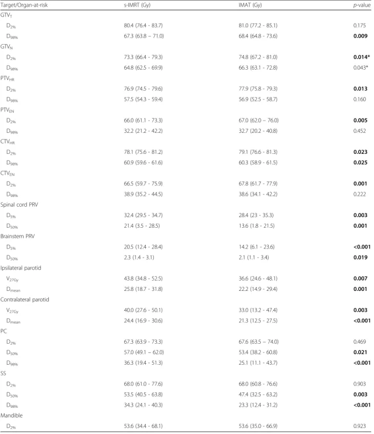
Table 2Population average dose levels for s-IMRT and IMAT treatments
Target/Organ-at-risk s-IMRT (Gy) IMAT (Gy) p-value
GTVT D2% 80.4 (76.4 - 83.7) 81.0 (77.2 - 85.1) 0.175 D98% 67.3 (63.8–71.0) 68.4 (64.8 - 73.6) 0.009 GTVN D2% 73.3 (66.4 - 79.3) 74.8 (67.2 - 81.0) 0.014* D98% 64.8 (62.5 - 69.9) 66.3 (63.1 - 72.8) 0.043* PTVHR D2% 76.9 (74.5 - 79.6) 77.9 (75.8 - 79.3) 0.013 D98% 57.5 (54.3 - 59.4) 56.9 (52.5 - 58.7) 0.160 PTVEN D2% 66.0 (61.1 - 73.3) 67.0 (62.0–76.0) 0.005 D98% 32.2 (21.2 - 42.2) 32.7 (20.2 - 40.8) 0.452 CTVHR D2% 78.1 (75.6 - 81.2) 79.1 (76.6 - 81.3) 0.023 D98% 60.9 (59.6 - 61.6) 60.3 (58.9 - 61.5) 0.025 CTVEN D2% 66.5 (59.7 - 75.9) 67.8 (61.7 - 77.9) 0.001 D98% 38.9 (35.2 - 44.5) 38.6 (34.1 - 42.2) 0.222 Spinal cord PRV D5% 32.4 (29.5 - 34.7) 28.4 (23 - 35.3) 0.003 D50% 21.4 (3.5 - 28.5) 13.6 (1.8 - 21.5) 0.001 Brainstem PRV D5% 20.5 (12.4 - 28.4) 14.2 (6.1 - 23.6) <0.001 D50% 2.3 (1.4 - 3.1) 2.1 (1.1 - 3.4) 0.019 Ipsilateral parotid V27Gy 43.8 (34.8 - 52.5) 36.6 (24.6 - 48.1) 0.007 Dmean 25.8 (18.7 - 31.8) 22.2 (14.9 - 29.4) 0.001 Contralateral parotid V27Gy 40.0 (27.6 - 50.1) 33.0 (13.2 - 47.4) 0.003 Dmean 24.4 (16.9 - 30.6) 21.3 (12.5 - 27.5) <0.001 PC D2% 67.3 (63.9 - 73.3) 67.6 (63.5–74.0) 0.469 D50% 57.0 (49.1–62.0) 53.4 (38.2 - 60.8) 0.021 D98% 36.3 (19.4 - 51.3) 25.1 (11.1 - 43.7) <0.001 SS D2% 68.0 (61.0 - 77.6) 68.0 (60.8 - 76.6) 0.903 D50% 53.5 (40.5 - 63.8) 47.4 (32.5 - 63.2) 0.003 D98% 34.3 (24.1 - 40.3) 23.3 (12.4 - 31.2) <0.001 Mandible D2% 53.6 (34.4 - 68.1) 53.6 (35.0 - 66.9) 0.923
The dose distributions of the 3 treatment phases were summed on the pretreatment CT. Reporting is done on manually delineated targets and organs-at-risk. Statistically significant differences are shown in bold
Abbreviations:s-IMRTstep-and-shoot IMRT,IMATintensity modulated arc therapy,GTVTgross tumor volume of the primary tumor,GTVNGTV of the metastatic
lymph nodes,CTVHRhigh-risk clinical target volume,PTVHRhigh-risk planning target volume,CTVENelective neck CTV,PTVENelective neck PTV,PRVplanning
organ-at-risk volume,SSswallowing structures include the superior, middle and inferior pharyngeal constrictor muscles, upper esophageal sphincter, supraglottic larynx and upper 2 cm of the cervical esophagus,PCpharyngeal constrictors include the superior, middle and inferior pharyngeal constrictor muscles,Dx%dose
received by x% of the volume,V27Gy% of the volume that receives at least 27 Gy
*Of 10 patients, 6 had metastatic lymph nodes
Treatment verification
The delivered dose distributions of all IMAT and s-IMRT treatment plans were verified with the 3D dosimetry system Delta4(Scandidos, Uppsala, Sweden). The Delta4phantom has 1069 p-type disc-shaped Silicon diodes with a diameter of 1 mm and axial size 0.05 mm, in a central region (6x6 cm) spaced per 5 mm, outside the central region spaced per 10 mm. Global gamma indices [14] were deter-mined in the Delta4control software for the criteria of 3 % dose difference and 3 mm distance-to-agreement, the normalization dose being the prescribed dose.
The delivery treatment time was also recorded from the start of the first beam till the end of the last beam. Results
Dosimetrical and biological conformity results
Population average dose-volume parameters of targets and OARs for both strategies are shown in Table 2. Most of the differences between s-IMRT and IMAT for target and OAR dose levels were significant (Table 2). Mean V27Gy of ipsi- and contralateral parotids were improved
by 16.4 % (p= 0.007) and 17.5 % (p= 0.003) in the IMAT plans, respectively. For the volume of interest that com-prised the pharyngeal constrictor muscles (PC) and the one that combined the swallowing structures (SS), both D50%and D98%levels were significantly improved in the
IMAT plans, while D2%did not show on average any
im-portant differences.
Analysis of each summed dose distribution separately revealed larger differences for some cases in comparison with average data. Additional file 1: Figure S1 showed similar or highly reduced D50%and D98%levels of PC and
SS with up to 54.9 % for IMAT compared to IMRT. D2%
differences of the same structures varied from -2.8 % to 3.6 %. For a cT4a pN2 cM0 oropharynx cancer case the results were plotted in Fig. 1. IMAT ipsilateral and contra-lateral parotid mean dose was lowered by 24.9 % and 5.3 %, respectively, while V27was also improved by 24.9 %
and 6.7 %, respectively. Additional file 2: Figure S2 pro-vides for the same patient a visual image of how IMAT isodoses better spare the parotids on every treatment phase, except for the contralateral parotid on the third treatment phase. The s-IMRT median dose of the swal-lowing structures was 22.7 % and 12.3 % higher for the PC and SS structures.
GTVTquality factors (QF) were significantly better for
the IMAT-plans (p< 0.001 for both DPBN-phases) with a maximum difference from IMRT factors of -2.1 % in phase I and II (Table 3). When the QF values of GTVT
and GTVN were considered as one group, a Wilcoxon
test also showed significantly (p< 0.001) lower values for IMAT.
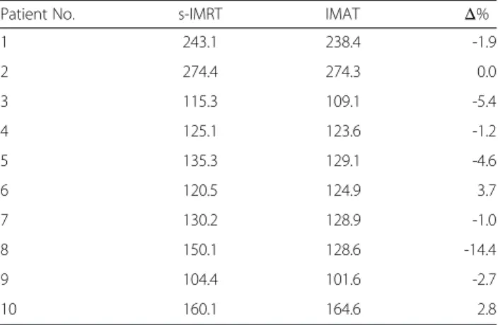
The integral dose inside the patient was lower for IMAT in 7 patients with a maximum difference of 14.4 % (Table 4). For 2 cases, IMAT integral dose was with 2.8 and 3.7 % higher, while for one case it was similar.
Fig. 1Radar charts of dose/volume levels comparing s-IMRT and IMAT plans summed on the pretreatment CT for a patient with a cT4a pN2 cM0 oropharynx cancer. The areas are formed by connecting the values belonging to one of the two treatment strategies.Abbreviations:s-IMRT = step-and-shoot IMRT; IMAT = intensity modulated arc therapy; GTVT= gross tumor volume of the primary tumor; GTVN= GTV of the metastatic lymph nodes; CTVHR= high risk clinical target volume; PTVHR= high risk planning target volume; CTVEN= elective neck CTV; PTVEN= elective neck PTV; PRV = planning organ-at-risk volume; SS = swallowing structures–includes superior pharyngeal constrictor, middle pharyngeal constrictor, inferior pharyngeal constrictor, upper esophageal sphincter, supraglottic larynx and upper 2 cm of the esophagus; PC = pharyngeal constrictors–includes superior pharyngeal constrictor, middle pharyngeal constrictor and inferior pharyngeal constrictor; Dx%= dose received by x% of the volume; V27Gy= % of the volume that receives at least 27 Gy
Delivery results
The data on dosimetric verification of treatment plans, number of MUs and delivery time are presented in Table 5. The number of MUs was significantly higher for IMAT than for s-IMRT plans. All treatments were delivered on the Elekta linacs while measuring with
the Delta4 system. Mean percentages of the points
with gamma index >1 were 99.7 ± 0.6 % versus 98.7 ± 1.3 % for s-IMRT and IMAT, respectively. On average, s-IMRT treatment times of phases I, II and III were 6:52, 6:39 and 5:00 min, respectively. IMAT delivery was significantly shorter: 4:13, 3:44 and 2:56 min, respectively.
Discussion
In this study we demonstrated the feasibility of a new
18
F-FDG-PET-voxel intensity-based IMAT class solution in our adaptive dose-painting strategy. DPBN imposes heavy demands to treatment planning and delivery technology in-cluding high dose gradients and high degree of fluence modulation. Until now18F-FDG-PET-voxel intensity-based s-IMRT has been used in DPBN trials for head-and-neck cancer [7, 8]. Probably due to limited modulation of s-IMRT in comparison to IMAT, biologic conformity of s-IMRT-based DPBN plans was not systematic. Severe toxicity was also experienced with DPBN-based dose escalation s-IMRT treatments [7] e.g. mucosal ulcers and dysphagia. Preliminary data from our clinical trials suggests that severe toxicity was correlated with dose-escalation and with smoking and alcohol abuse during and after treatment. There was no indication that severe toxicity could be caused by IMRT or the dose painting concept itself. The search to decrease the toxicity of dose-escalated treatments by reducing the OAR doses lead to the development of 18F-FDG-PET-voxel intensity-based IMAT.
We proposed a method using multiple partial arcs that would ensure higher flexibility and better conformity in dose distributions. In IMAT plans, the dose-painting quality factor evaluating biologic conformity of treat-ment plans showed significantly better values than for s-IMRT plans. Although most of the differences in D2%
and D98%for the target structures were significant, they
were not clinically relevant on both individual and aver-age patient data.
Previous studies showed that in complex-shaped tar-gets as head-and-neck cancer using a single arc was not sufficient to reach the quality of IMRT plans [15]. Most publications report similar or slightly better IMAT plans (dose coverage and homogeneity in targets) in comparison with dynamic IMRT or static IMRT at Table 3Quality factors (%) of s-IMRT and IMAT dose-painting by
numbers plans of the first two treatment phases
Phase I Phase II
sIMRT IMAT sIMRT IMAT
Patient 1 GTVT 5.1 3.9 4.3 2.8 GTVN1 1.8 1.5 4.6 1.4 GTVN2 2.8 2.0 Patient 2 GTVT 5.0 3.6 4.0 3.2 GTVN1 3.1 2.9 5.3 3.8 Patient 3 GTVT 4.3 2.8 3.6 2.2 Patient 4 GTVT 4.0 4.5 2.6 3.4 Patient 5 GTVT 5.1 3.5 4.5 3.1 Patient 6 GTVT 4.6 2.9 3.2 2.8 Patient 7 GTVT 3.8 4.1 3.4 2.9 Patient 8 GTVT 4.0 2.3 4.9 2.8 GTVN1 2.2 2.5 GTVN2 2.6 2.7 Patient 9 GTVT 3.5 1.9 2.8 1.4 Patient 10 GTVT 5.1 4.1 5.1 4.2 GTVN1 3.9 3.4 5.1 2.4
Dose painting inside GTVNwas done only for the cases where the PET signal
was high enough
Abbreviations:s-IMRTstep-and-shoot IMRT,IMATintensity modulated arc therapy,GTVTgross tumor volume of the primary tumor,GTVNxmetastatic
18
F-FDG-PET-positive lymph node
Table 4Integral Dose (J) calculated on the pretreatment CT scans inside the patient volume
Patient No. s-IMRT IMAT Δ%
1 243.1 238.4 -1.9 2 274.4 274.3 0.0 3 115.3 109.1 -5.4 4 125.1 123.6 -1.2 5 135.3 129.1 -4.6 6 120.5 124.9 3.7 7 130.2 128.9 -1.0 8 150.1 128.6 -14.4 9 104.4 101.6 -2.7 10 160.1 164.6 2.8
Abbreviations:s-IMRTstep-and-shoot IMRT,IMATintensity modulated arc therapy
conventional dose prescription, when double or triple full arcs were used [4, 5, 15–20].
IMAT has the potential to decrease doses to OARs [4, 5, 15–21] that becomes crucially important in dose-escalation treatment protocols. In s-IMRT plans we usually sacrifice the ipsilateral parotid, if the tumor or metastatic lymph node is at the level of the gland. A previous study [22] showed that adapting treatment to anatomic changes in the glands could lower doses even in the ipsilateral parotid. The current study results
demonstrate that IMAT could further spare both pa-rotids by significantly reducing Dmean (by 14.0 % and
12.7 % for the ipsilateral and contralateral parotid, re-spectively) and V27Gy(by 16.4 % and 17.5 % for the
ipsi-lateral and contraipsi-lateral parotid, respectively) as compared to s-IMRT, both treatments being adaptive. Vanetti et al. [5] obtained a significant reduction of parotid Dmeanusing
two full arcs against dynamic IMRT by 14.0 % and 13.5 % for the ipsilateral and contralateral parotid, respectively. Other studies employing double or triple full arcs Table 5Delivery analysis of each treatment phase: number of monitor units (MUs), treatment time (minutes:seconds) - registered from the beginning of the first beam till the end of the last beam - and the percentage of the measurement points withγ< 1 -which compares Delta4measurements and Pinnacle dose calculations
Patient Phase Number of MUs Treatment time % of points withγ< 1
s-IMRT IMAT s-IMRT IMAT s-IMRT IMAT
1 I 609 792 8:13 5:15 100.0 98.4 II 515 671 8:03 3:49 100.0 96.8 III 599 777 6:05 3:41 100.0 98.5 2 I 646 742 9:00 4:27 100.0 98.6 II 646 803 8:13 3:30 100.0 97.5 III 448 616 5:50 3:35 99.4 98.9 3 I 415 725 6:11 3:56 100.0 97.8 II 436 734 6:30 3:15 100.0 96.1 III 310 877 5:00 4:12 97.3 94.3 4 I 384 737 5:50 3:48 100.0 98.8 II 409 671 5:55 4:12 99.6 98.6 III 283 575 5:02 3:05 99.4 98.7 5 I 438 719 5:50 3:47 100.0 99.7 II 417 751 6:12 3:12 100.0 97.4 III 235 226 4:24 1:27 100.0 100.0 6 I 520 809 6:13 3:14 100.0 99.8 II 466 748 5:55 3:23 100.0 98.4 III 263 424 4:22 2:35 100.0 100.0 7 I 538 695 6:10 4:20 100.0 99.9 II 591 738 6:30 3:49 100.0 100.0 III 263 664 5:00 3:05 99.5 99.4 8 I 689 672 9:00 3:36 99.7 99.0 II 437 595 6:32 4:06 100.0 100.0 III 368 740 4:15 3:54 99.8 98.2 9 I 450 708 5:26 4:51 100.0 99.2 II 464 674 5:41 3:34 99.9 99.7 III 315 322 4:46 1:56 98.4 100.0 10 I 545 746 6:47 5:03 100.0 100.0 II 562 759 7:07 4:37 99.8 98.6 III 336 270 5:25 1:52 99.4 99.6 p-value < .0001 < .0001 < .0001
Two-sided Wilcoxon matched-pair signed rank testp-values are given on the last row Abbreviations:s-IMRTstep-and-shoot IMRT,IMATintensity modulated arc therapy
demonstrated similar contributions to parotid Dmean by
IMAT and IMRT [15, 16, 19]. With IMAT we could also better spare other OARs - the spinal cord, brainstem, pharyngeal constrictor muscles and swallowing structures -except the mandible (Table 2) a finding in agreement with Vanetti et al. [5]. Reduction in doses to OARs was even more evident in individual patients (Additional file 1: Figure S1 and Additional file 2: Figure S2).
Most retrospective [4, 5, 15–20] and prospective [21] IMAT-IMRT comparisons report a lower number of MUs for the arc therapy plans, although some report higher MUs [16, 26]. Our IMAT plans had on average higher MUs than IMRT plans, which might be of less concern due to the following reasons. The integral dose inside the patient (Table 4) showed that for IMAT plans the theoretical risk of developing secondary malignancies was less or similar to the s-IMRT plans. By delivering more dose to the surrounding tissues, based on the linear-non-threshold-model, an increase in secondary neoplasm can be expected [23]. Furthermore, the latest commer-cially available MLC devices are characterized with very low leakage and hence the overall patient exposure to low doses is highly reduced [24–26]. The linac head and MLC leakage is even further reduced in the case of flattening fil-ter free linacs [27].
Our IMAT plan measurements showed that a discrete dose calculation per 8° was not always a good approxi-mation of the arc delivery (data not shown). There are two reasons likely to cause the lower gamma index per-centages for the IMAT QA: one is the discretization (to a limited number of gantry angles) used in the dose computation, the second is the higher number of Monitor Units (MU) for the IMAT plans together with smaller fields. By CP refinement and further optimization, gamma percentages higher than 94.3 % could be achieved. The single arc plans of Bertelsen et al.[18] gave slightly better average percentages for gamma < 1 (99.6 ± 0.5 %) as com-pared to the multiple partial arc plans of the present study (98.7 ± 1.3 %). Korreman et al.[28] got 89.6 %, 88.5 % and 92.2 % for double arc plans corresponding to 3, 7 and 11 dose-painting-by-contours prescribed levels for one individual case. The reliability of Delta4 phantom mea-surements for IMRT and IMAT was studied by Bedford et al. [29]. We would like to point out that the spacing of 0.5 and 1 cm between the Delta4array detectors was rather limited for the high dose gradients of DPBN plans.
Rotational treatment shortens delivery time thus im-proving comfort for the patient and reducing risk of pa-tient movement during treatment, which cannot be neglected [30]. By eliminating parts of the arcs with very low contribution and linking them in one arc, IMAT treatment delivery time became in the range 1.3 to 5.2 min, which despite dose escalation, was comparable or even faster than published data on single, double or
triple full arc plans using conventional prescription doses to targets [5, 15–20].
Conclusions
IMAT implementation in an adaptive dose-escalation biological image-guided treatment strategy lead to sig-nificantly better biological quality factors in comparison to s-IMRT. The method was superior in reducing dose to OARs, biologic conformity and treatment efficacy. IMAT treatment delivery was significantly faster than s-IMRT and the multiple partial arc class solution made it one of the fastest reported in literature. Hence more pa-tients can be treated per day with more comfort and less intra-fraction movements.
Ethics approval and consent to participate
The data used in this manuscript are part of the study registerend on clinicaltrials.gov under NCT01341535. This study was approved by the Ethics Committe of Ghent University Hospital.
Additional files
Additional file 1: Figure S1.Individual patient IMAT and s-IMRT dose levels (D2%,D50%,D98%) for the volume of interest that comprises the pharyngeal constrictor muscles (PC) and the one that combines the swallowing structures (SS). Each graph presents the 10 individual patient values of one volume of interest dose level for the total summed dose distribution on the pretreatment CT. X and y axes show the s-IMRT and IMAT dose values (Gy). The marker position above or below the identity line (dotted) correspond to a higher or lower IMAT dose level value in comparison with s-IMRT, respectively.Abbreviations:s-IMRT = step-and-shoot IMRT; IMAT = intensity modulated arc therapy; PC = pharyngeal constrictor– includes superior pharyngeal constrictor, middle pharyngeal constrictor and inferior pharyngeal constrictor; SS = swallowing structures–includes superior pharyngeal constrictor, middle pharyngeal constrictor, inferior pharyngeal constrictor, upper esophageal sphincter, supraglottic larynx and upper 2 cm of the esophagus; Dx%= dose received by x% of the volume. (TIF 792 kb)
Additional file 2: Figure S2.s-IMRT (first row) and IMAT (second row) dose distributions for the 3 treatment phases of a patient with a cT4a pN2 cM0 oropharynx cancer. Isodoses are displayed on the CT transverse images. For phases I and II the contrast-enhanced18F-FDG-PET image set is superposed on the CT. The regions of interest contours are drawn as follows: GTVTand GTVNin red, CTVHRin purple, PTVHRin blue and the parotids in green (colorwash).Abbreviations:s-IMRT = step-and-shoot IMRT; IMAT = intensity modulated arc therapy; GTVT= gross tumor volume of the primary tumor; GTVN= GTV of the metastatic lymph nodes; CTVHR= high risk clinical target volume; PTVHR= high risk planning target volume. (TIF 1747 kb)
Abbreviations
18F-FDG-PET:2-deoxy-2-(18F)fluoro-D-glucose positron emitting tomography; ABAS: Elekta’s atlas-based autosegmentation; ABST: anatomy-based segmentation tool; BBST: biology-based segmentation tool; CPs: control points; CT: computed tomography; CTVHR: high risk clinical target volume; CTVEN: elective neck clinical target volume; Dmean: mean dose; DPBN: dose-painting-by-numbers; Dx%: dose received by x % of the volume; GTVNx: gross tumor volume of pathological lymph node(s); GTVT: gross tumor volume of the primary tumor; Gy: gray; IMAT: intensity-modulated arc therapy; MU: monitor unit; MV: megavolt; OAR: organ-at-risk; PC: pharyngeal constrictor; PRV: planning risk volume; PTVEN: elective neck planning target volume; PTVHR: high risk planning target volume; QF: quality factor;
ROI: region of interest; s-IMRT: step-and-shoot intensity modulated radiotherapy; SPSS: IBM statistical package for the social sciences; SS: swallowing structures; SUVMAX: maximal standardised uptake value; VxGy: volume receiving x Gy.
Competing interests
The authors declare that they have no competing interests.
Authors’contributions
DB helped including patients, helped in the target delineation and treatment planning of s-IMRT-plans, gathered the data and helped in the statistical analysis and writing of the manuscript. LO helped in the writing of the manuscript, treatment quality and statistical data analysis. LO also helped with the treatment delivery verification and in making the figures for the manuscript. BS made the IMAT treatment plans and helped in improving the delivery process. IM helped writing the manuscript and helped in the interpretation of the data. FD included patients, checked target and OARs delineations and helped in writing the manuscript. WDN participated in the design and coordination of the study and helped writing the manuscript. TV en WDG improved the treatment planning process, helped in writing the software to sum plans and did the quality analysis of treatment planning. WDG also helped writing the technical parts of this study. All authors read and approved the final manuscript.
Acknowledgments
This work is part of head-and-neck cancer research sponsored by scientific grants from the Agency for Innovation by Science and Technology, the Foundation against Cancer and the Flemish League against Cancer. The funding sources had no role in the design of the study or collection, analysis, or interpretation of data or in writing the manuscript.
The corresponding author confirms that he had full access to all the data in the study and has final responsibility for the decision to submit for publication. Author details
1
Department of Radiotherapy, Ghent University Hospital, De Pintelaan 185, 9000 Ghent, Belgium.2Department of Nuclear Medicine, Ghent University
Hospital, Ghent, Belgium.3Ghent University, Ghent, Belgium.4Zürich University Hospital, Zürich, Switzerland.
Received: 17 December 2015 Accepted: 28 March 2016
References
1. Nutting CM, Morden JP, Harrington KJ, et al. Parotid-sparing intensity modulated versus conventional radiotherapy in head and neck cancer (parsport): a phase 3 multicentre randomised controlled trial. Lancet Oncol. 2011;12(2):127–36.
2. Gupta T, Agarwal J, Jain S, et al. Three-dimensional conformal radiotherapy (3d-crt) versus intensity modulated radiation therapy (imrt) in squamous cell carcinoma of the head and neck: a randomized controlled trial. Radiother Oncol. 2012;104(3):343–8.
3. Kam MK, Leung SF, Zee B, et al. Prospective randomized study of intensity-modulated radiotherapy on salivary gland function in early-stage nasopharyngeal carcinoma patients. J Clin Oncol. 2007;25(31):4873–9. 4. Johnston M, Clifford S, Bromley R, et al. Volumetric-modulated arc therapy
in head and neck radiotherapy: a planning comparison using simultaneous integrated boost for nasopharynx and oropharynx carcinoma. Clin Oncol (R Coll Radiol). 2011;23(8):503–11.
5. Vanetti E, Clivio A, Nicolini G, et al. Volumetric modulated arc radiotherapy for carcinomas of the oro-pharynx, hypo-pharynx and larynx: a treatment planning comparison with fixed field imrt. Radiother Oncol. 2009;92(1):111–7. 6. Van Gestel D, van Vliet-Vroegindeweij C, Van den Heuvel F, et al. Rapidarc, smartarc and tomotherapy compared with classical step and shoot and sliding window intensity modulated radiotherapy in an oropharyngeal cancer treatment plan comparison. Radiat Oncol. 2013;8:37. 7. Duprez F, De Neve W, De Gersem W, et al. Adaptive dose painting by
numbers for head-and-neck cancer. Int J Radiat Oncol Biol Phys. 2011;80(4): 1045–55.
8. Berwouts D, Olteanu LA, Duprez F, et al. Three-phase adaptive dose-painting-by-numbers for head-and-neck cancer: Initial results of the phase i clinical trial. Radiother Oncol. 2013;107(3):310–6.
9. Vanderstraeten B, Duthoy W, De Gersem W, et al. [18f]fluoro-deoxy-glucose positron emission tomography ([18f]fdg-pet) voxel based intensity-modulated radiation therapy (imrt) for head and neck cancer. Radiother Oncol. 2006;79(3):249–58.
10. Gregoire V, Eisbruch A, Hamoir M, et al. Proposal for the delineation of the nodal ctv in the node-positive and the post-operative neck. Radiother Oncol. 2006;79(1):15–20.
11. De Gersem W, Claus F, De Wagter C, et al. An anatomy-based beam segmentation tool for intensity-modulated radiation therapy and its application to head-and-neck cancer. Int J Radiat Oncol Biol Phys. 2001;51(3):849–59.
12. De Gersem W, Claus F, De Wagter C, et al. Leaf position optimization for step-and-shoot imrt. Int J Radiat Oncol Biol Phys. 2001;51(5):1371–88. 13. Vercauteren T, De Gersem W, Olteanu LA, et al. Deformation field validation
and inversion applied to adaptive radiation therapy. Phys Med Biol. 2013; 58(15):5269–86.
14. Low DA, Harms WB, Mutic S, et al. A technique for the quantitative evaluation of dose distributions. Med Phys. 1998;25(5):656–61.
15. Verbakel WF, Cuijpers JP, Hoffmans D, et al. Volumetric intensity-modulated arc therapy vs. Conventional imrt in head-and-neck cancer: a comparative planning and dosimetric study. Int J Radiat Oncol Biol Phys. 2009;74(1):252–9. 16. Guckenberger M, Richter A, Krieger T, et al. Is a single arc sufficient in
volumetric-modulated arc therapy (vmat) for complex-shaped target volumes? Radiother Oncol. 2009;93(2):259–65.
17. Clemente S, Wu B, Sanguineti G, et al. Smartarc-based volumetric modulated arc therapy for oropharyngeal cancer: a dosimetric comparison with both intensity-modulated radiation therapy and helical tomotherapy. Int J Radiat Oncol Biol Phys. 2011;80(4):1248–55.
18. Bertelsen A, Hansen CR, Johansen J, et al. Single arc volumetric modulated arc therapy of head and neck cancer. Radiother Oncol. 2010;95(2):142–8. 19. Alvarez-Moret J, Pohl F, Koelbl O, et al. Evaluation of volumetric modulated
arc therapy (vmat) with oncentra masterplan(r) for the treatment of head and neck cancer. Radiat Oncol. 2010;5:110.
20. Rao M, Yang W, Chen F, et al. Comparison of elekta vmat with helical tomotherapy and fixed field imrt: Plan quality, delivery efficiency and accuracy. Med Phys. 2010;37(3):1350–9.
21. Fung-Kee-Fung SD, Hackett R, Hales L, et al. A prospective trial of volumetric intensity-modulated arc therapy vs conventional intensity modulated radiation therapy in advanced head and neck cancer. World J Clin Oncol. 2012;3(4):57–62.
22. Olteanu LA, Berwouts D, Madani I, et al. Comparative dosimetry of three-phase adaptive and non-adaptive dose-painting imrt for head-and-neck cancer. Radiother Oncol. 2014;111(3):348–53.
23. United States. General Accounting Office. Radiation Standards: Scientific Basis Inconclusive, and EPA and NRC Disagreement Continues. Washington D.C.: UNT Digital Library. http://digital.library.unt.edu/ark:/67531/ metadc290290/. Accessed 20 Mar 2016.
24. Van de Walle J, Martens C, Reynaert N, et al. Monte carlo model of the elekta sliplus accelerator: Validation of a new mlc component module in beam for a 6 mv beam. Phys Med Biol. 2003;48(3):371–85.
25. Thompson CM, Weston SJ, Cosgrove VC, et al. A dosimetric characterization of a novel linear accelerator collimator. Med Phys. 2014;41(3):031713. 26. Kantz S, Sohn M, Troeller A, et al. Impact of mlc properties and imrt
technique in meningioma and head-and-neck treatments. Radiat Oncol. 2015;10:184.
27. Georg D, Knoos T, McClean B. Current status and future perspective of flattening filter free photon beams. Med Phys. 2011;38(3):1280–93. 28. Korreman SS, Ulrich S, Bowen S, et al. Feasibility of dose painting using
volumetric modulated arc optimization and delivery. Acta Oncol. 2010;49(7): 964–71.
29. Hoogeman MS, Nuyttens JJ, Levendag PC, et al. Time dependence of intrafraction patient motion assessed by repeat stereoscopic imaging. Int J Radiat Oncol Biol Phys. 2008;70(2):609–18.
30. Bedford JL, Lee YK, Wai P, et al. Evaluation of the delta4phantom for IMRT and VMAT verification. Phys Med Biol. 2009;54(9):N167–76.