I
n 1747, Pierre Fauchard described the process by which roots of maxillary anterior teeth were selected for the restoration of single teeth and replacement of multiple teeth. Gold or silver pivots (posts) were retained in the roots with the use of a heat-softened adhesive called “mastic,” and crown replacements were attached to the pivots.1In 1766, Adam Anton Brunner described a method
of applying pivot teeth by screwing the pivot into the base of a crown, then enlarging the root canal enough to tightly embrace the root portion of the pivot.2Early
“pivot” crowns in the United States used seasoned white hickory wood for pivots.3Moisture would swell
the wood and restain the pivot.2 Subsequently, pivot
crowns were fabricated with a combination of wood and metal and then durable all-metal pivots. Metal pivot retention was achieved with threads, pins, surface roughening, and split designs that provided mechani-cal spring retention.2
With the use of pivots, replacement crowns were made from bone, ivory, animal teeth, and sound nat-ural tooth crowns.2These natural substances gradually
were replaced by porcelain. Porcelain pivot crowns were described in 1802 by Dubois de Chemant and became the preferred method for replacement of arti-ficial teeth.2
Clinical tooth preparations for pivot crowns focused
principles
Charles J. Goodacre, DDS, MSD,aWayne V. Campagni, DMD,band Steven A. Aquilino, DDS, MSc School of Dentistry, Loma Linda University, Loma Linda, Calif., and College of Dentistry, University of Iowa, Iowa City, Iowa
Statement of the problem. No recent literature has reviewed the current scientific knowledge on complete coverage tooth preparations.
Purpose. This article traces the historic evolution of complete coverage tooth preparations and identifies guidelines for scientific tooth preparations.
Material and methods. Literature covering 250 years of clinical practice was reviewed with emphasis on scientific data acquired during the last 50 years. Both a MEDLINE search and an extensive manual search were used to locate relevant articles written in English in the last 50 years.
Results. Teeth should be prepared so that they exhibit the following characteristics: 10 to 20 degrees of total occlusal convergence, a minimal occlusocervical dimension of 4 mm for molars and 3 mm for other teeth, and an occlusocervical-to-faciolingual dimension ratio of 0.4 or greater. Facioproximal and linguo-proximal line angles should be preserved whenever possible. When the above features are missing, the teeth should be modified with auxiliary resistance features such as axial grooves or boxes, preferably on proximal surfaces. Finish line selection should be based on the type of crown/retainer, esthetic require-ments, ease of formation, and personal experience. Expectations of enhanced marginal fit with certain finish lines could not be validated by recent research. Esthetic requirements and tooth conditions deter-mine finish line locations relative to the gingiva, with a supragingival location being more acceptable. Line angles should be rounded, and a reasonable degree of surface smoothness is desired.
Conclusion. Nine scientific principles have been developed that ensure mechanical, biologic, and esthet-ic success for tooth preparation of complete coverage restorations. (J Prosthet Dent 2001;85:363-76.)
Portions of this manuscript were presented before the annual meet-ing of the American Academy of Fixed Prosthodontics, Chicago, Ill., February 19, 1999, and the annual meeting of The American College of Prosthodontists, Orlando, Fla., November 6, 1997. aDean and Professor, Department of Restorative Dentistry, School of
Dentistry, Loma Linda University.
bDirector of Graduate Prosthodontics and Professor, Department of Restorative Dentistry, School of Dentistry, Loma Linda University.
cProfessor, Head and Graduate Director, Department of Prosthodontics, College of Dentistry, University of Iowa.
CLINICAL IMPLICATIONS
The principles identified in this article can help dentists design, assess, and modify complete coverage tooth preparations to ensure clinical success for the treatment of a variety of unprepared and previously prepared teeth.
on removal of residual coronal tooth structure with saw blades, excising forceps, and files, followed by formation of post spaces with broaches, burs, or spiral drills.2,3
When Charles Henry Land developed his technique for fabrication of porcelain jacket crowns, a change was required in the guidelines to prepare teeth because coronal tooth structure was preserved for crown reten-tion and pulpal vitality retained. He advocated porcelain jacket crowns because they preserved tooth structure,4-6 were more esthetic than pivot crowns,4
and reduced the number of tooth fractures associated with combined crown-post restorations.7Land
report-ed less impingement on soft tissue.5,6 He also
identified the importance of acceptable marginal fit6
and indicated that the clinical procedures were less painful to the patient and less fatiguing to the dentist.4
Thus, in early publications by Land,4-9 the biologic,
mechanical, esthetic, and psychologic advantages of preserving coronal tooth structure and performing conservative tooth reduction were first presented. However, specific details regarding the form of a pre-pared tooth and written guidelines on tooth preparation were not included in these publications.
During subsequent years, various aspects of tooth preparation design were cited in the literature. The first feature discussed extensively was forms of finish lines. Dr Edward Spalding adopted Dr Land’s princi-ples, and they jointly developed the concept of a complete shoulder finish line that provided the all-ceramic crown with uniform thickness and facilitated platinum foil matrix adaptation. Dr Spalding’s 1904 article10was the first to describe the all-ceramic crown
fabrication process in detail and clearly illustrate a shoulder finish line.
In the 1920s and 1930s, articles were published with regard to these relatively new porcelain jacket crowns and the preparation design for the coronal
tooth structure. Considerable focus was still directed toward the most appropriate finish line. Articles were published promoting different variations of shoulder finish lines.11-14 Shoulder finish lines were advocated
because of increased restoration strength,15 porcelain
bulk and marginal strength,13,16and fabrication
accu-racy.17Shoulderless tooth preparations with a tapering
finish line also were promoted, as were shoulders with a marginal bevel.18
On the basis of this early dental literature, it was apparent that many persons considered tooth prepara-tions and finish lines important factors that affected the clinical longevity of porcelain jacket crowns.11,15,16,19-21 Nevertheless, different opinions
existed for the optimal form, and no scientific data were available. The same conditions prevailed as other types of restorations and associated tooth preparations were developed in later years. It was not until the 1950s and 1960s that scientific studies began to ana-lyze tooth preparations and identify features that were essential for success.
This article presents guidelines for complete tooth preparations based on current scientific evidence. Through a review of the dental literature, several crit-ical aspects of tooth preparation have been identified. These critical items warrant discussion so that guide-lines that promote the creation of mechanically, biologically, and esthetically sound tooth preparations can be developed.
TOOTH PREPARATION GUIDELINES 1: Total occlusal convergence
Total occlusal convergence (TOC) (the angle of convergence between 2 opposing prepared axial sur-faces) was one of the first aspects of tooth preparations for complete crowns to receive specific numeric recom-mendations. In 1923, Prothero2 indicated that “the
Fig. 1. Diagram with associated vertical linesrepresenting total occlusal convergence (TOC) of axial walls when prepared with 5-, 10-, 15-, 20-, and 25-degree TOCs.
convergence of peripheral surfaces should range from 2°-5°,” but more than 30 years would pass before this specific recommendation was subjected to scientific scrutiny. In 1955, Jorgenson22tested the retention of
crowns at various TOC angles by applying a tensile force to a cemented crown. Maximal tensile retentive values were recorded at 5 degrees TOC, supporting earlier 2- to 5-degree recommendations. In addition, other authors23-26 have recommended minimal TOC
angles (between 2 degrees and 6 degrees). Wilson and Chan27reported in 1994 that maximal tensile retention
occurred between 6 and 12 degrees TOC.
A critical factor that must be assessed for the devel-opment of a guideline for TOC is the actual angle formed when teeth are prepared. Many dentists have assumed that the convergence angles they produce meet the recommended 2- to 6-degree minimal angle. However, it is important to objectively evaluate con-vergence angles typically established on various teeth. Figure 1 has been created to assist this evaluation process. Placing a prepared tooth die in a position where the axial walls of the die can be superimposed over the lines present in the figure permits close approximations of the TOC.
Occlusal views typically are used clinically to assess TOC but are of limited value for determining the actu-al convergence angle formed (Fig. 2). Therefore, during clinical tooth preparation, the use of a mirror has been recommended so that a facial or lingual view of the prepared teeth is established. Facial/lingual clinical views are the most effective means of assessing TOC because the convergence of mesial and distal sur-faces is readily visible.
It has been determined that dental students, general practice residents, general dentists, and prosthodontists do not routinely create minimal angles such as 2 to 5 degrees28-37(Fig. 3). Studies by Weed et al,28Smith et
al,29Noonan and Goldfogel,30Ohm and Silness,31and
Annerstedt et al32 reported mean TOC angles that
ranged from 12.2 to 27 degrees, depending on whether the tooth preparations were completed in the preclinical laboratory or in clinical situations. Overall, lower TOC angles were prepared in preclinical situations and during examinations. When tooth preparations by students were compared with those by general dentists, Annerstedt et al32 revealed that the mean TOC for
dental students (19.4 degrees) was less than the con-vergence created by dentists (22.1 degrees). Similar studies have reported mean TOC angles ranging from 14.3 to 20.1 degrees for dentists with no apparent cor-relation to their level of education or experience.33-37
The dental literature has also presented data on sev-eral factors likely to create greater TOC and perhaps even necessitate the formation of auxiliary characteris-tics that enhance resistance to dislodgement:
1. Posterior teeth were prepared with greater TOC than anterior teeth32,33,37(Fig. 3, Athrough C).
2. Mandibular teeth were prepared with greater con-vergence than maxillary teeth.29,33,37
3. Mandibular molars were prepared with the great-est TOC.34,37
4. Faciolingual surfaces had greater convergence than mesiodistal surfaces (Fig. 4).32However, another
study37 determined that mesiodistal convergence
was greater than faciolingual convergence. 5. Fixed partial denture (FPD) abutments were
pre-pared with greater TOC than individual crowns.35
6. Monocular vision (1 eye) created greater TOC than binocular vision (both eyes).35 Although it
has been demonstrated that binocular vision, at very short tooth-to-eye distances (150 mm or approximately 6 in.),35causes teeth to be
under-cut by an average of 5 degrees, teeth are clinically prepared at distances greater than 150 mm even
Fig. 2. A, Occlusal view of maxillary premolar and molar prepared for partial coverage crowns. B,Lingual view of premolar and molar. Note that molar has been prepared with much greater TOC (20 degrees) than premolar (7 degrees). Greater convergence of molar is easier to assess with use of lingual view.
B
A
when magnification loupes are used. Therefore, binocular vision has been more likely than monoc-ular vision to create minimal clinical convergence. More recently, resistance to lateral forces and not
retention along the path of insertion has been advo-cated as the determining factor in a crown’s resistance to dislodgement.38-40When testing both the retention
and resistance of crowns cemented on metal dies, it was concluded that resistance testing was more sensi-tive than retensensi-tive testing to changes in convergence angle.39 Therefore, laboratory tests have become
focused on resistance testing through the application of simulated lateral forces.
Dodge et al39tested the tipping resistance of
artifi-cial crowns cemented over teeth with 10, 16, and 22 degrees TOC that were 3.5 mm in occlusocervical dimension and 10 mm in diameter, similar to prepared molars. They reported that 22 degrees of TOC pro-duced inadequate resistance and that there was no significant difference between the resistance of 10- and 16-degree specimens. They concluded that 16 degrees was the optimal convergence angle of the 3 tested because 10 degrees of TOC was not easy to create clin-ically. Shillingburg et al41recently suggested that the
TOC should be between 10 and 22 degrees. A guide-line for total occlusal convergence should list numeric values that: (1) are achievable in a preclinical laborato-ry and during clinical tooth reduction, and (2) provide adequate resistance to the dislodgement of
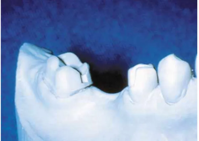
restora-Fig. 3. A, Facial view of maxillary central incisor prepared for all-ceramic crown. TOC between mesial and distal walls is 5 degrees. Smallest TOC angles typically are produced on anterior teeth because of their access and visibility. B,Cast of mandibular molar prepared with 7 degrees of TOC, representative of smallest TOC angle produced by authors on poste-rior teeth. C,Facial view of mandibular molar with 18 degrees of TOC, representative of many posterior teeth prepared by authors. D, Casts of mandibular premolar and molar. Greater convergence was created on less accessible teeth (molars) than on premolars. Premolar TOC is 12 degrees and molar TOC is 22 degrees. E, Cast of mesially inclined mandibular molar and resulting tooth preparations. When abutments were moderately to severely malaligned, greater TOC angles frequently were created. Premolar has 18 degrees of TOC and molar has 24 degrees of TOC.
B
A
C
E
D
Fig. 4. Occlusal view of maxillary central incisor, canine, and molar prepared for long-span prosthesis. Facial and lingual surfaces of teeth had considerable convergence before tooth preparation; therefore, faciolingual convergence of complet-ed preparations was greater than mesiodistal convergence.
tions when coupled with other tooth preparation design guidelines. Therefore, it is proposed that TOC ideally should range between 10 and 20 degrees.
2: Occlusocervical/incisocervical dimension
Parker et al42,43 calculated “critical convergence
angles” beyond which a crown theoretically would not possess adequate resistance to dislodgement. In con-trast, Wiskott et al38,40 determined that a linear
relationship exists between convergence angles and a crown’s resistance to dislodgement; they questioned the validity of a critical convergence angle beyond which failure occurs. Recently, Trier et al44tested the
concept of a limiting convergence angle by evaluating the resistance form of 44 dies when the restorations had failed clinically through loosening from the pre-pared tooth. Of the 44 dies, 42 lacked resistance form, supporting a relationship between clinical success/fail-ure and the all-or-none concept of a limiting convergence angle.
The calculations of Parker et al43 with regard to
critical convergence indicated that resistance to dis-lodgement was adequate when a 10-mm diameter molar tooth preparation possessed 3 mm of occlu-socervical (OC) dimension and 17.4 degrees or less of TOC. Preparation heights of 1 and 2 mm for a 10-mm diameter tooth preparation required 5.8- and 11.6-degree TOC angles, respectively. Given the typical TOC angles that have been measured from clinical preparations, 17.4-degree TOC appears to be an achievable angle; therefore, 3 mm would be an appro-priate minimal OC dimension according to Parker’s calculations.
Maxwell et al45 tested the resistance of artificial
crowns that were 1, 2, 3, and 5 mm in OC dimension and had minimal (6 degrees) TOC. They concluded that 3 mm was the minimal OC dimension required to provide adequate resistance for crowns made to fit teeth the size of maxillary incisors and mandibular pre-molars prepared with minimal TOC.
Woolsey and Matich46recorded resistance of
unce-mented crowns dislodged from dies. Three millimeters of OC dimension was found to provide adequate resis-tance but only at 10 degrees TOC. However, 3 mm of OC dimension provided inadequate resistance at 20 degrees TOC, an angle frequently formed on many molars. This study supports formation of an OC dimension greater than 3 mm on molars.
Therefore, it is proposed that 3 mm is the minimal OC dimension for premolars and anterior teeth that are prepared within the recommended TOC range of 10 to 20 degrees. Because molars usually are prepared with greater convergence than anterior teeth, have a greater diameter than other teeth, and are located where occlusal forces are greater, 4 mm is proposed as the minimal OC dimension for prepared molars (Fig. 5).
Teeth that do not possess these minimal dimensions should be modified with auxiliary resistance features such as grooves/boxes.
3: Ratio of occlusocervical/incisocervical dimension to faciolingual dimension
The horizontal components of a masticatory cycle and parafunctional habits develop forces on individual crowns and FPDs that are customarily faciolingual (FL) in direction. This dimension of the prepared tooth should be a primary focus of ratio calculations.
When evaluating the resistance of 294 single artificial crowns to dislodgement from their dies, it was deter-mined that 96% of incisor crowns, 92% of canine crowns, and 81% of premolar crowns displayed ade-quate resistance despite variations in the prepared tooth form and dimensions.47 One factor critical to creating
this adequate resistance was favorable OC/FL ratios of incisors, canines, and premolars because of their typical anatomic dimensions when prepared (Fig. 6). However, only 46% of molars possessed appropriate resistance. The larger faciolingual dimension of prepared molars compared with other teeth and shorter occlusocervical dimension of many prepared molars compared with anterior teeth and premolars produces a lower ratio and poorer resistance to dislodgement of a molar crown. The greater total occlusal convergence usually formed on molars32,33,37also accentuates the ratio problem.
Theoretical calculations43 indicate that adequate
resistance can be achieved with an OC/FL ratio of 0.1 when the TOC is less than 5.8 degrees. A ratio of 0.2 requires the TOC to be less than 11.6 degrees; a ratio of 0.3 requires less than 17.4 degrees of TOC; and a
Fig. 5. Occlusocervical dimension of mandibular second premolar and first molar measured with periodontal probe to determine whether 4 mm minimal dimension for molars has been satisfied. Note that prepared proximal wall is only 2 mm high even though facial surface has adequate TOC dimension.
ratio of 0.4 provides adequate resistance as long as the TOC angle is 23.6 degrees or less.43
Weed and Baez48 presented a diagram for
deter-mining the taper (1⁄
2the TOC) of a tooth preparation
that provides resistance form based on the occlu-socervical/incisocervical (OC/IC) crown dimension and its diameter. To test the validity of the diagram, 50 metal dies were made with 5 different conver-gence angles and gold copings cast for each die. Inadequate crown resistance was present with a die that was 10 mm in diameter and 3.5 mm in OC dimension and that possessed 22 degrees TOC. This indicated that a 0.35 ratio was inadequate for teeth
with dimensions representative of many prepared molars.
Therefore, it is recommended that the OC/FL ratio should be 0.4 or higher for all teeth.
4: Circumferential morphology
After anatomic reduction, most teeth have specific geometric forms when viewed occlusally. For example, prepared mandibular molars are rectangular in form, maxillary molars are rhomboidal, and premolars and anterior teeth frequently possess an oval form. These geometric shapes have traditionally provided resistance to dislodging forces on individual crowns and FPDs.
Hegdahl and Silness49compared the areas that
cre-ated resistance form on conical and pyramidal tooth preparations. The pyramidal tooth preparations pro-vided increased resistance because they possessed “corners” when compared with the conical prepara-tions. It is important to preserve the facioproximal and linguoproximal “corners” of a tooth preparation. Teeth that lack natural circumferential morphologic variations after tooth preparation (round teeth) should be modified with the creation of grooves or boxes in axial surfaces. These features can provide resistance to dislodgement while physically engaging the prepared tooth (Fig. 7).
Kent et al37 determined that grooves and boxes,
when placed in prepared axial surfaces, had significant-ly less TOC (7.3 degrees) than the convergence of the axial walls (14.3 degrees) and thereby enhanced resis-tance form. Molars are usually prepared with greater occlusal convergence than premolars and anterior teeth33 and possess a shorter occlusocervical
dimen-sion than other teeth. Molars also have a less favorable OC/FL dimension ratio. For these reasons, they could benefit from auxiliary tooth preparations. Parker et
Fig. 6. A,Maxillary 6 anterior teeth prepared for metal-ceramic crowns. After tooth reduction, teeth had favorable ratio of IC dimension to FL dimension due to normal dimensions of teeth before reduction. B, Maxillary premolars and molars prepared for metal-ceramic crowns. Note that molars were shorter occlusocervically than premolars due to naturally shorter OC dimension before reduction. Shorter OC dimension of molar teeth coupled with larger FL dimension frequently creates unfavorable OC/FL dimension ratio.
B
A
Fig. 7. Three maxillary and 3 mandibular teeth prepared for complete coverage restorations. “Preserved corners” of teeth are particularly evident on 3 maxillary tooth prepara-tions. Shoulder finish lines were used for maxillary metal-ceramic crowns and chamfer finish lines for mandibular all-metal crowns.
al47 reported that only 8 of 107 molar dies had
grooves and, overall, 54% of the molar castings had inadequate resistance. Therefore, axial grooves or boxes are frequently needed with molars to augment their resistance form.
In addition, research has determined that mandibu-lar momandibu-lars sometimes are prepared with greater convergence than maxillary molars33,37 and that
mandibular molars are the teeth prepared with the greatest convergence angles.34-37 These data have
been linked with increased occlusal forces and mandibular flexion. It therefore is recommended that axial grooves/boxes be routinely used when mandibu-lar momandibu-lars are prepared for FPDs (Fig. 8).
Resistance to lateral forces commonly is the determining factor in a crown’s resistance to
dis-lodgement.38-40 Horizontal components of
masticatory cycles and parafunctional habits direct forces on single crowns and FPDs that are faciolin-gual in character. Therefore, consideration should be given to the most appropriate location for auxil-iar y retentive features. Woolsey and Matich46
determined that proximal grooves provided com-plete resistance to faciolingual forces, whereas facial or lingual grooves provided only partial resistance to faciolingual dislodgement. Mack35disclosed that
mesiodistal surfaces are prepared with less TOC than faciolingual surfaces; hence, auxiliary grooves in proximal surfaces are more likely to be aligned with the more ideal convergence angles of proximal surfaces. Therefore, auxiliar y grooves/boxes designed to augment resistance form should be located on the proximal surfaces of FPD abutments.
5: Finish line location
Many studies have supported the use of supragingi-val finish lines whenever possible to ensure periodontal health.50-58 However, subgingival finish lines
fre-quently are required for the following reasons: to achieve adequate OC dimension for retention and resistance form; to extend beyond dental caries, frac-tures, or erosion/abrasion or to encompass a variety of tooth structure defects; to produce a cervical crown ferrule on endodontically treated teeth; and to improve the esthetics of discolored teeth and certain restorations. Studies59-61 have indicated that
peri-odontal health can be retained in intracrevicular margins, but it requires properly contoured restora-tions with satisfactory margins and careful treatment of the hard and soft tissues associated with tooth prepa-ration (Fig. 3, A).
When a subgingival finish line is required, it has been suggested that extension to the epithelial attach-ment be avoided. Waerhaug,62 based on analyses of
animal (dog) and human autopsies, indicated that crown margins did not cause pocket deepening if
mar-gins were at least 0.4 mm occlusal to the base of the gingival crevice. Newcomb57reported that when
sub-gingival margins approached the base of the sub-gingival crevice, more severe gingivitis occurred. Garguilo et al63
proposed that the dimension of the epithelial attach-ment combined with the dimension of the connective tissue attachment occlusal/incisal to bone should be approximately 2 mm. Cohen and Ross64discussed this
relationship and suggested the term biologic width. Nevins65 indicated that placement of a restoration into
this zone could compromise periodontal health. Carnevale et al66extended crown margins to the bone
crest in dogs and noted loss of 1.0 mm of crestal bone.
Fig. 8. Cast of mandibular molar retainer tooth preparation incorporating mesial box to increase resistance form.
Fig. 9. Chamfer finish line formed with tapered round-end diamond instrument. Chamfer finish lines usually are selected for all-metal crowns because they are visually dis-tinct and easy to form. To create chamfer finish line, depth was first established (equaling one-half instrument tip diam-eter), and that dimension was maintained as instrument was moved around axial surfaces. Chamfer depth of 0.3 mm was desired, so diamond instrument with 0.6-mm tip diam-eter was used.
Tarnow et al67 placed subgingival finish lines and
provisional crowns on 13 teeth in 2 patients. The mar-gins were located half-way between the facial gingival crest and the bone crest. Clinical gingival recession (0.9 mm average with 0.4-1.2 mm range) was observed within 2 weeks, and an average recession of 1.2 mm was recorded within 8 weeks. The histologic analysis indicated that recession mechanisms were acti-vated within the first 7 days, that reformation of the intracrevicular and junctional epithelium occurred, that the reformed junctional epithelium was located apical to the finish line bevel, and that there was cres-tal bone resorption. Kois68 proposed a variation of
biologic width that he termed dentogingival complex dimension because it included the epithelial attach-ment, connective tissue attachattach-ment, and gingival sulcus depth.
OC variations in finish lines occur on most prepared teeth because of normal changes in the position of a gingival crest around the circumference of teeth. With all-ceramic crowns tested in the laboratory, OC varia-tions in the finish line location have reduced restoration strength.69 When gingival position
per-mits, location of the finish lines close to the identical OC locations on all axial surfaces increases all-ceramic crown strengths. Making the proximal finish lines as level as possible faciolingually also reduces stress.70
However, these recommendations should be superceded by an intention to minimize subgingival extensions of dental restorations.
Finish lines should be located supragingivally when retention and resistance form, tooth condition, and esthetics permit. When subgingival finish lines are required, they should not be extended to epithelial attachments.
6: Finish line form and depth
All-metal restorations. Chamfer finish lines fre-quently have been used for all-metal crowns. No scientific studies have stated that chamfers are superior to other finish lines. However, they are used with all-metal crowns because they are easy to form with a tapered, round-end diamond instrument and because they are distinct, being readily visible on the prepared tooth, impression, and die (Fig. 9). Chamfers also pos-sess adequate bulk for restorative rigidity, and their depth is sufficient to permit the development of nor-mal axial contours. Therefore, chamfer finish lines are well suited for all-metal crowns.
Recommended chamfer depth is determined by the minimal metal thickness for strength and minimal space required to develop a physiologic emergence profile. Authors have recommended chamfer finish line reduction depths of 0.3 to 0.5 mm.24,26 These
recommendations were based on experience in labora-tory fabrication of all-metal crowns. To test the validity
of these experience-based guidelines, the faciolingual dimension of 67 wax patterns made on dies with either a feather-edge finish line or a 0.3-mm deep chamfer finish line were measured. The patterns were formed by 57 students and 10 dental laboratory technicians. The dimensions of the wax patterns were compared with the unprepared tooth dimensions. When the 0.3-mm deep chamfer finish line (Fig. 7) was used, the average faciolingual pattern dimension closely approximated the unprepared tooth. The feather edge finish lines pro-duced patterns that were an average of 0.6 mm larger than the unprepared tooth. Therefore, it is recom-mended that chamfer finish lines for all-metal crowns possess a minimum depth of approximately 0.3 mm.
Metal-ceramic restorations. The following types of finish lines historically have been used with metal-ceramic crowns: chamfer, beveled chamfer, shoulder (Fig. 10), and beveled shoulder. Two initial research articles71,72 indicated that when porcelain was fused
on metal frameworks, it produced significantly greater marginal metal distortion when a chamfer finish line was used. Although the distortion differences were sta-tistically significant, the clinical relevance could be questioned because the magnitudes of distortion were all less than 50 µm. In addition, subsequent studies failed to show statistical significance. Hamaguchi et al73 recorded no significant difference in marginal
metal distortion resulting from the fusion of porcelain when they compared shoulder, shoulder-bevel, cham-fer, and chamfer-bevel finish lines. Likewise, Richter-Snapp et al74 discovered that finish lines did
not significantly affect the fit of metal-ceramic crowns after porcelain fusion. Syu et al75reported no
signifi-cant differences between the axial and marginal fit of tooth preparations with shoulder, shoulder-bevel, and chamfer finish lines. Belser et al76compared the
mar-ginal fit of crowns with a metal shoulder-bevel, a metal shoulder, and a porcelain shoulder before and after cementation. No significant differences were found between finish lines either before or after cementation. Byrne77collaborated the data relative to the effect of
cementation and determined that finish line form did not affect the fit of cemented crowns. On the basis of the previously discussed studies, it can be concluded that the selection of finish lines used with metal-ceramic crowns should not be based on marginal fit but on personal preference, esthetics, ease of forma-tion, and the type of metal-ceramic crown (metal marginal collar vs collarless design) being fabricated.
Recommended metal-ceramic finish line depths are based on the minimal material thickness required for strength and esthetics as well as the minimal space required to develop a physiologic emergence profile. Authors23-26, 41,78often have recommended
thickness-es between 1.0 and 1.5 mm for the porcelain-veneered marginal area of a metal-ceramic crown. Multiple
stud-ies79-81have indicated that at least 1.0 mm of
translu-cent porcelain (not including metal and opaque) is required to reproduce the color of a shade guide. This research indicates that tooth reductions in excess of 1.0 mm are needed. One study81 determined that a
thickness between 1.4 mm and greater than 2.0 mm of translucent porcelain is needed for metal-ceramic crowns to match the shade guide.
Variations exist between recommended tooth reduction depths and those actually created. One study82of the actual finish line depth prepared on 24
extracted human teeth by 3 dentists discovered a mean shoulder depth of 0.75 mm (± 0.17 mm). In addition, 1 researcher measured 34 consecutive dies submitted by students to the in-house dental laboratory for fabrica-tion of metal-ceramic crowns. The mean finish line depth recorded was 0.9 mm with a range of 0.5 to 1.8 mm. These data indicated that finish line depths greater than 1.0 mm were not routinely prepared (Fig. 10).
Although metal-ceramic finish line depths of 1.0 mm or more are recommended, the routinely achievable optimal clinical depth has not been determined.
All-ceramic crowns. All-ceramic crown strengths have been investigated in relation to the finish line. Friedlander et al83 and Doyle et al84 measured the
strength of all-ceramic crowns made for prepared max-illary premolars with chamfer finish lines, shoulders with sharp axiogingival line angles, and shoulders with rounded axiogingival line angles. The laboratory data with crowns cemented on metal dies showed that crowns with chamfer finish lines were significantly weaker, supporting a similar laboratory finding by Sjogren and Bergman.85 However, when all-ceramic
crowns were internally etched and cemented on natur-al teeth with a resinous cement, there was no significant strength reduction in a laboratory study86
or in a longitudinal retrospective clinical evaluation87
of all-ceramic crowns. Therefore, shoulder finish lines (Fig. 11) are recommended for all-ceramic crowns that are not etched and bonded to the teeth. Either shoul-der or chamfer finish lines can be selected for all-ceramic crowns bonded to prepared teeth.
Recommended finish line depths for all-ceramic crowns have ranged from 0.5 to 1.0 mm23-26,41,78
(Fig. 11). It has been determined81 that for the
ceramic thickness to match shade tabs, there is lim-ited improvement when thickness of semi-translucent all-ceramic systems (Empress, Ivoclar/ Williams, Amherst, N.Y., and InCeram Spinal, Vident, Brea, Calif.) is increased beyond 1 mm. However, with a more opaceous system such as InCeram alumina, an increase of ceramic thickness that exceeded 1 mm elevated the shade-matching
potential.81 It has not been advantageous to
increase all-ceramic crown finish line depth beyond
1 mm with the use of a semitranslucent all-ceramic material.
7: Axial and incisal/occlusal reduction depths
The required depth of reduction varies with differ-ent types of crowns and various surfaces of a tooth. Reduction also is affected by the position and align-ment of teeth in the arch, occlusal relationships, esthetics, periodontal considerations, and tooth mor-phology. For instance, a maxillary central incisor with considerable cervical convergence to the clinical crown (viewed facially) requires greater overall proximal reduction during tooth preparation of specific finish line depths than a square-shaped tooth, which has less convergence between the incisal edge and gingiva. Deep occlusal interdigitation of posterior teeth or
Fig. 10. Maxillary canine prepared for metal-ceramic FPD. Shoulder finish line with depth of 0.9 mm. Mesial proximal groove was added to tooth preparation to enhance resis-tance form because of relatively short lingual wall.
Fig. 11. Maxillary central incisor prepared for all-ceramic crown with use of shoulder finish line with sharp axiogin-gival line angle. Finish line depth was 0.8 mm.
appreciable vertical overlap of the anterior teeth often necessities greater overall reduction of occluding sur-faces. Malaligned teeth commonly have required greater reduction of protruding surfaces to permit restoration alignment and/or satisfactory retention and resistance form.
Periodontal health is enhanced through the develop-ment of normal cervical crown contours, but overcontoured restorations promote plaque accumula-tion. Overcontoured restorations can result in periodontal problems, so reduction depth ideally should permit the simultaneous development of normal con-tours, appropriate esthetics, and adequate strength.
All-metal restorations. Only anecdotal clinical and laboratory experience exists to support proposed reductions of the occlusal and facial/lingual axial sur-faces. It is believed that 0.5 to 0.8 mm of reduction near the occlusal surface of facial/lingual surfaces pro-vides sufficient space for the fabrication of all-metal crowns with normal contours and sufficient rigidity to resist flexion from occlusal forces. Experience also indicates that occlusal reduction depths less than 1 mm often compromise occlusal ridge height, fossa depth, and the depth and direction of grooves in the restora-tion. Underprepared restorations frequently possess relatively flat occlusal morphology, particularly after clinical occlusal adjustment. Although optimal depth has not been identified, experience suggests that axial surfaces should be reduced at least 0.5 mm and the occlusal surface reduced at least 1.0 mm.
Metal-ceramic restorations. For metal-ceramic restora-tions, textbooks23-26,41,78have recommended reduction
of the facial surface between 1.0 and 1.7 mm. One study of extracted teeth88 indicated that tooth
struc-ture thickness available for reduction varied within each tooth and between different teeth. The maxillary cen-tral incisor tooth structure thickness between the pulp and external tooth varied between 1.7 and 3.1 mm.88
Data from another study26 indicated that available
thickness varies with age. Young central incisors (age 10-19) had a combined facial enamel and dentinal thickness of 1.8 mm, whereas central incisors from 40-to 60-year-old persons had a 40-total thickness of 2.0 40-to 2.8 mm. El-Hadary et al89measured the tooth
struc-ture thickness between the pulp and external surface at the cervical line of premolars. The mean measurements ranged from 2.2 to 2.5 mm for teeth from patients between 25 and 50 years old. Stambaugh and Wittrock90 made identical cervical line measurements
on 252 extracted incisors, canines, premolars, and molars from patients ranging from 28 to 37 years old. The least amount of mean cervical tooth structure was 2.08 mm for mandibular central incisors. The mandibular first molar exhibited the greatest tooth structure thickness at the cervical line (2.97 mm mean).
These tooth structure thicknesses indicated that certain teeth could withstand 1 to 1.5 mm of reduction, whereas others would have only thin dentin.
The preceding measurements did not, however, consider variations in total occlusal convergence, which result in greater reduction of the incisal/occlusal aspects of the axial surface. This factor could significantly affect proximity of the prepared surface to the pulp. Doyle et al69measured the pulpal
proximity when adolescent premolars were prepared with 2 finish line depths (0.8 and 1.2 mm) and 4 total occlusal convergence angles (5, 10, 15, and 20 degrees TOC). A convergence angle of 20 degrees (common-ly produced clinical(common-ly) coupled with a 1.2-mm deep finish line left only 0.3 mm of dentin on certain sur-faces of the teeth. With young patients, axial reduction depths in excess of 1 mm can compromise the tooth structure remaining external to the pulp.
Incisal/occlusal reductions of 2.0 to 2.5 mm have been recommended23-26,41for metal-ceramic
restora-tions when restoring these surfaces with ceramics. This thickness is required to develop anatomic form, color, and occlusion. Data26,88 on incisal/occlusal tooth
thicknesses indicated that more than 4 mm of tooth structure was available even on young central incisors. Mature teeth (age 40-60) had a combined dentinal and enamel thickness range of 6.2 to 6.3 mm. El-Hadary et al89 measured the combined enamel and
dentinal thickness between pulpal horns and cusp tips and recorded 5.0 to 5.5 mm for premolars. When Stambaugh and Wittrock90 recorded the same
mea-surements on all posterior teeth, they reported between 5 and 7 mm depending on which maxillary or mandibular posterior teeth were measured. On the basis of available studies of incisal/occlusal tooth structure thicknesses, it can be concluded that 2.0 mm of incisal/occlusal reduction is achievable, even on the teeth of young patients.
All-ceramic crowns. Malament and Socransky91
investigated the effect of ceramic thickness on the strength of all-ceramic crowns but were unable to cor-relate failure of restorations with thickness when the crowns were bonded to prepared teeth with resinous cement. They found no significant differences in the probability of survival after 11.7 years (3430 cumula-tive monitoring years) between bonded crowns that were less than 1 mm thick and those greater than 1 mm thick. The midaxial thickness of crowns in this study averaged approximately 1.5 mm.91 Therefore, if the
crown is bonded with resinous cement, the reduction should be based on the ceramic thickness required to achieve desirable color and contour.
It has been determined by Douglas and Przybylska81 that minimal improvement in shade
increased beyond 1 mm with a semitranslucent all-ceramic system (Empress and InCeram Spinell) and a high-value, low-chroma shade such as A1. However, thicknesses in excess of 1 mm are required with the use of more opaceous all-ceramic systems or with lower value, more chromatic shades such as C2 and A3.81In
addition, the inherent color of the prepared teeth can influence the color of overlying all-ceramic crowns, requiring greater ceramic thickness to mask discolored dentin. Therefore, axial reduction for all-ceramic crowns does not need to exceed 1.0 mm when semi-translucent all-ceramic systems are used with higher value, lower chroma shades. It is proposed that incisal/occlusal surfaces be reduced 2 mm because that depth permits the development of normal mor-phology and has been identified as a safe and reasonable amount to remove from teeth.
8: Line angle form
Line angles are formed when prepared tooth sur-faces meet each other. Because sharp line angles create stress concentration,70,92,93it has been recommended
that line angles be rounded during tooth preparation to enhance strength. However, the effect of rounded line angles on strength is likely to impact the structur-al integrity of only structur-all-ceramic restorations. The purpose of rounding line angles with all-metal and metal-ceramic crowns is related more to facilitating laboratory procedures and optimizing fit than to enhancing restoration strength. Round line angles facilitate the fabrication of gypsum casts from impres-sions without trapping air bubbles as well as the investment of wax patterns without air inclusions. Trapped air bubbles can lead to nodules in castings that impede complete seating of a restoration. Casting nodules also are easier to remove when the line angles are rounded during tooth preparation.
9: Surface texture
Two studies have indicated that tooth preparation smoothness improves the marginal fit of restora-tions.94,95One article96reported no difference in the
marginal seating of complete crowns when axial sur-faces were prepared with coarse diamond instruments (120 µm grit size) or with fine diamond (50 µm grit size) instruments.
Smoothness also has an effect on retention but appears to be related to the type of definitive cement used. Two studies97,98 demonstrated that roughness
did not increase retention with zinc phosphate cement, but several other investigations95,96,99-103
dis-covered that some roughness of tooth preparations improved retention with zinc phosphate cement. In 3 studies,95,100,103roughness did not improve retention
with adhesive-type luting agents such as
polycarboxy-late, glass ionomer, and resin; in 3 other studies, roughness did increase retention.96,101,102
Surface roughness generally has been found to improve crown retention with zinc phosphate luting agents. However, the relationship between surface roughness and crown retention has not been defini-tively determined when adhesive-type cements such as polycarboxylate, glass ionomer, and resin luting agents are used. Therefore, a reasonable degree of smooth-ness for tooth preparations appears to be beneficial.
CONCLUSIONS
On the basis of the current scientific studies, the fol-lowing guidelines are proposed for preparing teeth for complete crowns:
1. The total occlusal convergence, or the angle of convergence formed between 2 opposing prepared axial surfaces, ideally should range between 10 and 20 degrees.
2. Three millimeters should be the minimal occlu-socervical/incisocervical dimension of incisors and premolars prepared within the recommended 10 to 20 degrees of total occlusal convergence.
3. The minimal occlusocervical dimension of molars should be 4 mm when prepared with 10 to 20 degrees total occlusal convergence.
4. The ratio of the occlusocervical/incisocervical dimension of a prepared tooth to the faciolingual dimension should be at least 0.4 or higher for all teeth.
5. Whenever possible, teeth should be prepared so that the facioproximal and linguoproximal corners are preserved, thereby sustaining variation in the cir-cumferential morphology that enhances resistance form.
6. Teeth without natural circumferential morpholo-gy after tooth preparation (round teeth) or teeth that lack adequate resistance form should be modified with the creation of grooves/boxes.
7. Many molars need auxiliary grooves or boxes to enhance resistance form because of their short occlu-socervical dimensions and the unfavorable ratio of the occlusocervical dimensions to the faciolingual dimen-sions.
8. Axial grooves/boxes should be used routinely when mandibular molars are prepared for fixed partial dentures, and they should be located on the proximal surfaces.
9. When tooth conditions and esthetics permit, fin-ish lines should be located supragingivally.
10. When subgingival finish lines are required, they should not be extended to the epithelial attachment.
11. Chamfer finish lines approximately 0.3 mm deep are well suited for all-metal crowns.
metal-ceramic crowns should not be based on margin-al fit but on personmargin-al preference, esthetics, formation ease, and type of metal-ceramic crown. The optimal clinical depth that is routinely achievable has not been determined.
13. Both shoulder and chamfer finish lines can be used with all-ceramic crowns if the crowns are bonded to the prepared teeth. Depths greater than 1 mm are not required when a semitranslucent type of all-ceramic crown is used.
14. Axial and occlusal reductions for all-metal crowns should be at least 0.5 mm deep and 1.0 mm deep, respectively. For metal-ceramic crowns, facial/axial reductions in excess of 1 mm can compro-mise the remaining tooth structure external to the pulp, whereas 2.0 mm of occlusal reduction is com-monly achievable even on a young tooth. With all-ceramic crowns, it is not necessary to exceed 1 mm of axial reduction with semitranslucent systems and higher value, lower chroma shades. Two millimeters incisal/occlusal reduction is recommended for all-ceramic crowns.
15. Line angles should be rounded on all-ceramic tooth preparations to reduce stress in the definitive restoration. With crowns that use metal, the primary purpose of line angle rounding is to facilitate pouring impressions and investing wax patterns without trapping air bubbles and to facilitate removing casting modules.
16. Smooth tooth preparation appears to enhance the fit of restorations. Surface roughness generally increases retention with zinc phosphate cement, but its effect with adhesive cements (polycarboxylate, glass ionomer, resin) has not been as definitely determined. A reasonably smooth tooth preparation is therefore recommended.
REFERENCES
1. Fauchard P. The surgeon dentist. 2nd ed. Vol. II. Birmingham, AL: Classics of Dentistry Library; 1980. p. 173-204.
2. Prothero JH. Prosthetic dentistry. Chicago, IL: Medico-Dental Publishing Co; 1923. p. 742, 1099, 1101-6, 1128-38.
3. Richardson J. A practical treatise on mechanical dentistry. Philadelphia, PA: Lindsay and Blakiston; 1880. p. 148-9, 152-3.
4. Land CH. A new system of restoring badly decayed teeth by means of an enameled metallic coating. Independent Pract 1886;7:407-9. 5. Land CH. Metallic enamel sections. A new system for filling teeth.
Independent Pract 1887;8:87-90.
6. Land CH. Clinic report. Dent Cosmos 1889;31:190-2.
7. Land CH. Metallic enamel coatings and fillings. Independent Pract 1886;7:413-4.
8. Land CH. Porcelain dental art. Part 1. Dent Cosmos 1903;45:437-44. 9. Land CH. Porcelain dental art. Part 2. Dent Cosmos 1903;45:615-20. 10. Spalding EB. Replacing the entire natural enamel with porcelain. Dent
Items Int 1904;26:401-10.
11. Avary H. Classification of teeth as a guiding factor in the correct prepa-ration for porcelain jacket crowns. J Nat Dent Assoc 1921;8:233-5. 12. Bastian CC. The porcelain jacket crown; its usefulness in removable
bridgework. J Am Dent Assoc 1926;13:226-40.
13. Vehe WD. Some basic principles underlying porcelain veneer crown technic. J Am Dent Assoc 1930;17:2167-76.
14. Slocum S. The technic of porcelain jacket crowns and the relationship to periodontia. Dent Digest 1925;31:239-43.
15. Oppice HW. A resume of ideas on porcelain jacket crown preparations. J Am Dent Assoc 1934;21:1030-9.
16. Evans G. A practical treatise on artificial crown, bridge, and porcelain-work. 9th ed. Philadelphia, PA: P Blakiston’s Son & Co; 1922. p.527. 17. Clark EB. Requirements of the jacket crown. J Am Dent Assoc
1939;26:355-63.
18. Argue JE. The preparation of teeth for porcelain jacket crowns. J Am Dent Assoc 1930;17:1259-70.
19. LeGro AL. Operative instrumentation for jacket crown preparations. Dent Items Int 1929;51:245-55.
20. Brecker SC. The porcelain jacket crown. St. Louis, MO: CV Mosby; 1951. p. 5, 15, 16, 129.
21. Nuttall EB. Factors influencing success of porcelain jacket restorations. J Prosthet Dent 1961;11:743-8.
22. Jorgensen KD. The relationship between retention and convergence angle in cemented veneer crowns. Acta Odontol Scand 1955;13:35-40. 23. Shillingburg HT, Hobo S, Whitsett LD. Fundamental of fixed
prostho-dontics. Chicago, IL: Quintessence Publishing Co; 1981. p. 79. 24. Dykema RW, Goodacre CJ, Phillips RW. Johnston’s modern practice in
fixed prosthodontics. 4th ed. Philadelphia, PA: WB Saunders; 1986. p. 24, 36-9, 249-55, 277-84.
25. Malone WFP, Koth DL. Tylman’s theory and practice of fixed prostho-dontics. 8th ed. St. Louis, MO: Ishiyaku EuroAmerica, Inc; 1989. p. 120. 26. Rosenstiel SF, Land MF, Fujimoto J. Contemporary fixed prosthodontics. 2nd ed. St. Louis, MO: Mosby–Year Book; 1995. p. 137-8, 170-3, 184-5, 229.
27. Wilson AH Jr, Chan DC. The relationship between preparation conver-gence and retention of extracoronal retainers. J Prosthodont 1994;3:74-8.
28. Weed RM, Suddick RP, Kleffner JH. Taper of clinical and typodont crowns prepared by dental students. IADR Abstract No. 1036. J Dent Res 1984;63:286.
29. Smith CT, Gary JJ, Conkin JE, Franks HL. Effective taper criterion for the full veneer crown preparation in preclinical prosthodontics. J Prosthodont 1999;8:196-200.
30. Noonan JE Jr, Goldfogel MH. Convergence of the axial walls of full veneer crown preparations in a dental school environment. J Prosthet Dent 1991;66:706-8.
31. Ohm E, Silness J. The convergence angle in teeth prepared for artificial crowns. J Oral Rehabil 1978;5:371-5.
32. Annerstedt AL, Engström U, Hansson A, Jansson T, Karlsson S, Liljihagen H, et al. Axial wall convergence of full veneer crown preparations. Documented for dental students and general practitioners. Acta Odontol Scand 1996;54:109-12.
33. Nordlander J, Weir D, Stoffer W, Ochi S. The taper of clinical prepara-tions for fixed prosthodontics. J Prosthet Dent 1988;60:148-51. 34. Leempoel PJB, Lemmens PL, Snoek PA, van’t Hof MA. The convergence
angle of tooth preparations for complete crowns. J Prosthet Dent 1987;58:414-6.
35. Mack PJ. A theoretical and clinical investigation into the taper achieved on crown and inlay preparations. J Oral Rehabil 1980;7:255-65. 36. Eames WB, O’Neal SJ, Monteiro J, Miller C, Roan JD Jr, Cohen KS.
Techniques to improve the seating of castings. J Am Dent Assoc 1978;96:432-7.
37. Kent WA, Shillingburg HT Jr, Duncanson MG Jr. Taper of clinical prepa-rations for cast restoprepa-rations. Quintessence Int 1988;19:339-45. 38. Wiskott HWA, Nicholls JI, Belser UC. The relationship between
abut-ment taper and resistance of ceabut-mented crowns to dynamic loading. Int J Prosthodont 1996;9:117-39.
39. Dodge WW, Weed RM, Baez RJ, Buchanan RN. The effect of conver-gence angle on retention and resistance form. Quintessence Int 1985;16:191-4.
40. Wiskott HW, Nicholls JI, Belser UC. The effect of tooth preparation height and diameter on the resistance of complete crowns to fatigue loading. Int J Prosthodont 1997;10:207-15.
41. Shillingburg HT, Hobo S, Whitsett LD, Jacobi R, Brackett SE. Fundamentals of fixed prosthodontics. 3rd ed. Chicago, IL: Quintessence Publishing Co; 1997. p. 120, 139-42, 151-52.
42. Parker MH, Gunderson RB, Gardner FM, Calverley MJ. Quantitative determination of taper adequate to provide resistance form: concept of limiting taper. J Prosthet Dent 1988;59:281-8.
43. Parker MH, Calverley MJ, Gardner FM, Gunderson RB. New guidelines for preparation taper. J Prosthodont 1993;2:61-6.
44. Trier AC, Parker MH, Cameron SM, Brousseau JS. Evaluation of resis-tance form of dislodged crowns and retainers. J Prosthet Dent 1998;80:405-9.
45. Maxwell AW, Blank LW, Pelleu GB Jr. Effect of crown preparation height on the retention and resistance of gold castings. Gen Dent 1990;38:200-2.
46. Woolsey GD, Matich JA. The effect of axial grooves on the resistance form of cast restorations. J Am Dent Assoc 1978;97:978-80.
47. Parker MH, Malone KH 3rd, Trier AC, Striano TS. Evaluation of resis-tance form for prepared teeth. J Prosthet Dent 1991;66:730-3. 48. Weed RM, Baez RJ. A method for determining adequate resistance form
of complete cast crown preparations. J Prosthet Dent 1984;52:330-4. 49. Hegdahl T, Silness J. Preparation areas resisting displacement of artificial
crowns. J Oral Rehabil 1977;4:201-7.
50. Waerhaug J. Histologic considerations which govern where the margins of restorations should be located in relation to the gingiva. Dent Clin North Am 1960;4:161-76.
51. Karlsen K. Gingival reactions to dental restorations. Acta Odontol Scand 1970;28:895-904.
52. Marcum JS. The effect of crown marginal depth upon gingival tissue. J Prosthet Dent 1967;17:479-87.
53. Larato DC. The effect of crown margin extension on gingival inflamma-tion. J South Calif Dent Assoc 1969;37:476-8.
54. Bergman B, Hugoson A, Olsson CO. Periodontal and prosthetic condi-tions in patients treated with removable partial dentures and artificial crowns. A longitudinal two-year study. Acta Odontol Scand 1971;29:621-38.
55. Renggli HH, Regolati B. Gingival inflammation and plaque accumula-tion by well-adapted supragingival and subgingival proximal restorations. Helv Odontol Acta 1962;16:99-101.
56. Valderhaug J, Birkeland JM. Periondontal conditions in patients 5 years following insertion of fixed prostheses. Pocket depth and loss of attach-ment. J Oral Rehabil 1976;3:237-43.
57. Newcomb GM. The relationship between the location of subgingival crown margins and gingival inflammation. J Periodontol 1974;45:151-4. 58. Jameson LM. Comparison of the volume of crevicular fluid from restored
and nonrestored teeth. J Prosthet Dent 1979;41:209-14.
59. Richter WA, Ueno H. Relationship of crown margin placement to gingi-val inflammation. J Prosthet Dent 1973;30:156-61.
60. Brandau HE, Yaman P, Molvar M. Effect of restorative procedures for a porcelain jacket crown on gingival health and height. Am J Dent 1988;1:119-22.
61. Koth DL. Full crown restorations and gingival inflammation in a con-trolled population. J Prosthet Dent 1982;48:681-5.
62. Waerhaug J. Tissue reactions around artificial crowns. J Periodontol 1953;24:172-85.
63. Garguilo AW, Wentz FM, Orban BJ. Dimensions and relations of the dentogingival junction in humans. J Periodontol 1961;32:261-7. 64. Cohen DW, Ross SE. The double papillae repositioned flap in
periodon-tal therapy. J Periodontol 1968;39:65-70.
65. Nevins M. Attached gingival—mucogingival therapy and restorative dentistry. Int J Periodontics Restorative Dent 1986;6:9-27.
66. Carnevale G, Sterrantino SF, Di Febo G. Soft and hard tissue wound healing following tooth preparation to the alveolar crest. Int J Periodontics Restorative Dent 1983;3:36-53.
67. Tarnow D, Stahl SS, Magner A, Zamzok J. Human gingival attachment responses to subgingival crown placement. Marginal remodelling. J Clin Periodontol 1986;13:563-9.
68. Kois J. Altering gingival levels: the restorative connection part I: biolog-ic variables. J Esthet Dent 1994;6:3-9.
69. Doyle MG, Goodacre CJ, Munoz CA, Andres CJ. The effect of tooth preparation design on the breaking strength of Dicor crowns: 3. Int J Prosthodont 1990;3:327-40.
70. Walton CB, Leven MM. A preliminary report of photoelastic tests of strain within jacket crowns. J Am Dent Assoc 1955;50:44-8.
71. Shillingburg HT Jr, Hobo S, Fisher DW. Preparation design and margin distortion in porcelain-fused-to-metal restorations. J Prosthet Dent 1973;29:276-84.
72. Faucher RR, Nicholls JI. Distortion related to margin design in porcelain-fused-to-metal restorations. J Prosthet Dent 1980;43:149-55.
73. Hamaguchi H, Cacciatore A, Tueller VM. Marginal distortion of the
porcelain-bonded-to-metal complete crown: an SEM study. J Prosthet Dent 1982;47:146-53.
74. Richter-Snapp K, Aquilino SA, Svare CW, Turner KA. Change in margin-al fit as related to margin design, margin-alloy type, and porcelain proximity in porcelain-fused-to-metal restorations. J Prosthet Dent 1988;60:435-9. 75. Syu JZ, Byrne G, Laub LW, Land MF. Influence of finish-line geometry on
the fit of crowns. Int J Prosthodont 1993;6:25-30.
76. Belser UC, MacEntee MI, Richter WA. Fit of three porcelain fused-to-metal designs in vivo: a scanning electron microscope study. J Prosthet Dent 1985;53:24-9.
77. Byrne G. Influence of finish-line form on crown cementation. Int J Prosthodont 1992;5:137-44.
78. Chiche GJ, Pinault A. Esthetics of anterior fixed prosthodontics. Chicago, IL: Quintessence Publishing Co; 1994. p. 86, 91, 102-3.
79. Seghi RR, Johnston WM, O’Brien WJ. Spectrophotometric analysis of color differences between porcelain systems. J Prosthet Dent 1986;56:35-40.
80. Jacobs SH, Goodacre CJ, Moore BK, Dykema RW. Effect of porcelain thickness and type of metal-ceramic alloy on color. J Prosthet Dent 1987;57:138-45.
81. Douglas RD, Przybylska M. Predicting porcelain thickness required for dental shade matches. J Prosthet Dent 1999;82:143-9.
82. Seymour K, Zou L, Samarawickrama DY, Lynch E. Assessment of shoul-der dimensions and angles of porcelain bonded to metal crown preparations. J Prosthet Dent 1996;75:406-11.
83. Friedlander LD, Munoz CA, Goodacre CJ, Doyle MG, Moore BK. The effect of tooth preparation design on the breaking strength of Dicor crowns: part 1. Int J Prosthodont 1990;3:159-68.
84. Doyle MG, Munoz CA, Goodacre CJ, Friedlander LD, Moore BK. The effect of tooth preparation design on the breaking strength of Dicor crowns: 2. Int J Prosthodont 1990;3:241-8.
85. Sjogren G, Bergman M. Relationship between compressive strength and cervical shaping of the all-ceramic Cerestore crown. Swed Dent J 1987;11:147-52.
86. Bernal G, Jones RM, Brown DT, Munoz CA, Goodacre CJ. The effect of finish line form and luting agent on the breaking strength of Dicor crowns. Int J Prosthodont 1993;6:286-90.
87. Malament KA, Socransky SS. Survival of Dicor glass-ceramic dental restorations over 14 years. Part I. Survival of Dicor complete coverage restorations and effect of internal surface acid etching, tooth position, gender, and age. J Prosthet Dent 1999;81:23-32.
88. Shillingburg HT Jr, Grace CS. Thickness of enamel and dentine. J South Calif Dent Assoc 1973;41:33-6.
89. el-Hadary M, el-Massry N, Shehata FI, el-Sharkawy M. Thickness of enamel and dentin in different locations of the crown portion in premo-lars and their relation to conservative treatment. Egypt Dent J 1975;21:29-36.
90. Stambaugh RV, Wittrock JW. The relationship of the pulp chamber to the external surface of the tooth. J Prosthet Dent 1977;37:537-46. 91. Malament KA, Socransky SS. Survival of Dicor glass-ceramic dental
restorations over 14 years. Part II: effect of thickness of Dicor material and design of tooth preparation. J Prosthet Dent 1999;81:662-7. 92. Craig RG, el-Ebrashi MK, Peyton FA. Experimental stress analysis of
den-tal restorations. Part II. Two-dimensional photoelastic stress analysis of crowns. J Prosthet Dent 1967;17:292-302.
93. Nicholls JI. Crown retention. I. Stress analysis of symmetric restorations. J Prosthet Dent 1974;31:179-84.
94. Charbeneau GT, Peyton FA. Some effects of cavity instrumentation on the adaptation of gold castings and amalgam. J Prosthet Dent 1958;8:514-25.
95. Tjan AHL, Sarkissian R. Effect of preparation finish on retention and fit of complete crowns. J Prosthet Dent 1986;56:283-8.
96. Tuntiprawon M. Effect of surface roughness on marginal seating and retention of complete metal crowns. J Prosthet Dent 1999;81:142-7. 97. Smith BG. The effect of surface roughness of prepared dentin on the
retention of castings. J Prosthet Dent 1970;23:187-98.
98. Gundler A, Lockowandt P, Erhardson S. Crown retention and cyclic load-ing (in vitro). Scand J Dent Res 1993;101:252-6.
99. Felton DA, Kanoy BE, White JT. The effect of surface roughness of crown preparations on retention of cemented castings. J Prosthet Dent 1987;58:292-6.
100.Oilo G, Jorgensen KD. The influence of surface roughness on the reten-tive ability of two dental luting cements. J Oral Rehabil 1978;5:377-89.
101.Juntavee N, Millstein PL. Effect of surface roughness and cement space on crown retention. J Prosthet Dent 1992;68:482-6.
102.Witwer DJ, Storey RJ, von Fraunhofer JA. The effects of surface texture and grooving on the retention of cast crowns. J Prosthet Dent 1986;56:421-4.
103.Ayad MF, Rosenstiel SF, Salama M. Influence of tooth surface roughness and type of cement on retention of complete cast crowns. J Prosthet Dent 1997;77:116-21.
Reprint requests to:
DRCHARLESJ. GOODACRE
DEAN, SCHOOL OFDENTISTRY
LOMALINDAUNIVERSITY
LOMALINDA, CA 92350 FAX: (909)558-0483 E-MAIL: cgoodacre@sd.llu.edu
Copyright © 2001 by The Editorial Council of The Journal of Prosthetic Dentistry.
0022-3913/2001/$35.00 + 0. 10/1/114685
doi:10.1067/mpr.2001.114685
Interfacial chemistry of the dentin/adhesive bond
Spencer P, Wang Y, Walker MP, Wieliczka DM, Swafford JR. J Dent Res2000;79:1458-63.
Purpose. This study examined the composition, at the molecular level, of the dentin adhe-sive/hybrid layer interface formed under wet bonding conditions. It also quantified the diffusion of the single-bottle adhesives into the wet demineralized dentin.
Material and methods. Extracted, unerupted human third molars were obtained. With the use of a low-speed, water-cooled diamond saw, the occlusal one third of the crowns were sectioned perpendicular to the long axes of the teeth. The exposed dentin surfaces then were abraded with 600-grit silicon carbide under water. With a random selection protocol, the specimens were selected for treatment with either Single Bond (3M, St. Paul, Minn.) or One-Step (Bisco, Itasca, Ill.) dentin adhesive. The selected adhesive was applied according to the manufacturer’s instruc-tions and polymerized for 30 seconds with a visible light source. Each adhesive group contained 5 tooth specimens that were stored for at least 24 hours in 37°C water. After sectioning the dentin surfaces perpendicular and parallel to the bonded surfaces, the resultant 10 ×2 ×2 mm slabs were mounted, and 3 µ thick specimens were cut from the face of the slabs with a tungsten carbide knife. Differential staining of the specimens was accomplished, and stained sections were dehy-drated and examined under a Zeiss light microscope. The exposed protein layer width of each specimen was determined. Slabs were prepared for micro-Ramen spectroscopy. Spectra were recorded at multiple sites across the interface of each specimen. Data from the surfaces were com-pared with reference spectra of pure adhesive, demineralized dentin, and mineralized dentin. Spectra also were collected on a series of model compounds made from type I collagen and adhe-sive. Relative ratios of the integrated intensities of spectral features from adhesives and collagen were determined. Identical ratios were determined for the interface specimens. These ratios were compared with the calibration curve generated from the model compounds, and a quantitative representation of the percentage of the adhesive as a function of a spatial position across the dentin adhesive interface was determined.
Results. Single Bond adhesive penetration was found to be less than 50% throughout less than half of the hybrid layer; One-Step adhesive penetrated more than 50% throughout most of the hybrid layer.
Conclusion. Results from this investigation provide the first chemical evidence of dentin adhesive phase separation and its detrimental effect on the dentin/adhesive bond. 19 References. —DL Dixon