Noise from ships in ports
Possibilities for noise reduction
Lloyd’s Register ODS
Environmental Project
No. 1330
2010
The Danish Environmental Protection Agency will, when opportunity offers, publish reports and contributions relating to environmental research and development projects financed via the Danish EPA. Please note that publication does not signify that the contents of the reports necessarily reflect the views of the Danish EPA.
The reports are, however, published because the Danish EPA finds that the studies represent a valuable contribution to the debate on
3
Indhold
FORORD 5
SAMMENFATNING OG KONKLUSIONER 7
SUMMARY AND CONCLUSIONS 9
1 INTRODUCTION 11
2 NOISE FROM SHIPS IN PORTS 13
2.1 EXISTING LEGISLATION ON EXTERNAL NOISE 13 2.1.1 Calculation example 1: Maximum allowable noise from
the diesel generator exhaust 14
3 NOISE SOURCES 17
3.1 DIESEL GENERATOR EXHAUST 17
3.2 VENTILATION 19
3.3 SECONDARY NOISE SOURCES 20
3.4 ENVIRONMENTAL NOISE FROM SHIPS IN GENERAL 21
4 POSSIBILITIES FOR NOISE REDUCTION 23
4.1 DIESEL GENERATOR EXHAUST 23
4.1.1 Silencers 23
4.1.2 Example 25
4.1.3 On shore power 25
4.1.4 Calculation example 2: Reducing noise from the engine room
ventilation 26
4.2 VENTILATION 27
4.2.1 Standard silencers 27
4.3 SECONDARY NOISE SOURCES 28
4.4 OTHER NOISE REDUCING MEASURES 28
4.5 SUMMARY – NOISE REDUCTION 28
5
Forord
Skibe i havn kan undertiden skabe problemer med forstyrrende støj i nærliggende boliger. Regler og regulering af støj fra havne har ikke været så klare som for andre typer af industri. Med ønsket om at planlægge mere befolkningstætte byer og navnlig at konvertere øde havneområder til attraktive boligområder, er behovet for klare regler steget. I denne sammenhæng er det vigtigt, at indsamle oplysninger om relevante støjkilder og hvordan disse kan lyddæmpes. Flere EU finansierede projekter er igangværende eller er blevet gennemført med fokus på støj fra skibe og i havne. Disse er eksempelvis BESST (Breakthrough in European Ship and Shipbuilding Technologies) og NoMEPorts (Noise Management in European Ports). Det er derfor en åbenlys mulighed at der vil blive stillet flere støjkrav til skibe i fremtiden. I denne sammenhæng har Lloyd's Register ODS efter anmodning fra Miljøstyrelsen (MST), udført et litteraturstudie med fokus på støj fra skibe i havn og mulighederne for støjreduktion.
7
Sammenfatning og konklusioner
Den internationale maritime organisation, IMO, har indført eksterne støjkrav ombord på skibe. Det bliver i rappporten fastslået at et skib ved kaj som overholder støjkravene, der er angivet af IMO, stadig kan påvirke
omgivelserne betydeligt med hensyn til støj. Et beregningseksempel viser, at et skib der overholder IMO’s støjkrav eksempelvis kan have et lydeffektsniveau fra en dieselgeneratorudstødning på 107 dB(A). Miljøstyrelsen specificerer i deres vejledende støjgrænseværdier, i områder for blandet bolig- og
erhvervsbebyggelse og centerområder (bykerne), en grænse på 40 dB(A) i tidsrummet kl. 22-07. Skal et skib overholde dette støjkrav, viser en beregning ved hjælp af den mest simple støjudbredelsesmodel, at skibet skal ligge for kaj i en betydelig afstand på minimum 600 m til bykernen.
Eksempler på de udæmpede lydeffekter af et udsnit af forskellige marinedieselmotorudstødninger og ventilatorer angives i rapporten. Lydeffekterne af de præsenterede marinedieselmotorudstødninger varierer mellem 135 til 142 dB(A) og for de præsenterede ventilatorer mellem 81 til 110 dB(A). I sammenligning med Miljøstyrelsens vejledende
støjgrænseværdier er lydeffekterne betydelige. Støjmålinger af sekundære støjkilder, såsom kølecontainere, præsenteres også. Lydeffekterne af kølecontainerne ligger i omegnen af 90 dB(A). Hver gang antallet af
kølecontainere fordobles, stiger den samlede lydeffekt med 3 dB(A). Det vil sige at lydeffekten ved et stort antal kølecontainere ikke er negligerbar. Standardløsninger for lydreduktion af eksterne støjkilder på skibe gennemgås og præsenteres såvel som mere specielle løsninger. Nogle af de mulige støjdæmpende tiltag er anført nedenfor:
• Standard motorlyddæmpere af reflektions- og absorptionstypen samt
en kombinationslyddæmper.
• Utraditionel kvart-bølge/Helmholtz-resonator-lyddæmper.
• Omdirigering af udstødningen fra en dieselgeneratormotor til
udnyttelse af hovedmotorens lyddæmper ved havneophold.
• Landbaseret strømforsyning.
• Standard lyddæmpende tiltag for ventilatorer som installation af
mineraluld i ventilationsrum, cylindriskelyddæmpere og baffellyddæmpere.
• Omplacering af containere i en containerterminal til støjafskærmning
af boligområder.
En udgiftsrangering af de forskellige støjdæmpende tiltag bliver indført i rapporten. Udgiftsrangeringen er baseret på om tiltaget anses for meget tidskrævende og installationsmæssigt besværligt. Skal en ny
dieselmotorlyddæmper installeres anses dette som en gennemgribende konstruktionsmæssig ændring, som skal foretages på et skibsværft. En sådan ændring er derfor udgiftsmæssig tung. Hvorimod, installation af mineraluld i et ventilationsrum kan udføres af skibets besætning eller en installatør under et almindeligt havneophold. Dette tiltag anses for udgiftsmæssigt let.
9
Summary and conclusions
At the request of the Danish Environmental Protection Agency, (Danish EPA), Lloyd's Register ODS has performed a literature study focusing on noise from ships in port and the possibilities for noise reduction.
As a part of the study it has been established that a ship that is in agreement with the external noise limits imposed by the international maritime
organisation, IMO, when the ship at berth, potentially can have a significant impact with respect to noise in the surroundings. A calculation example is presented where it is shown that a ship which fulfils the IMO noise limits can have a diesel generator exhaust sound power of 107 dB(A). The Danish EPA noise guiding limits for residential, city areas in the time period 22-07 is 40 dB(A). By applying the most simple noise propagation model it is
demonstrated that if the sound power is 107 dB(A) and the noise limit is 40 dB(A), the ship should be berthed more than 600 m away in order not to exceed the noise limit.
An excerpt of the unattenuated sound powers of some marine diesel engine exhausts and ventilation fans have been presented and found to be quite significant in light of the environmental noise requirements. I.e. the sound power of the engine exhausts vary between 135 to 142 dB(A) and of the ventilation fans between 81 to 110 dB(A). Noise measurements of secondary noise sources such as reefers, cooling containers, show that the sound power of a single reefer is in the range of 90 dB(A). Each time the number of reefers is doubled the sound power increases by 3 dB. Therefore the noise from reefers can be significant.
Standard measures for reducing noise from the major external sources
onboard ships have been presented including special noise reducing measures. Some of the presented possible noise reducing measures are listed below:
• Standard silencers on the diesel generator exhaust i.e. reflection type,
absorption type and combination type silencers.
• Utilising the main engine exhaust silencer during port stay for the
diesel generator exhaust by rerouting the exhaust.
• On shore power supply
• Standard methods for reducing noise from ventilation systems
onboard a ship including adding mineral wool to fan rooms, cylindrical silencers, baffle silencers and noise reducing louvers. A cost ranking of the different noise reducing measures has been laid out. The cost ranking is based on whether the installation of the noise reducing measure is considered to be cumbersome and time consuming. This is if the
installation can be carried out during regular port stay or should be performed on a shipyard. For example installing new silencers in a diesel generator exhaust stack is a major structural change and is performed at a shipyard which is considered to be costly. Whereas, installing mineral wool in a fan
10
room is simple and can be carried out by the ship’s crew or a contractor during port stay. A noise reducing measure on this scale is therefore considered less costly.
11
1
Introduction
At the request of the Danish Environmental Protection Agency, (Danish EPA), Lloyd's Register ODS has performed a literature study focusing on noise from ships in port.
The main topics of the study are listed below:
• The extent of the noise problem in ports and surroundings from
shipboard noise sources.
• Determination of the main sources that dominate the noise emitted by
ships during port condition.
• Overview of the possibilities to attenuate the noise sources with
technical solutions. This includes an evaluation of a realistic attenuation and economic cost of the different solutions.
13
2
Noise from ships in ports
Ship operations in ports occasionally cause problems with disturbing noise in nearby dwellings. The rules and regulations of noise from ports have not been as explicit as in other areas of industry and commerce. With the increasing desire for planning denser cities and in particular the demand to convert deserted harbour areas into attractive dwelling areas the need for clear rules has increased. In this context it is important to disseminate information about the relevant noise sources and the possibilities for control of these. In recent years several EU funded projects have been or are being carried out with special attention to harbour noise and noise from ships e.g., NoMEPorts (Noise Management in European Ports), [1], and BESST (Breakthrough in European Ship and Shipbuilding Technologies). Therefore, future additional external noise requirements for ships are an obvious possibility.
2.1 Existing legislation on external noise
The international maritime organisation, IMO, specifies in resolution
A.468(XII), Code on noise levels on board ships, [2] and [3], a noise limit of 70 dB(A) at listening posts, including navigating bridge wings and windows during the ship’s normal operational conditions. The Danish Maritime Authority has, in addition to the IMO resolution, noise limits and recommended limits at listening posts, external leisure areas and rescue stations stated in their Technical Regulation on Noise in Ships, [4]. These noise limits are 70 dB(A) at listening stations and 75 dB(A) at external leisure areas and rescue stations; recommended limits are 5 dB lower. New ships should be designed to have noise levels below the recommended noise limit. These limits restrict the total noise level at listening posts and other positions which indirectly limit how much noise commercial ships may cause in the surroundings.
In addition to the IMO resolution there may be national legislation on noise limits in the harbour area. For example Danish legislation specifies that the whole harbour, including ships at berth, should be treated as an “industrial source” with noise guideline limits as defined by the Danish Environmental Protection Agency in [5]. However, this legislation only applies to ship at berth and not during manoeuvring in the port. With regard to noise this is the most interesting period as the time at berth is usually significantly longer than the manoeuvring time in port. An excerpt of the guiding limits is given in Table 1. The limits are quite strict especially if the ship is at berth close to residential or recreational areas.
Area type Monday-Friday 07-18 Saturday 07-14 Monday-Friday 18-22 Saturday 14-22 Sunday+Hol idays 07-22 All days 22-07 Industry area 70 70 70 Mixed residential and
industry 55 45 40
14
Residential 45 40 35
Recreational areas 40 35 35
Table 1 An excerpt of the A-weighted sound pressure level guiding limit, dB(A) re.20µPa, as provided in [5].
Furthermore, the Danish Environmental Protection Agency, has guiding limits for the highest allowable low frequency noise in nearby dwellings, [6].
Application A-weighted sound pressure level (10-160Hz), dB(A) G-weighted infra sound level, dB Residential, incl.
Daycare centers, etc
Evening/Nigh
t 18-08 20 85
Day 07-18 25 85
Offices, Education and other noise
sensitive areas 30 85
Business/Industry 35 90
Table 2 The guiding limits for low frequency noise and infra-sound, in dB re.20µPa,
Similar limits for low frequency noise are part of a mandatory licensing scheme for high speed ferries operating from Danish ports. The system was introduced after a new fast ferry route was established between Copenhagen ports, Århus and Kalundborg in Denmark, see [7]. This gave rise to several complaints due to the low frequency noise caused by the fast ferries.
2.1.1 Calculation example 1: Maximum allowable noise from the diesel generator exhaust
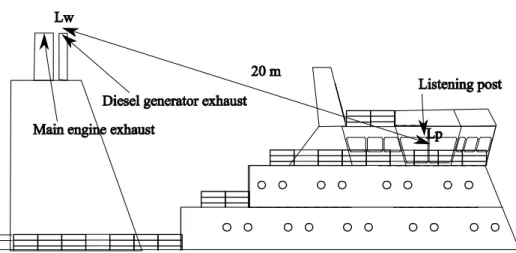
Consider a container ship equipped with one diesel generator and one main engine with exhaust outlets at 20 m distance from a listening post, see Figure 1.
Figure 1 Sound pressure level calculation at the listening post.
The noise limit at the listening post, as defined by IMO regulations, is 70 dB(A) at a normal sailing condition. This imposes limits on the maximum allowable sound power of the diesel generator and the main engine exhausts. The most basic propagation model describes the sound pressure level at a receiving position at a large distance from a noise source. The equation is shown below: 1 . ) 4 ( log 10 10 r2 Eq L Lp = w−
π
,Lp: Sound pressure level in the receiving position, dB re. 20µPa
Lw: Sound power level of source, dB re. 1pW
15
The above equation assumes spherical noise propagation in the free field i.e. that there are no reflections and attenuation is only due to spherical spreading with distance.
By applying the IMO noise limit and the above equation the maximum allowable total sound power of the main engine and diesel generator exhaust outlets can be calculated to 107 dB(A).
During berth only the diesel generator is in operation in order to generate electrical power onboard the ship. The main engine is stopped. The distances from the noise source that are required to fulfil the noise guiding limits in Table 1 can likewise be calculated by applying Eq.1.
As a worst case scenario a diesel generator exhaust sound power level of 107 dB(A) is adopted. This corresponds to the case where the diesel generator exhaust noise is considerably higher than the noise from the main engine.
The limits and calculated distances from the noise source in order to meet these limits are given in the table below:
Area type Monday -Friday 07-18 Saturday 07-14 Required minimum distance, m Monday-Friday 18-22 Saturday 14-22 Sunday+ Holy 07-22, Required minimum distance All days 22-07 Required minimum distance dB(A) m dB(A) m dB( A) m Industry area 70 20 70 20 70 20 Mixed residential and industry 55 110 45 350 40 630 Residential, City 50 200 45 350 40 630 Residential 45 350 40 630 35 1100 Recreational areas 40 630 35 1100 35 1100
Table 3 The approximated required distances, in calculation example 1, between the diesel generator and a receiver to fulfil the Danish Environmental Agency noise guiding limits. Reflections, absorption, screening effects etc. have been disregarded.
The distances from the ship required to fulfil the guiding limits are seen to be quite large especially if recreational areas are considered in the vicinity of the port berth.
The above calculation is radically simplified as a number of factors have not been taken into account. These are factors such as screening, reflection and absorption from buildings and surfaces, meteorological conditions, directivity of the noise sources, etc. A more accurate calculation of the noise caused by a ship in the surroundings can be performed by applying different standards for calculating the noise propagation such as the Danish environmental guideline no. 5/1993, [8]. Different standards and methods for calculating the
environmental noise from ships, industries etc. are included in different software tools such as ‘SoundPLAN’, ‘Predictor’ and ‘CadnaA’
It can be concluded that a ship in port that fulfils the IMO resolution can easily excess the Danish Environmental Agency guiding noise limits if at berth in the near vicinity of residential areas.
17
3
Noise sources
The primary sources of noise on a ship at berth that give rise to noise in the environment can be divided into three categories:
• Diesel generator engine exhaust
• Ventilation inlets/outlets
• Secondary noise sources, e.g. pumps, “reefer” refrigerated containers
The various noise sources are described in the following.
3.1 Diesel generator exhaust
The diesel generator is used to generate power on board the vessel. During port stay it will often be the most predominant source of noise radiating from the ship to the surroundings. The diesel engine exhaust is often placed at the top of a funnel which has a significant height compared to the surrounding landscape. The noise can therefore propagate over large distances without being reflected or absorbed by the surroundings. If the diesel generator
exhaust noise is not sufficiently attenuated with a well-designed silencer it may easily cause high noise levels in the surroundings, even at large distances. The unattenuated sound power level of the different diesel engine exhaust is in some cases supplied in the manufacturer’s engine project guide. An excerpt of the levels from project guides from two engine manufacturers is seen in the table below:
1/3-Octave frequency bands, Hz Make Type 16 31.5 63 125 250 500 1000 2000 400 0 8000 Tot al MAN B&W L32/40 80 V32/40 82 115 111 126 130 135 133 129 129 133 133 135 135 135 135 133 133 130 130 142 142 L48/60B 88 119 124 126 129 133 135 135 133 130 141 V48/60B 84 111 124 126 129 133 135 135 133 130 141 L58/64 80 115 130 135 129 133 135 135 133 130 142 Wärtsilä W26 - 122 132 135 131 125 124 118 112 102 138 W32 - 107 115 127 130 129 127 121 109 - 135 W38 - 101 119 122 127 131 134 129 126 118 138 Table 4 An excerpt of the unattenuated exhaust A-weighted sound power levels, dB(A) re. 1pW, provided in engine project guides by the engine manufacturers MAN B&W and Wärtsilä as found on their respective websites reference [9] and [10]. ‘L’ and ‘V’ in the type description indicate whether the cylinders are in line or placed in a
V-arrangement and the number indicates the diameter of the cylinder bore in centimetres.
The engine type number generally describes basic details, e.g. W6L32 is a 6 cylinder inline engine with a cylinder bore of 32cm. The data in Table 4 provides an idea concerning the magnitude of the unattenuated sound power of the exhausts of some of the commercially available diesel engines. The total sound power levels in the given selection of engines vary between 135dB(A) – 142dB(A) which is significantly higher than the maximum allowable sound power level of 107dB(A) found in calculation example 1. The silencer should,
18
in this case, attenuate the exhaust noise from the engine by approximately 28 - 35dB.
The frequency content of the exhaust noise from a given engine depends on a number of factors. The most important are the number of cylinders, the speed of the diesel engine and if it is a 2 or 4-stroke engine. The firing frequency of the engine, and multiples or harmonics hereof, depends on these factors and
can be determined by Eq.2.
,
2
.
....
4
,
3
,
2
,
1
,
·
60
·
·
Eq
p
p
a
n
z
f
p=
=
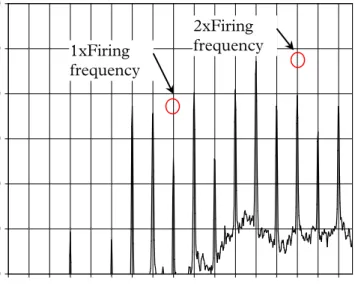
n=rotational speed (rpm) z=number of cylinders a=1 for 2-stroke engines a=2 for 4-stroke enginesIn many cases the component corresponding to twice the firing frequency is the most significant. However, it is usual to see frequency components corresponding to half and whole harmonics of the engine as well. As an example the 4-stroke Wärtsilä engine, W6L32, has a rotational speed of 720 rpm and 6 cylinders. Therefore the first harmonic of the engine rotational speed is 12 Hz and the firing frequency 36 Hz. A narrowband frequency sound pressure level measurement at 5 meters distance from the exhaust stack outlet of a W6L32 engine exhaust is shown in the figure below:
30 40 50 60 70 80 90 0 6 12 18 24 30 36 42 48 54 60 66 72 78 84 90 96 Frequency, Hz S ound pr e ss ur e l e ve l, d B A re . 1 ·10 ^ -6 Pa
Figure 2 Measured A-weighted sound pressure level, dB(A) re. 20 µPa, narrow-band frequency spectrum 0 – 100 Hz, at approximately 5 meters distance from a Wärtsilä W6L32 3000kW / 720 rpm engine exhaust stack outlet. An absorption type silencer is installed in the exhaust stack.
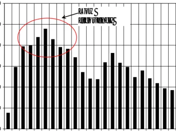
The narrowband frequency spectrum is seen to contain half multiples of the first harmonic. The component at twice the firing frequency is dominating the spectrum. The same measurement as shown in Figure 2 but analysed in 1/3-Octave bands, 25Hz – 4000Hz, is shown in Figure 3. The 1/3-1/3-Octave band measurement shows that the exhaust noise is mainly located in the frequency range 40 - 160Hz with the 80Hz-band dominating spectrum.
1xFiring frequency
2xFiring frequency
19
30 40 50 60 70 80 90 25 40 63 100 160 250 400 630 1000 1600 2500 4000 1/3 - Octave bands, Hz S ound pr e ss ur e l e ve l, d B A re . 1 ·10 ^ -6 PaFigure 3 Measured A-weighted sound pressure level, dB(A) re. 20 µPa, in 1/3-octave bands, at approximately 5 meters distance from a Wärtsilä W6L32 3000kW / 720 rpm engine exhaust stack outlet. An absorption type silencer is installed in the exhaust stack.
Because diesel generators are used to generate electrical power on board the ship the engines run at fixed speed. The AC-current generated onboard by the diesel generators is either 50Hz or 60Hz. Typical diesel generator engine speeds for a 60Hz current installation are:
7
...
3
,
2
,
60
·
60
=
=
n
n
Hz
s
rpm
I.e. 1800 rpm, 1200 rpm, 900 rpm, 720 rpm, 600 rpm and 514.3 rpm. As a rule thumb higher speed engines are used on smaller vessels and slower speed engines in larger vessels. The frequency content of the diesel generator exhaust is dependent on the engine speed as described earlier. Smaller vessels are likely to have higher frequency content and larger vessels lower frequency content in the exhaust noise spectrum.The actual sound power at the outlet of the exhaust stack with the silencer is dependent on a number of factors including the piping system layout, type, performance of the silencer and the location of the silencer in the exhaust stack.
3.2 Ventilation
Ventilation systems onboard ships may be a significant contributor to the noise generated by the ship in the surroundings if no noise reducing measures have been included in the design. Depending on the ship type different ventilation systems on board include engine room ventilation, cargo ventilation, AC-systems, galley ventilation, etc.
In some cases information on the sound power of the different fans is supplied by the manufacturers. An excerpt of the sound power levels of different engine room- and hold ventilation- fans as provided by a manufacturer are provided in the Table 5. The large hold ventilation fans are mainly used on RoRo ships for ventilating car decks. The sound power levels of the larger fans are seen to be quite significant.
Low frequency
20
1/3-Octave frequency bands, Hz Volume flow, m3/h 63 125 250 500 1000 2000 400 0 8000 Tot al Engine room fans 120000 73 93 98 105 105 102 98 91 110 70000 68 84 100 104 106 103 99 93 110 50000 66 82 98 101 103 101 97 90 108 33000 64 79 96 99 101 99 94 88 106 15000 51 67 80 95 96 96 92 86 101 12000 52 68 81 96 96 96 93 87 102 1000 39 55 73 78 83 83 80 74 88 1000 31 47 60 75 75 75 72 66 81 Hold ventilation 95000 75 93 97 100 100 97 91 83 105 85000 69 89 94 101 101 98 94 87 106 73000 67 83 99 102 104 102 97 91 109 Table 5 The A-weighted sound power, dB(A) re. 1pW, of different engine room and hold ventilation fans as supplied by a manufacturer.
The frequency content of the sound power of the fans in Table 5 is seen mainly in the intermediate frequency range, ca. 250 to 2000 Hz.
Noise from different ventilators and noise mitigating measures is well
described by Stampe in reference [19]. The sound power level of fans can be determined, with relatively good accuracy, based on empirical formulas which are also provided in [19]. Among these are:
3
.
),
(
10
log
20
)
(
10
log
10
*Eq
p
q
L
L
W=
W+
V+
∆
t qV = volume flow, m 3/s∆pt= fan total pressure difference, Pa
*
W
L
=specific sound power levelIn Eq.3 it is presupposed that the fan is operated at the designed maximum efficiency of the fan. The specific sound power level of the fan is dependant on the type. For radial ventilators it is 30dB and for axial ventilators 25-35dB. The ventilators in Table 5 are of the axial type. Eq.3 shows that the sound power increases with the volume flow and the fan total pressure difference. If the fan is not operated at the designed maximum efficiency the sound power of the fan will generally increase.
Without any noise reducing measures included in the ventilation system the sound power at the outlet/inlet ventilation grid will be comparable to the sound power of the fan.
3.3 Secondary noise sources
The normally dominating noise sources on board a ship at berth are the diesel generators and different ventilation systems. However, a number of secondary noise sources on the ship also contribute to the noise in the surrounding environment, for example different hydraulic pumps, loading/unloading of cargo, winches, reefer (Cooling containers). On container ships reefers are used for temperature controlled transportation. The sound powers of two reefers are provided in Table 6
21
1/3-Octave frequency bands, Hz
63 125 250 500 1000 2000 4000 8000 Total Note Reefer 69 79 80 81 81 78 73 65 87 measurements LR-ODS Reefer 66 78 82 84 84 84 78 69 90 Database Table 6 Typical A-weighted sound power, dB(A) re. 1pW, of Reefers. Measured by LR-ODS and data provided in [14].
The sound power of the reefers is approximately 90 dB(A). Compared to the sound power levels of the diesel generators and the ventilation it is
significantly lower. However, the total sound power will increase with the number of reefers approximately with:
...
3
,
2
,
1
),
(
log
10
10=
=
∆
L
n
n
n = the number of reefers
The total sound power of all the reefers onboard the ship can therefore be significant. If the ship is powered by on-shore power the reefers are likely to define the lower background noise limit of the container ship.
3.4 Environmental noise from ships in general
A relation between the dead weight tonnage, DWT, and the sound power level of ships has been sought to be established in [12], see Figure 4. The reported relation is based on measurements on 65 ships. The trend is that the sound power of the ship increases with the DWT. The diesel generators on smaller ships are often high speed engines with higher frequency content in the noise. Conventional exhaust silencers are often of the absorptive type with the most attenuation in the higher frequency range. Therefore, it may be speculated that the noise from the diesel engine exhaust noise on smaller ships is attenuated better than the exhaust noise on larger ships. Furthermore, the required ventilation in the engine room is less on smaller vessels, i.e. the engine room fans are smaller and have a lower sound power. However, the trend plot provided in Figure 4 also shows that there are large deviations of more than 20dB in the measured sound power on ships with the same DWT. A similar comparison of the sound power as a function of lane length has been performed for RoRo-ships, [13]. No relation between the lane length and sound power was found. The reported source power of the RoRo-ships varies between approximately 108 – 125 dB(A).
22
Figure 4 The relation between Dead Weight Tonnage and Sound Power Level established in [12].
In conclusion it is highly recommended that before estimating the sound power of a ship via the trend shown in Figure 4 that the individual noise sources and the noise reducing measures on the ship should be carefully evaluated.
23
4
Possibilities for noise reduction
4.1 Diesel generator exhaust
4.1.1 Silencers
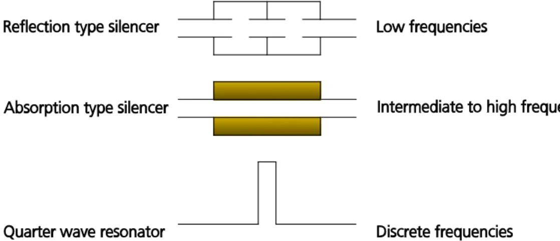
On the majority of larger ships silencers should be included in the exhaust stack of the diesel engines to fulfil the external IMO noise limits. The needed noise attenuation of a silencer should be determined by thorough calculations taking the type of engine, design of the exhaust stack, external noise limits and other relevant factors into consideration. In Figure 5 three different types of silencers are shown:
Figure 5 Different silencer principles applicable for reducing engine exhaust noise.
Conventional engine exhaust silencers are of the reflection type, absorption type or a combination of these two. The reflection type silencer is used for attenuating low frequencies. The absorption type attenuates the intermediate to the higher frequencies. The complete frequency range can be attenuated by a combination of the two.
0 5 10 15 20 25 30 35 63 125 250 500 1000 2000 4000 8000 1/1-Octave bands, Hz E xpe ct e d noi se a tt e nua ti on, dB Absorption type Reflection type
Figure 6 Examples of the expected noise attenuation in dB of an absorption type silencer and a reflection type silencer. The data is supplied by a silencer manufacturer.
24
In order to attenuate the very low frequencies the reflection type silencer should be sufficiently long. The magnitude of attenuation in the low
frequency region depends on the volume of the silencer. Space is often limited in the exhaust casing and therefore the silencer should be selected early in the design phase. The criteria for selecting the silencer should include which frequency range needs to be attenuated and how much the noise should be attenuated.
If noise problems are apparent after the exhaust stack has been installed it can be very cumbersome and expensive to solve because of space limitations in the casing. Depending on the specific noise problem e.g. low broadband frequency noise, a large reflection type silencer should be installed. A
structural modification on this scale should be carried out at a shipyard which is costly. The new silencer design should be carried out in close cooperation between the yard, engine manufacturer, silencer manufacturer and a noise consultant.
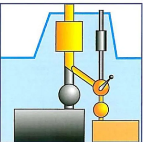
In special cases an exhaust noise problem can be solved with simpler means. Diesel generators run at fixed speed and the frequency content in the exhaust noise does not change. If a single tone is significant compared to the rest of frequency spectrum of the exhaust noise then a quarter-wave side branch or a Helmholtz resonator, which attenuate discrete frequencies, can be designed and installed in the exhaust stack. As an example a solution using a quarter wave resonator has previously been designed and successfully installed in the exhaust stack on the advice of Lloyd's Register ODS to solve a discrete frequency noise problem on a Danish fast ferry, [15]. A significant noise reduction of approximately 20 dB was achieved. As another example an unfortunate combination of a frequency component in the exhaust noise of an engine and the exhaust pipe length before and after the silencer can also cause significant pure tone problems, [11]. In this special case the noise may be reduced by changing the length of exhaust piping before or after the silencer. In addition to the conventional silencers a number of different engine exhaust silencers exist. The Helmholtz- and the quarter wave resonator attenuation principle are used in some of silencer designs. These silencers consist of several Helmholtz-resonators with different volume and quarter wave resonators with different lengths, see the figure below:
Figure 7 A silencer as described in [16] with different size of resonators.
As a result of the multiple resonators many discrete frequencies are attenuated and the silencer attenuates over a broader frequency region. The main
advantage of this type of silencer is the broadband low frequency attenuation combined with a low pressure loss. If the pressure loss of a complete exhaust stack is too high the diesel engine does not function properly. An advantage is therefore that it is possible to post-install this type of silencer without
increasing the total pressure loss of the exhaust stack too much. However, the installation should be performed at a shipyard. The silencers are described in e.g. [16] and [17].
25
4.1.2 Example
A cruise vessel faced the problem of excessive harbour noise when the vessel was planned to have regular calling at Stockholm Port. The noise level from the auxiliary exhaust was too high, and the harbour authorities rejected the application from the owner of the vessel. Furthermore, using a less noise sensitive location out of the town centre was not attractive to the cruise operator. The operating conditions and the design of the ship were studied. Initially, conventional solutions were considered, i.e. redesigned auxiliary engine exhaust systems with significantly improved silencers. However, space limitations and limited time available for modifying the systems meant that a conventional solution was difficult to find.
Finally, an elegant solution was found by Lloyd's Register ODS: because the main engines were out of operation in the port condition, it was possible by means of valves to redirect the auxiliary exhaust gas flow, and utilize the main engine exhaust silencers for the auxiliary engines. Modification of the pipe routing of the auxiliary engine exhaust was uncomplicated, since only the introduction of an extra valve and limited additional pipe work were required. The achieved noise attenuation was significantly high so the cruise vessel could easily get the environmental permission.
Figure 8 Rerouting of the diesel generator exhaust by utilising the main engine silencer during berth.
4.1.3 On shore power
Onshore power supply for the vessels during berth is another option that eliminates the need for power generation onboard. The noise from the diesel generator is thereby eliminated and the need for engine room ventilation is reduced. Engine room ventilation noise is therefore also expected to decrease. According to [20] ports are not normally prepared for supplying power to vessels and many vessels are not prepared for onshore power supply. Shore power has been established in a number of ports e.g. Göteborg, Helsingborg, Stockholm and Helsinki.
There may be technical difficulties in establishing on shore power and there are no standard for the power used on board ships i.e. voltage and frequency, but standardization is in progress. Ships that are obvious to consider for on shore power supply are ships frequently calling ports (such as ferries), with long port stays (such as bulk carriers), with high noise levels or with tonal content in the noise. Establishing on shore power is considered as a large investment. The noise reduction potential is however significant.
26
4.1.4 Calculation example 2: Reducing noise from the engine room ventilation
A 144m tanker is at port. A single diesel generator and the engine room ventilation are in operation. No noise reducing measures have been included in the engine room ventilation system. Silencers have been included in the diesel generator exhaust stacks. Hence, during normal sailing operation the ship fulfils the IMO noise limit at the listening post of 70dB(A).
A model of the ship including the noise sources has been implemented in the
environmental noise calculation software SoundPLAN, see Figure 9. It is
assumed that the sound propagates over a flat hard reflective ground. The sound power levels of the ventilation and the diesel generator are shown in the table below:
1/3-Octave frequency bands, Hz
31.5 63 125 250 500 1000 2000 4000 8000 Total Diesel generator exhaust 94 98 95 89 83 82 82 80 73 101
Engine room ventilation - 52 68 81 96 96 96 93 87 102 Table 7 The A-weighted sound power, dB(A) re. 1pW, of the diesel generator exhaust and the engine room ventilation before mineral wool is installed in engine room ventilation fan room.
Figure 9. Tanker without / with noise reducing measure in the engine room ventilation system.
The noise maps in Figure 9 shows that the noise at the portside of the ship to a
large extend is influenced by the engine room ventilation. In order to decrease the noise, mineral wool is installed in the fan room. As a result the noise decreases dramatically with up to 10dB. The external noise after the modification is mainly influenced by the diesel generator exhaust.
Diesel generator exhaust
Engine room ventilation
27
4.2 Ventilation
4.2.1 Standard silencers
Noise reducing measures for ventilation systems are less costly compared to decreasing noise from diesel generators.
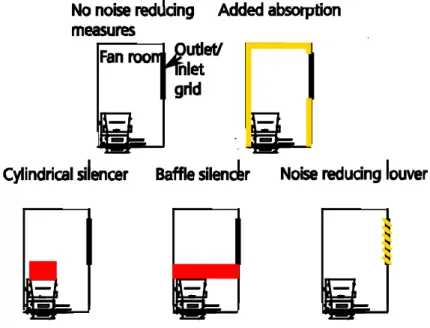
Various ways of attenuating noise from different ventilation systems exists.
Figure 10 shows a hold ventilation fan room with some of the different
possibilities for attenuating the noise from the ventilation fan.
The most inexpensive way of reducing ventilation noise is to install mineral wool in the fan room or the ventilation ducts. The mineral wool increases the sound absorption in the room and in the ducts. The mineral wool is normally covered with thin perforated steel plates, glass cloth or similar. The covering should be porous. Depending on installation details and properties of the mineral wool 10-15dB noise reduction can at best be achieved, [18].
Figure 10 Principle sketch of different noise reducing measures to decrease the noise at a ventilation intake/outlet.
The fan noise can also be attenuated with silencers. Many of the silencers are based on the noise absorption principle. These silencers include circular silencers, baffle silencers and noise reducing louvers.
Figure 11 The principle of baffle silencers and cylindrical silencers
The noise attenuation of absorption silencers is proportional to the ratio between the circumference of the acoustic material and the free flow area. The more the flow is restricted the higher the attenuation. The noise attenuation increases with increasing baffle and cylindrical silencer length. The drawback of increasing the attenuation is that the free flow is restricted
28
i.e. the pressure loss of the silencers increases and a too high restricted flow may cause additional flow noise. The restricted flow should not exceed approximately 15 m/s. It is difficult to attenuate lower frequencies i.e. 63Hz and 125Hz with absorption silencers. The attenuation in these bands can however be increased by increasing the width of the baffles or installing an absorption core in the cylindrical silencer.
4.3 Secondary noise sources
In some cases secondary noise sources such as compressors, pumps etc. can be a significant contributor to the noise emitted from the ship to the
surroundings. Different solutions for decreasing the noise exist depending on the specific noise problem. E.g. if a pump is rigidly mounted on a ship the large ship-structure helps radiating the structure-borne noise introduced by the pump. By resiliently mounting the pump the acoustic coupling between the pump and the ship-structure is minimised and the noise caused by the pump is reduced. If the problem is mainly airborne from the external machinery an acoustic enclosure can be engineered.
4.4 Other noise reducing measures
The noise emitted from a ship is in some cases asymmetric, similar to the case
shown in Figure 9. The ship can therefore advantageously be berthed with the
less noisy side facing the noise sensitive areas in the harbour. Another similar option is to require that ships provide data on measurements of the noise radiated to the surrounding before calling at a port. In this way the noisiest ships can be berthed furthest away from residential and noise sensitive areas. This could further be implemented by using an economical incentive for reducing the external noise from the ships. E.g., ships calling at a port without information on the noise emitted to the surroundings, or with high noise source levels, could be charged with an increased fee for berthing.
Another option is to enter a dialogue with the ships in order to explore if the operational time of different ventilation systems and other machinery could be decreased.
In some container terminals it may also be possible to rearrange containers and similar moveable equipment to screen noise sensitive areas from the ships.
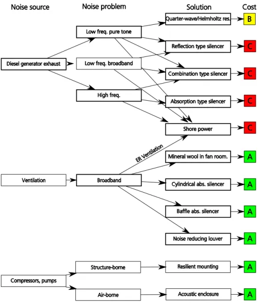
4.5 Summary – noise reduction
Figure 12 shows a diagram of different solutions to different external noise
problems and a ranking of the cost of the solutions. The diagram is based on the major sources of external noise on board a ship during port stay. Each of the solutions is assigned with a colour a letter defining the approximated cost. Red colour and the letter C indicates that the implementation of the solution is evaluated as being cumbersome, time-consuming and expensive. Yellow colour and the letter B indicates that the cost of the solution is estimated to be in the intermediate range i.e. that the solution can be implemented with less structural changes to the ship, that it is less time-consuming and is less expensive. Green colour and the letter A indicate that the solution is the least cumbersome to implement, the least time-consuming and estimated as the least costly of the presented solutions. Reducing noise from diesel generators will often require major structural changes to the ship e.g. installing new silencers. Structural changes of this magnitude are performed at a shipyard which is considered costly. Whereas, installing mineral wool in a fan room is simple and can be carried out by the ship’s crew or a contractor during port stay. A noise reducing measure on this scale is therefore considered less costly.
29
Figure 12 Diagram of different solutions to different external noise problems and the approximated cost of the solutions. Red colour and the letter C indicates estimated highest cost, yellow colour and the letter B indicates estimated less cost and green colour and the letter A indicates estimated least cost.
31
5 References
[1] Breemen, Ton Van, NoMEPorts, “Good Practice Guide on Port Area
Noise Mapping and Management”
[2] IMO Resolution A.468 (XII), ”Code on noise levels on board ships”,
1981
[3] IMO Resolution A.343(IX), “Recommendation on methods of
measuring noise levels at listening posts”, 1975.
[4] Danish Maritime Authority, Technical Regulation on Noise in Ships,
Technical Regulation no. 4, 3 May 2002
[5] Vejledning fra miljøstyrelsen nr.5/1984, ”Ekstern støj fra
virksomheder”.
[6] Vejledning fra miljøstyrelsen nr.9/1997, ”Lavfrekvent støj, infralyd og
vibrationer i ekstern miljø”.
[7] Arbejdsrapport fra Miljøstyrelsen nr. 45/1997, ”Vurdering af
lavfrekvent støj fra færger”.
[8] Vejledning fra miljøstyrelsen nr. 5/1993, ”Beregning af støj fra
virksomheder”
[9]
[10]
[11] Vellekoop, J.C, ”Exhaust silencers for diesel engines Part 2 Design
considerations and examples”, Technisch physische dienst, Internal Report No. 802/4
[12] Witte, R, “Container Terminals and Noise”, Internoise 2008.
[13] Witte, R, “Noise emissions RoRo terminals”, Euronoise 2009
[14]
HARMONOISE and IMAGINE research projects.
[15] Ødegaard, J., Nielsen, O.W. and Gosling A., “External Noise From
Fast Ferries”, Proceedings of FAST 97’
[16]
[17] Tae-Kyoung Lee, Won-Ho Joo and Jong-Gug Bae, “Exhaust Noise
Control of Diesel Engine using Hybrid Silencer”, Internoise 2008.
[18] Berg, Bråfelt, Folkeson, Støj og vibrationer om bord, Søfartens
Arbejdsmiljøråd, 1997.
[19] Stampe, Ole B., Lyd i VVS-anlæg, Skarland Press AS, 1998.
[20] Susann Dutt, Guidance document – Onshore Power Supply, C40
32
![Figure 4 The relation between Dead Weight Tonnage and Sound Power Level established in [12]](https://thumb-us.123doks.com/thumbv2/123dok_us/1972979.2792598/22.893.319.748.88.351/figure-relation-weight-tonnage-sound-power-level-established.webp)
![Figure 7 A silencer as described in [16] with different size of resonators.](https://thumb-us.123doks.com/thumbv2/123dok_us/1972979.2792598/24.893.309.752.749.875/figure-silencer-described-different-size-resonators.webp)