Air Force Institute of Technology
AFIT Scholar
Theses and Dissertations Student Graduate Works
3-14-2014
Programmable Logic Controller Modification
Attacks for Use in Detection Analysis
Carl D. Schuett
Follow this and additional works at:https://scholar.afit.edu/etd
This Thesis is brought to you for free and open access by the Student Graduate Works at AFIT Scholar. It has been accepted for inclusion in Theses and Dissertations by an authorized administrator of AFIT Scholar. For more information, please [email protected].
Recommended Citation
Schuett, Carl D., "Programmable Logic Controller Modification Attacks for Use in Detection Analysis" (2014).Theses and Dissertations. 622.
PROGRAMMABLE LOGIC CONTROLLER MODIFICATION ATTACKS FOR USE IN DETECTION ANALYSIS
THESIS
Carl D. Schuett, Master Sergeant, USAF AFIT-ENG-14-M-66
DEPARTMENT OF THE AIR FORCE AIR UNIVERSITY
AIR FORCE INSTITUTE OF TECHNOLOGY
Wright-Patterson Air Force Base, OhioDISTRIBUTION STATEMENT A:
The views expressed in this thesis are those of the author and do not reflect the official policy or position of the United States Air Force, the Department of Defense, or the United States Government.
This material is declared a work of the U.S. Government and is not subject to copyright protection in the United States.
AFIT-ENG-14-M-66
PROGRAMMABLE LOGIC CONTROLLER MODIFICATION ATTACKS FOR USE IN DETECTION ANALYSIS
THESIS
Presented to the Faculty
Department of Electrical and Computer Engineering Graduate School of Engineering and Management
Air Force Institute of Technology Air University
Air Education and Training Command in Partial Fulfillment of the Requirements for the Degree of Master of Science in Cyber Operations
Carl D. Schuett, B.S. Master Sergeant, USAF
March 2014
DISTRIBUTION STATEMENT A:
AFIT-ENG-14-M-66
PROGRAMMABLE LOGIC CONTROLLER MODIFICATION ATTACKS FOR USE IN DETECTION ANALYSIS
Carl D. Schuett, B.S. Master Sergeant, USAF
Approved:
//signed//
Maj Jonathan W. Butts , PhD (Chairman)
//signed//
Maj Thomas E. Dube, PhD (Member)
//signed//
Mr. Stephen J. Dunlap, MS (Member)
20 Feb 2014 Date 20 Feb 2014 Date 20 Feb 2014 Date
AFIT-ENG-14-M-66
Abstract
Unprotected Supervisory Control and Data Acquisition (SCADA) systems offer promising targets to potential attackers. Field devices, such as Programmable Logic Controllers (PLCs), are of particular concern as they directly control and monitor physical industrial processes. Although attacks targeting SCADA systems have increased, there has been little work exploring the vulnerabilities associated with exploitation of field devices. As attacks increase in sophistication, it is reasonable to expect targeted exploitation of field device firmware.
This thesis examines the feasibility of modifying PLC firmware to execute a remotely triggered attack. Such a modification is referred to as a repackaging attack. A general method is used to reverse engineer the firmware to determine its structure. Once understood, the firmware is modified to add an exploitable feature that can remotely disable the PLC. The attacks utilize a variety of triggers and take advantage of already existing functions to exploit the PLC. Notable areas of the firmware are described to demonstrate how they can be used in attack development. The performance of the repackaged firmwares are compared to known unmodified firmwares to determine if the modifications negatively impact performance. Findings demonstrate that repackaging attacks targeting PLCs are feasible and that the repackaged firmware does not impact the PLC’s ability to execute programmed tasks. Finally, design recommendations are suggested to help mitigate potential weaknesses in future firmware development.
Acknowledgments
I would like to thank Maj Butts for your hard work and support in helping me to complete this work. I would also like to thank Steve Dunlap for your help and valuable technical expertise. I would also like to thank my fellow students who have provided support to me over my time here.
Table of Contents
Page
Abstract . . . iv
Dedication . . . v
Acknowledgments . . . vi
Table of Contents . . . vii
List of Figures . . . x
List of Tables . . . xii
List of Acronyms . . . xiii
I. Introduction . . . 1 1.1 Background . . . 1 1.2 Motivation . . . 2 1.2.1 Research Questions . . . 3 1.3 Research Contributions . . . 4 1.4 Limitations . . . 4 1.5 Methodology Summary . . . 6 1.6 Thesis Overview . . . 6 II. Background . . . 7 2.1 Overview of SCADA . . . 7 2.1.1 SCADA Characteristics . . . 7 2.1.2 SCADA History . . . 10
2.2 Security Issues Associated with SCADA Networks . . . 11
2.3 Emedded Device Security . . . 14
2.4 PLC Security Research . . . 17
2.5 Embedded Device Attacks . . . 21
2.6 Reverse Engineering Research . . . 23
Page
III. Methodology . . . 26
3.1 Problem Definition . . . 26
3.1.1 Goals and Hypothesis . . . 26
3.1.2 Approach . . . 27
3.2 Environment . . . 30
3.2.1 Programmable Logic Controller (PLC) and Firmware Specifications 30 3.2.2 Deployment Tools . . . 30
3.2.3 Firmware Analysis Tools . . . 31
3.2.4 Assembly Development Tools . . . 31
3.2.5 Performance Analysis Tools . . . 32
3.3 Reverse Engineering Effort . . . 33
3.3.1 Hardware Analysis . . . 33
3.3.2 Firmware Analysis . . . 34
3.4 Attack Development . . . 35
3.4.1 Assembly and Firmware Modification . . . 35
3.4.2 Deployment and Evaluation . . . 36
3.5 Performance Analysis . . . 41
3.5.1 Workload . . . 41
3.5.2 Data Collection Environment and Process . . . 41
3.5.3 Analysis . . . 44
3.6 Methodology Summary . . . 44
IV. Results . . . 46
4.1 Reverse Engineering Results . . . 46
4.1.1 Hardware Analysis Results . . . 46
4.1.2 Firmware Analysis . . . 47
4.1.2.1 Static Analysis . . . 47
4.1.2.2 Dynamic Analysis . . . 51
4.1.3 Identified Firmware Sections . . . 51
4.1.3.1 Diagnostic Test . . . 51
4.1.3.2 Processor Mode Diagnostics . . . 51
4.1.3.3 CIP Object Class Manager . . . 53
4.1.3.4 Non-Volatile Storage . . . 56
4.1.3.5 Additional Notable Areas . . . 60
4.2 Attack Development . . . 63
4.2.1 Redirecting Execution . . . 65
4.2.2 Time Based Non-Persistent Denial-of-Service Attack . . . 65
4.2.3 Mode Change Based Non-Persistent Denial-of-Service Attack . . . 66
4.2.4 Common Industrial Protocol (CIP) Based Non-Persistent Denial-of-Service Attack . . . 69
Page
4.2.5 CIP Based Persistent Denial-of-Service Attack . . . 70
4.2.6 Attack Evaluation Results . . . 72
4.2.6.1 Time Based Non-Persistent Denial-of-Service (DoS) Attack Evaluation Results . . . 73
4.2.6.2 Mode Change Based Non-Persistent DoS Attack Evalu-ation Results . . . 74
4.2.6.3 CIP Based Non-Persistent DoS Attack Evaluation Results 75 4.2.6.4 CIP Based Persistent DoS Attack Evaluation Results . . . 76
4.3 Performance Analysis Results . . . 78
4.4 Results Summary . . . 80
V. Conclusions and Future Work . . . 82
5.1 Conclusions . . . 82
5.2 Recommendations . . . 82
5.3 Impact . . . 83
5.4 Future Work . . . 84
5.4.1 Common Firmware Design Features . . . 84
5.4.2 Performance Analysis . . . 84
5.4.3 Data Corruption or Modification . . . 85
5.4.4 Persistence and Propagation . . . 85
5.4.5 Extortion . . . 85
5.5 Summary . . . 85
Appendix A: Jump Calculation IDA Pro Script . . . 87
Appendix B: Python Scripts . . . 90
Appendix C: R Scripts . . . 95
List of Figures
Figure Page
2.1 Logical SCADA Layout. . . 7
2.2 Example PLC Chassis Layout [43]. . . 9
2.3 IC Defensive Monitor Example [2]. . . 16
2.4 External Verification Passive Tap [32]. . . 19
3.1 Development Process Outline. . . 27
3.2 PLC Device Hierarchy. . . 28
3.3 JTAG Interface. . . 32
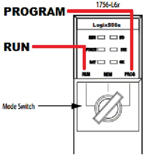
3.4 Front Panel Mode Change Switch. . . 39
3.5 Experiment Equipment Configuration. . . 43
4.1 Firmware Image Header Structure. . . 49
4.2 Diagnostic Routine Return Codes. . . 52
4.3 REMOTE RUN Mode Change Condition. . . 53
4.4 Service Code Tests incmconmgr. . . 54
4.5 Class Handler Call to Connection Manager. . . 55
4.6 Connection Manager Object Class Test. . . 55
4.7 Test For Identity Object Class. . . 56
4.8 Case 1 - Service 0x1 Instance 0x1. . . 56
4.9 Case 2 - Service 0x3 Instance 0x2. . . 57
4.10 Case 3 - Service 0x4 Instance 0x6. . . 57
4.11 Test Start and End Arguments for Valid Range. . . 58
4.12 Setup Flash Block Erase Control Signals. . . 58
4.13 Setting Block Erase Command Code Values and Sending to Flash Memory. . . 59
Figure Page
4.15 Test for Active Monitor. . . 61
4.16 Calls to Fault Handler. . . 61
4.17 Start of Fault Handling Jump Table. . . 62
4.18 CPU Mode Test Function. . . 63
4.19 CPU Mode Test Function. . . 64
4.20 Modified Diagnostic Routine. . . 64
4.21 Branch Instruction Structure. . . 66
4.22 Process Flow - Time Based Non-Persistent DoS Attack. . . 67
4.23 Function Hook for Time Based Non-Persistent DoS Attack. . . 67
4.24 Function Hook for the Mode Change Based Non-Persistent DoS Attack. . . 68
4.25 Process Flow - Mode Based Non-Persistent DoS Attack. . . 68
4.26 Process Flow - CIP Based Non-Persistent DoS Attack. . . 69
4.27 CIP Function Hook - CIP Based Non-Persistent DoS Attack. . . 70
4.28 cpmodeFunction Hook - CIP Based Non-Persistent DoS Attack. . . 71
4.29 Call to Flash Write Function - CIP Based Persistent DoS Attack. . . 71
List of Tables
Table Page
4.1 Mode Setting Register Values. . . 53
4.2 Time Based Non-Persistent DoS Attack Evaluation. . . 74
4.3 Mode Change Based Non-Persistent DoS Attack Evaluation Results. . . 75
4.4 CIP Based Non-Persistent DoS Attack Evaluation. . . 76
4.5 CIP Based Non-Persistent DoS Attack Evaluation. . . 78
List of Acronyms
Acronym Definition
CIP Common Industrial Protocol CPU Central Processing Unit CRC Cyclic Redundancy Check DNP3 Distributed Network Protocol v3 DoS Denial-of-Service
HMI Human Machine Interface IC Integrated Circuit
ICS Industrial Control System IDS Intrusion Detection System IP Internet Protocol
IT Information Technology JTAG Joint Test Action Group LAN Local Area Network
PLC Programmable Logic Controller
SCADA Supervisory Control and Data Acquisition WAN Wide Area Network
PROGRAMMABLE LOGIC CONTROLLER MODIFICATION ATTACKS FOR USE IN DETECTION ANALYSIS
I. Introduction
1.1 Background
Supervisory Control and Data Acquisition (SCADA) systems monitor and remotely control critical industrial processes, such as gas pipelines, electric power transmission, and potable water distribution/delivery [50]. In recent years, attacks targeting SCADA systems have significantly increased [53]. Indeed, aging equipment, unique hardware, limited processing capabilities, and distance are factors that hamper the ability to implement a low cost or viable solution for protection [25].
To date, attacks on SCADA systems have primarily focused on the high-level systems (e.g., human machine interfaces) or network protocols (e.g., Ethernet or MODBUS) [40]. Even Stuxnet, considered one of the most sophisticated cyber attacks [22], exploited high-level application software and did not directly exploit the low-level field device firmware code [15]. Indeed, little research has been accomplished that directly investigates the exploitation of field device firmware code [8].
This research focuses primarily on field devices, specifically on field devices known as Programmable Logic Controllers (PLCs). PLCs collect data and interact with sensors, motors, valves, and other devices throughout an industrial complex for streamlined management and automation control [10]. By assuming control of the PLC, an attacker can directly affect the outcome of, or interfere with, the underlying industrial processes. As attacks increase in sophistication, it is likely that attackers will target PLC firmware for exploitation; such attacks could have devastating consequences. The goal
of this research is to determine the feasibility of developing firmware-based attacks that specifically target the PLC. The attacks are intended to demonstrate the ability to disable PLC functionality while remaining undetected. Once attack capabilities are understood, solutions and strategies can be developed to mitigate the threats.
1.2 Motivation
The PLC remains a weak spot in industrial control security. For a variety of reasons, companies are increasingly automating industrial systems. They are also exposing these industrial systems to external networks in order to facilitate remote administration or to save money by using existing communication links to maintain contact with remote end points [54]. These actions have the unintended side-effect of increasing the attack profile of SCADA networks. Ethernet modules used in conjunction with PLCs often host web servers used for remote administration [40]. The PLC and PLC support modules were designed for high availability, not security, exposing the PLC to the threat of attack [12].
The PLC directly interfaces with devices that control or measure industrial control processes. A compromised PLC provides an attacker with direct access to data collected by the sensors as well as actuators controlled by the PLC. This direct access provides the ability to cause physical damage as seen in Project Aurora [34]. Exploiting such weaknesses in a controlled manner highlights the need for improved industrial control security and secure design strategies.
This research examines the feasibility of developing firmware based attacks that specifically target the PLC. This research hypothesizes that an attacker is capable of crafting an attack that disables/destroys the PLC. The attack must execute when signaled using a pre-determined command, and otherwise remain dormant in the firmware.
The PLC is a purpose built computer designed specifically to operate industrial control systems. The PLC is divided into three layers. The hardware layer contains the physical components of the device including memory, processors, and interfaces needed
to communicate with other components. The firmware layer acts as the operating system of the PLC. Firmware provides services such as hardware and software monitors as well as executing process control programs [11]. The programming layer contains the process control program executed by the firmware. Firmware provides the control capability while the process control programs provide specific instructions on how to handle process inputs and outputs. The firmware is the primary focus of this research. A firmware based attack is used because such an attack would function regardless of the task the PLC performs and does not rely on exploiting a specific process control program.
1.2.1 Research Questions.
PLC firmware updates are provided by the manufacturer to add features, correct bugs, or improve performance. The update process provides a vector for attacking the PLC. Firmware images can be captured and modified to insert malicious instructions. The firmware image is then repackaged to appear as a legitimate update to the PLC. Such an attack is referred to as a repackaging attack [27]. Reverse engineering the firmware offers a path to success for executing the repackaging attack. In order to successfully reverse engineer and modify the firmware, several sub-goals must be met.
1. Map firmware instructions to device functions.
In order to integrate the attack into the existing firmware image, it is necessary to identify function calls that execute under known conditions. Such functions provide the necessary triggers to execute the attack. The integrated attack may also call existing functions in the firmware image. Such calls may contribute to the attack by altering memory or sending the PLC into a fault state. The PLC is not designed for interactivity and contains no terminal interface that could be used for feedback during the reversing process [46]. However, the device contains a debugging interface that can be used to trace program execution and step through instructions.
2. Maintain device stability with added instructions.
A possible goal of an attacker may be the destruction of the PLC through the use of maliciously modified firmware [40]. However, it may not be the intention of the attacker to immediately execute the attack, but rather to implement the attack as a trojan horse and execute at a later time. Since the attack is not executed immediately, it must remain undetected until used. An associated challenge is injecting instructions into the firmware without altering or overwriting functions that are necessary for the PLC to function. The modified firmware must remain stable and maintain timing performance [20]. Stability and performance evaluation standards are defined in Chapter III.
3. Bypass device verification checks.
The PLC contains verification tests that must be bypassed in order to force the PLC to accept the modified firmware as a legitimate copy. Basnightet al.developed methods for modifying the checksum and Cyclic Redundancy Check (CRC) used as a verification test on the Allen-Bradley Controllogix 1756-L61 PLC [8]. Basnight’s
et al.method is used to repackage the firmware image as a legitimate copy.
1.3 Research Contributions
This research serves primarily to develop secure design practices for protecting SCADA devices by highlighting the inherent weaknesses in the design of the PLC firmware. Furthermore, this research intends to demonstrate the feasibility of embedding attacks in repackaged firmware. The process used to develop repackaged firmware can provide insight into the methods attackers use to reverse engineer and exploit firmware.
1.4 Limitations
This experiment has several limitations and assumptions. The experiment uses Allen Bradley Controllogix 1756-L61 PLCs. The ControlLogix 1756-L61 PLC was
chosen because of its use in directly related previous research and for its widespread use in the industrial control sector [42]. The performance analysis used in this experiment was developed by Dunlap using Allen Bradley PLCs and is assumed to represent data collection capabilities available on other platforms [20].
PLC security is not turned on during the experiment. Note that PLC security is a feature of Allen Bradley PLCs that locks the Central Processing Unit (CPU) with a password. This feature is turned offby default when shipped by the manufacturer and the default security setting is rarely changed [40]. This research does not evaluate the effects of PLC security on the repackaged firmware.
The Controllogix 1756-L61 PLC is set to REMOTE mode for the duration of the experiment. This mode allows the device to be remotely managed to include both monitoring and updating tasks [45]. Physical access to the PLC is required to update either the firmware or programs if the PLC is moved out of REMOTE mode using the front panel mode switch.
The monitoring system is limited to program execution time comparisons only [20]. The Controllogix 1756-L61 PLC must meet program execution time specifications in order to satisfy system requirements [11]. The repackaged firmware can remain undetected if it does not adversely impact program execution times. Additionally, network traffic monitoring shown by research such as McMinnet al.has demonstrated effectiveness in detecting unauthorized changes to firmware images [33].
The Controllogix 1756-L61 PLC is assumed stable after eight hours of continuous operation without major fault using the repackaged firmware. No process program is executed during stability testing. This test is not exhaustive, and is assumed sufficient for the purpose of this proof-of-concept experiment. Furthermore, only the stability of the firmware is tested. While program execution times are important for measuring performance impacts, the correctness of program outputs are not tested.
1.5 Methodology Summary
The feasibility of modifying the firmware of a PLC is determined through the use of reverse engineering and assembly program development. The Controllogix 1756-L61 PLC must continue to operate without a major fault after the repackaged firmware is installed until the attack is executed. The attacks built in to the repackaged firmware are evaluated for correct functionality and stability using the evaluation criteria specified in Chapter III.
The attack is developed by acquiring the unmodified firmware and using reverse engineering tools to analyze the instructions and determine the internal structure. With knowledge of the internal structure, an attack is crafted to disable the device at the prompting of an external source. Such an attack is one of several proposed as possible attacks against embedded devices by Peck and Petersen [40].
Finally, program execution times are collected from the Controllogix 1756-L61 PLC using both the unmodified and repackaged firmware. The collected program execution times are compared to determine statistically significant impacts to performance caused by the repackaged firmware. The performance analysis method was developed by Dunlap to detect alterations to firmware images [20].
1.6 Thesis Overview
Chapter II discusses relevant works used to develop the reverse engineering plan in this experiment. Chapter III provides a detailed description of the methodology. Chapter IV presents the results of the reverse engineering experiment. Chapter V summarizes the thesis topic and recommends areas of future research.
II. Background
2.1 Overview of SCADA
SCADA systems provide a means to collect data and exert control over distributed industrial processes. SCADA provides the means for operators to monitor and control systems spread over a large geographic region from a central control point. Typically, SCADA is used in critical infrastructure such as municipal water delivery/treatment, oil and gas pipelines, or electrical power distribution [50].
2.1.1 SCADA Characteristics.
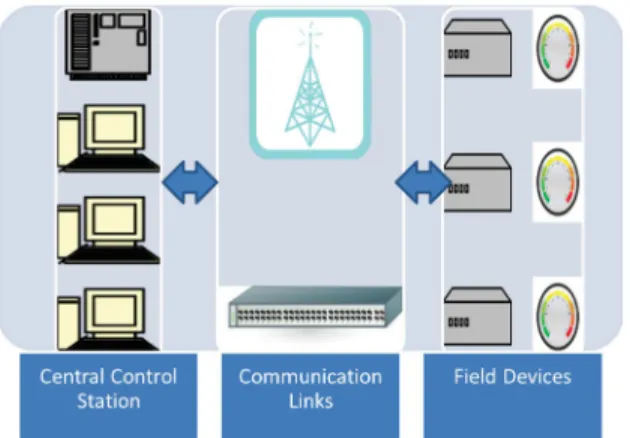
As shown in Figure 2.1, SCADA networks have three basic components: a central control station; field devices; and the communication links between the control station and the field devices [11].
Figure 2.1: Logical SCADA Layout.
The central control station typically contains an Human Machine Interface (HMI) that allows operators to interact with the SCADA network. Operators provide instructions to field devices and monitor the status of the network [11]. The HMI contains the bulk of the computing power in the SCADA network and can provide many of the services
needed by the system. The central control point monitors and controls the field devices and provides scheduling and logging using data gathered from remote nodes. The HMI manages and presents data collected throughout the network to the human operators [11].
The communication link between the control center and the field devices can be any medium capable of transmitting data as long as it satisfies the system requirements. The types of links used are often determined by the distance between stations, the physical barriers between those stations, or the existing communications links [11]. For instance, radio communications can be used to reach sites that are separated by rough or undeveloped terrain. Within a city it may be possible to utilize existing cell phone networks for communication. Links can consist of wireless radio, telephone, or increasingly Ethernet.
SCADA devices utilize different protocols to facilitate communication [55]. Some of the more widely-used protocols include the following.
• Distributed Network Protocol v3 (DNP3): This protocol was originally designed to provide an open standard for communication between SCADA devices [18]. DNP3 was designed specifically for the electrical utility industry but is also used in water and oil transportation. DNP3 was originally developed as a serial line protocol, but now supports Internet Protocol (IP) based communication as well.
• Modbus: This protocol is an open standard and the most widely used communica-tion standard for industrial systems [18]. Modbus supports both wired and wireless communications with extensive use in the oil and gas distribution and delivery in-dustry.
• FOUNDATION Fieldbus: This protocol is used extensively in process control [23]. It has two implementations: a low speed version for field devices, and a high
speed version specifically designed to operate with standard Ethernet based network devices such as routers and switches.
• Common Industrial Protocol (CIP): The Common Industrial Protocol is a media independent messaging protocol utilized in the industrial sector [49]. This protocol was designed to be scalable, used at every level of the automation process, and integrate easily into Ethernet based networks.
The field devices at the edge of the SCADA network contain embedded devices that control and monitor physical processes. The PLC is an example field device that contains programmable memory for the purpose of executing a sequence of instructions that collect data from attached sensors and transmit that data back to the operations center. The PLC can also translate instructions into actuator movement based on the input of the attached sensors (e.g., opening or closing a valve or changing the speed of a motor) [50]. A typical PLC configuration shown in Figure 2.2 consists of several interchangeable modules connected to a chassis and configured to control a process.
Basnightet al. describe the multilevel architecture of the PLC [8]. The three layers are the hardware, firmware, and a programmable layer. The intermediate firmware layer provides the interface between the hardware and the programmed instructions loaded by the engineer. All functions made available in the firmware must map to a hardware implementation [24]. In embedded devices, the firmware is considered the operating system [51]. Embedded devices such as PLCs use firmware as an operating system since the size and capacity of the device make it unnecessary to implement an additional software based operating system to operate on top of the firmware. Because of this design, firmware within SCADA devices can be full featured and offer a variety of services such as a web server for remote administration. Many SCADA devices also allow the firmware to be updated remotely. Note that these types of convenience features also provide possible attack vectors to potential adversaries.
2.1.2 SCADA History.
SCADA history can be categorized into three stages. In the earliest incarnation of SCADA networks, the mainframe was the center of the network. Technicians could monitor the status of the network through an HMI that was tied directly to the mainframe. On the remote end were the field devices and sensors recording information and relaying data to the mainframe. Telephone networks provided the communication links between the central mainframe and field devices. The networks were either leased from the local telephone provider or installed by the equipment owner. This centralized SCADA architecture began in the 1960’s and continued through the 1980’s [50].
Beginning in the 1980’s and continuing today, the next stage of SCADA networks employed a distributed architecture. Rather than risk failure on a single mainframe, work was divided among several systems that each performed a certain function. This implementation alleviated the risk of a single point of failure, and made redundancy easier [50].
Beginning in the 1990’s, SCADA networks evolved to incorporate traditional Information Technology (IT) methods and implemented client/server networks.
Controlling servers were implemented using a combination of special purpose equipment and commercial offthe shelf hardware. Communication between the central control point and remote sensors changed to Local Area Network (LAN) or Wide Area Network (WAN) technologies rather than telephone lines [50].
2.2 Security Issues Associated with SCADA Networks
There are several security challenges in the SCADA realm. These challenges stem from disparate requirements between industrial control systems and Internet networking technology. Between the three core principles of information assurance (i.e., confidentiality, integrity, and availability), SCADA networks are designed primarily for availability [28]. Internet technologies focus on integrity and confidentiality. Depending on the environment, a traditional corporate network can tolerate slow or lost network connectivity. A SCADA environment, however, has minimal tolerance for data loss or communication delay. The SCADA network is expected to be available for extended periods of time and to meet strict timing requirements [12].
Security in an industrial control system was traditionally implemented by physically isolating the SCADA network from the Internet or the corporate network. The need to reduce costs by eliminating redundancies, and the need to increase the speed with which information is available have motivated SCADA network engineers to adopt common networking technologies, exposing SCADA networks to the Internet [12]. The adoption of traditional networking protocols can reduce or eliminate redundant and expensive communication links such as leased telephone lines, however, their usage also exposes SCADA devices to the same attacks that more mature Internet enabled devices defend against by default.
In June of 2010, security researchers from VirusBlokAda discovered what would come to be known as the Stuxnet worm [15, 31]. This worm did not attack the PLC directly, but rather targeted the controlling HMI. Stuxnet was designed to destroy specific types of gas centrifuges, believed to be used in uranium enrichment for nuclear weapons by varying the speed of the controlling motors and operating the centrifuges outside of their accepted operational range.
As a result of Stuxnet, SCADA security awareness has gained increased exposure in the industrial control community [25]. Indeed, SCADA security is no longer treated as a theoretical problem, and vulnerability discovery has risen exponentially since 2010 [53]. However, SCADA security is often relegated to IT specialists who are often unfamiliar with the protocols and processes used in SCADA networks and are unable to adequately protect SCADA resources [12]. Additionally, the field devices of SCADA networks are typically low power and low capability sensors. These devices do not have the computing power or communication bandwidth to accommodate the additional overhead incurred by implementing security measures such as encryption or authentication. Should more secure hardware become available, replacement costs may deter adoption, with a single Controllogix 1756-L61 PLC costing approximately $6500.00 [41]. This replacement cost is multiplied in installations using multiple PLCs.
Dzunget al. point out that the long lifespan of SCADA field devices means that new devices added to the network will likely have to be backwards compatible with technology or protocols 10 or more years old [21]. This burden carries forward vulnerabilities associated with the older protocols. Additionally, Dzunget al.show significant security flaws in several areas of ICS networks. Wireless radio networks are susceptible to jamming and environmental interference. Power line communication systems are susceptible to eavesdropping because the power lines were not designed for
data transmission rates. Impedance mismatches and noisy communication medium cause significant signal leakage.
Igureet al. examine the general state of SCADA security and summarize many of the associated concerns [26]. SCADA networks are vulnerable to attack because SCADA devices are low capability, designed for performance rather than security, and utilize a large number of unique protocols that all must be protected equally. Yet despite the security weaknesses of SCADA devices, they are increasingly connected to the Internet without the benefit of the same types of protection that IT assets have had access to for years. Igureet al. point out that the lack of encryption on the typical SCADA network means that any attacker that gains access to the network can monitor traffic and learn the commands used to communicate between the operations center and the field devices [26].
Igureet al. outline three security challenges that must be addressed in SCADA networks [26]. First, improving access controls by eliminating or securing entry points into the network and using more robust authentication such as smart card access. A typical flaw in embedded systems is that the device password is often stored in non-volatile memory and in an unencrypted form [21]. Second, strengthening interior network security by implementing firewalls or Intrusion Detection System (IDS), implementing cryptography, and improving protocol security. There are few vendors, however, that include support for common SCADA protocols in their firewalls or IDSs [26]. Finally, when implementing effective security management, Igureet al.
stress the need to implement effective security policies, and a strategy that includes configuration management as well as security auditing and assessment to use as feedback for improvements.
2.3 Emedded Device Security
This section summarizes research focused specifically on the security of embedded devices. Note that not all research is specific to SCADA security. Regardless, the research emphasises the types of weaknesses found in embedded systems.
Dacostaet al. discuss their analysis of the firmware from a Cisco 7960G IP phone [17]. They highlight the vulnerabilities present in embedded devices. They performed both dynamic and static analysis of the firmware images used on the typical Cisco phone available in 2007. Dynamic analysis did not reveal any major vulnerability. However, static analysis showed that the firmware was built using a version of the C programming language. During analysis, the authors found instances of known unsafe functions such as strcpyormalloc[17]. These types of functions have been exploited in the use of buffer overflow attacks, and their use in C is strongly discouraged. Additionally, the authors found little to no memory protection, predictable stack layouts, and debugging functions that output messages about the state of the software to a telnet terminal. According to the authors, many of these issues have been addressed through patches, but this is just one example of an embedded system and weaknesses that are likely present throughout the sector.
McMinn highlights a critical component of embedded device security in Integrated Circuit (IC) supply chain management [32]. Manufacturers purchase general purpose ICs rather than design chips for specific needs. When integrating chips into a device, the chips are often tested only to ensure they are capable of successfully performing the needed functions rather than all possible functions. This type of testing leaves open the possibility of embedding functions into the IC that would allow an attacker to modify the behavior of the device at a later time [5]. This potential vulnerability has led to DARPA’s “Trust in IC’s” [16] and “Integrity and Reliability in Integrated Circuits” initiatives [36]. Both initiatives seek to create methods to determine if an IC contains malicious logic. There is
also a simultaneous effort to certify trusted vendors [52]. Such efforts help mitigate the risks in purchasing components from multiple vendors.
McFaddenet al.describe three types of supply chain attacks [30]. Circuitry
modification, programmable hardware attacks, and firmware attacks. Firmware provides the interface between device hardware and software and provides a vector of attack. Modified firmware can intercept requests for services from the device hardware or modify returned results to suit the needs of the attacker. Many embedded devices contain modifiable firmware which provides both a means of protection for the system owner and an additional means of attack. Flash programmable devices can be updated to close potential security holes, but also provide an attacker the means to upload malicious firmware to the device. The problem can be exacerbated in cases where the device requires no authentication to update the firmware.
Abramovici and Bradley propose incorporating defensive logic into ICs [2]. As seen in Figure 2.3, the logic passively captures signals among the various segments of the chip. The logic allows users to monitor the chip for abnormal behavior by checking for output signals from a device when it should be in a powered offstate or if the clock is disabled. Such logic could also be used to provide basic memory protection to identify attempts to address restricted or unused memory. Indeed, such a design may be effective in detecting possible attacks, or possible execution of trojan logic, and it provides a method to detect trojan logic in existing devices.
Duflotet al. discuss measures that can be used to detect a potentially compromised embedded device [19]. Their research focuses mainly on network interface cards, but the proposed solutions could be applied to other types of embedded devices that interact with a trusted agent such as a host responsible for distributing firmware updates. Duflotet al.
state that successful attacks have been developed for several types of embedded devices such as keyboard controllers, chipsets, and network interface cards. These are devices that
Figure 2.3: IC Defensive Monitor Example [2].
run with system privileges, and can be used to compromise the operating system of a host device. This same lesson can be applied to a PLC where a compromised module could be used to gain control of the device firmware.
Duflotet al. summarize two methods for monitoring an embedded device for possible compromise [19].
1. The first method is called Control Flow Integrity. This method states that a device must follow a predetermined control path based on the inputs to the device. The control path can be monitored through memory access control. If the firmware attempts to move to a memory location outside its area of control, then an alarm condition is raised. This method also uses a shadow stack, or a copy of the firmware’s stack maintained by a monitor, to verify that the actual stack matches
a pre-determined structure. An alarm is raised if a stack pointer attempts to redirect control flow to an unknown instruction.
2. The second method is Remote Firmware Attestation. This method computes a checksum from the contents of the memory of an embedded device. If the checksum matches predetermined good values, then the device is considered trusted. Duflotet al.acknowledge that this method can be defeated if an attacker maintains known valid copies of memory and uses those stored states to calculate a valid checksum. This challenge can be overcome by setting a time target for calculation [19]. To overcome this challenge, Abuhmedet al.propose calculating the checksum based on the entire memory space so that cached copies cannot be stored by an attacker. Note that calculating a checksum for the entire memory space imposes a performance penalty [4].
2.4 PLC Security Research
Mulderet al. analyze PLCs for weaknesses by looking at different segments of the device [37]. This includes performing hardware analysis, firmware analysis, and analyzing backplane communications. These three approaches provide complimentary clues about the structure of the device. In hardware analysis, individual components are catalogued and researched to build a list of device specifications. Determining the type of CPU used in the PLC makes disassembly of the firmware possible, and analysis of the memory can provide the security researchers with information about the amount and organization of memory. Clues in the firmware lead to information about how the different hardware components are addressed and used, and can provide information about how the PLC memory is organized. Mulderet al. point out that interactions between modules are often performed with well known protocols that can be captured from the backplane using a logic analyzer. This information is used in conjunction with the firmware analysis to learn how the device communicates with other modules.
Knowledge of the structure of this traffic can provide a valuable tool in the dynamic analysis of the PLC for security vulnerabilities.
Schwartzet al. provide a thorough overview of several of the largest PLC vendors on the market as of 2010. This summary includes vendor profiles, a summary of the communications protocols by industry such as electric, oil and gas, and an analysis of the types of components used by each vendor. The summary also includes information such as commonly used ports for each of the major communications protocols which can be useful during network scans. They point out that a single PLC may contain a mixture of several different types of processors such as ARM and PowerPC. For example, the Siemen’s S7-200 contains a Texas Instrument’s processor, AMD driven flash memory, and an Atmel chip for Analog I/O [55].
McMinn proposes the use of an external verification tool that can record and monitor any updates sent to the PLC [32]. This system consists of a device connected to a passive tap on the communication channel between the controller and the PLC as shown in Figure 2.4. Any updates sent to the PLC must match an approved baseline that is tracked on the monitoring device. Any unauthorized changes can be reported for further investigation. In essence, this system provides a form of hardware-based configuration management. The verification tool tracks all changes at the “last externally electronically modifiable point” [32]. This solution logically isolates the PLC and its sensors/actuators from the rest of the network. Doing so addresses the problem of an attacker having access to a normally trusted host within the network who has managed to avoid perimeter security measures. However, this system needs to be updated regularly with any approved changes to the baseline, and the baselines must be verified to match manufacturer firmware updates or patches. The verification tool may passively monitor PLC communications, but the tool still requires network access for updates and is
vulnerable to attack. If this system can be circumvented then that logical isolation is broken.
Bellettiniet al. propose a similar method by encrypting any messages meant for the PLC in memory to protect it from malicious modification [9]. This method protects not just the command information, but also the non-command data intended for the PLC. This solution is implemented on the control server responsible for communicating with the PLC. It may not work for all configurations because it requires a modification to the kernel. The protection may also be circumvented on a machine under the control of an attacker. Furthermore, this protection mechanism works only on the host responsible for communication with the PLC, which leaves open attack vectors along the communication path between the communicating host and the PLC.
Figure 2.4: External Verification Passive Tap [32].
Firmware on embedded devices is often handled as a black box. Additionally, because of the low capacity of embedded devices, firmware is written as efficiently as possible with little thought for secure coding practices [8]. Many embedded devices
in the industrial sector can be updated remotely or through flash media. As attackers turn their attention to firmware, it will become necessary to analyze field devices for compromise. Sickendick developed a method to automatically disassemble firmware and categorize segments based on file type through the use of sliding window analysis [51]. His method identifies firmware code segments (both compressed and uncompressed) and the architecture that the code segment supports by applying techniques commonly used in malware analysis. This method can be utilized to build a baseline profile of PLC firmware. The baseline can be used as a basis for comparison against a potentially compromised embedded device. His particular research did not address the issue of extracting firmware from a device in a non-destructive manner.
Basnightet al. developed a formalized procedure to analyze the firmware image for possible validation techniques[8]. Although embedded devices lack strong authentication, input validation is still performed to check for file integrity (e.g., checksums and CRC). Basnightet al. analyzes a legitimate firmware load for built-in validation procedures. The process consists of obtaining a copy of the target firmware and analyzing it for possible validation features. To determine the actual validation method, Basnightet al.
outlines three different methods. First is disassembly analysis of the original firmware code section using a disassembly tool such as Ida Pro. Second is black box analysis which examines the firmware image without knowledge of the firmware’s internal design. Third is hardware debugging if the device supports the use of debugging tools such as a Joint Test Action Group (JTAG) interface.
Dunlap uses PLC execution times as a side channel to detect a potentially
compromised PLC [20]. The PLC operates in a deterministic manner, as opposed to a general purpose workstation. The PLC is expected to execute the loaded program in a continuous loop and within a fixed time constraint as long as the PLC is in operation. The fixed time constraint provides an effective metric for detecting unauthorized modification.
If the PLC firmware is modified to a sufficient degree, the method developed by Dunlap can detect the change in operation and generates an alert. This method provides a device fingerprint which can be used regularly to verify the configuration of a PLC. Knowing the threshold of the side channel analysis, however, allows the attacks to be tuned to evade detection.
2.5 Embedded Device Attacks
Peck and Peterson demonstrate attacks against Ethernet adapters in field devices using commonly available tools [40]. They demonstrate that field devices allow firmware updates without authentication. Note that the Koyo device tested by the authors did not require a checksum. The authors developed and demonstrated an attack against a device by reverse engineering firmware loads that were publicly available from the vendors website. Analyzing the code using Ida Pro, the authors were able to determine the structure of the code segment as well as the intended architecture. With this knowledge, they were able to modify the firmware to include a proof-of-concept function that pinged a particular IP address at regular intervals. The authors point out that the modification could easily have allowed the attacker to take control of the device at any time, or to build in a function that would cause the device to fail at a pre-determined point. With tools such as Sickendicks firmware analysis tool [51], it would be possible to automatically determine the structure and architecture of the firmware load, enabling faster attack development.
C´ardenaset al. define targeted attacks as attacks where the malicious party tailors the attack method for the targeted SCADA network. The authors provide two well known examples of targeted attacks against SCADA networks, the Maroochy Shire Council water breach and Stuxnet [14]. The Maroochy water breach was orchestrated by an employee of the IT firm hired to develop the sewage control system. As such, this attack required no malicious modification of the IT system; rather, the attacker used insider
knowledge of the system from his time as an employee to issue commands that caused the water system to purge. This attack highlights the need to implement strict access controls with changing credentials, and command auditing for use in forensic analysis in the case of an attack [3]. Stuxnet used multiple zero-day exploits and a compromised driver-signing certificate to gain access to the HMI systems [15]. Stuxnet is an example of a highly targeted attack, even including logic that caused the worm to remain dormant if it was installed on a system that was not the intended target.
Longet al. demonstrate the effects of network based Denial-of-Service (DoS) attacks
against network based control systems [29]. Network based DoS attacks can cause serious performance degradation and error, particularly in a timing based controller environment when there is significant delay between the measurement and the calculated response.
Longet al. suggest measuring the rate of incoming packets and blocking sources if the
arrival rate exceeds a certain threshold.
Santamarta describes how it is possible to use a combination of reverse engineering and network monitoring to exploit CIP and craft a remote attack [48]. The attacks utilize the network interface available for the Allen-Bradley 1756-ENBT network module. This module allows other modules on the same chassis to send and receive data through a common IP based interface. Chassis modules are configured for communication using port 44818 to send and receive CIP commands. Santamarta was able to craft a CIP message to change the security password on an attached Controllogix PLC. Santamarta also noted that the password was sent in clear text through the CIP message. Through reverse engineering the 1756-ENBT firmware image, Santamarta was able to find several other CIP commands that could be exploited for a DoS attack, such as changing the 1756-ENBT module IP address, or forcing the PLC CPU to enter a fault state which would require physical access to the PLC to repair.
Junget al. show the effectiveness of repackaging attacks on Android banking
applications [27]. A repackaging attack is executed by reverse-engineering an application, adding arbitrary attack code, then rebuilding a forged application to appear valid. They exploit a weakness in Android development by self-signing the forged application which is then accepted as legitimate. Junget al. modify seven popular banking applications to divert funds to an attacker’s account. Using the forged application, the team was able to steal funds without requiring any certificates, passwords, or security cards. The team recommends eliminating the Android self-signing policy even though they acknowledge that such a move would eliminate the open nature of Android development. They further recommend code obfuscation and remote attestation as measures to further enhance application security and to prevent tampering.
2.6 Reverse Engineering Research
Methods used by previous researchers provide valuable clues about how to approach the reverse engineering effort. During their examination of existing SCADA Ethernet modules, Peck and Peterson begin by downloading multiple versions of the firmware images and comparing differences between images in an attempt to identify static fields or identifiable blocks of data [40]. They further examine the images using a hexadecimal editor to look for readable text strings that may occur during known actions, or that may be part of a symbol table. Two pieces of information in particular are critical to beginning the reverse engineering process and making it possible to find executable instructions. First, and most importantly, Peck and Peterson identified the architecture of the firmware image. Clues in the readable text of the firmware image show that the image was built for the PowerPC. Second, Peck and Peterson use information from the symbol table to find the load address for the entire firmware image. The architecture information allows the disassembler to be configured correctly and interpret the opcodes in the firmware image. The disassembler can also correctly interpret absolute memory addresses given
a correct load address. Once disassembled, the code is examined for usable or exploitable functions. In the case of the network modules examined by Peck and Peterson, function names in the symbol table provide clues about their purpose. The authors find two functions namednc RamValidateChecksumsWriteFlashandffs CalcChecksum. Since these functions provide data validation for new firmware images, the authors are able to custom build and upload altered firmware images to the Ethernet module and exploit the device using added functions.
Junget al. describe their reverse engineering methods used to build repackaged
Android banking applications [27]. Junget al.use logging tools to correlate actions performed in the user interface with specific portions of the existing banking application. This eases the disassembly process by allowing the authors to only analyze and modify the portion of the application needed to execute the attack. It also allows the authors to add functionality to the application in an area whose execution occurs under known circumstances. Once the modification point is known, Junget al.disassemble the function, modify as needed, and repackage the application by updating the manifest and self-signing the application. This example illustrates the need to carefully select a modification point. Placing attack code in a poorly understood area of the firmware or application may cause the modified software to fail, alerting the device owner to the presence of the compromise.
2.7 Summary
For a variety of reasons, companies are increasingly automating industrial systems. In doing so, they are exposing control systems to external networks to facilitate remote administration, or save money by using existing communication links. This additional exposure has the unintended side-effect of increasing the attack profile of the SCADA networks. Even though these control systems are more vulnerable to attack than
ever, security research in the SCADA realm still lags behind traditional information technology.
This chapter summarized the purpose and history of SCADA networks and listed general security weaknesses found in SCADA devices. Works discussed include research on embedded device security followed by research specifically focused on PLC security issues. Current research into embedded device attacks were then discussed to highlight how the weaknesses in SCADA devices might be exploited by malicious attackers. Finally, the chapter concludes with a discussion on previous reverse engineering research.
III. Methodology
This chapter describes the methodology used to evaluate the research problem. The methodology includes the definition of the problem, a description of the tools, the process of building the repackaged firmware, and a description of the tests for analyzing PLC performance.
3.1 Problem Definition
3.1.1 Goals and Hypothesis.
The intended outcome of this research is to develop measures for protecting Industrial Control System (ICS) devices by highlighting possible inherent weaknesses in the design of the PLC firmware. The primary goal of this research is to determine the feasibility of developing a repackaged firmware attack against a PLC to undermine the operation and achieve a desired malicious effect. Once installed, the repackaged firmware is evaluated for correct operation of the attack. If the attack operates as expected, the repackaged firmware is evaluated for stability by operating without fault for a minimum of eight hours. If the repackaged firmware remains stable, its performance is compared to the performance of the unmodified firmware to determine if changes to the firmware cause differences in execution times.
PLCs typically rely on the inherent trust for firmware verification based on the CRC and checksum as a validity tool [8]. After a firmware image is loaded to a PLC, the checksum and CRC are tested to verify that the firmware is not corrupted. The tests, however, provide no capability to detect intentional tampering [8]. This research hypothesizes that PLC targeted attacks are feasible and that the execution time of the repackaged firmware can be designed to match unmodified firmware by controlling the type and location of injected instructions.
3.1.2 Approach.
While the primary goal of the experiment is to test the feasibility of developing, deploying and concealing a PLC firmware repackaging attack, there are three sub goals necessary to supporting the primary goal. First, the device is reverse engineered to match disassembled code to known device functions. Next, inserted instructions must function properly and remain stable. Finally, during the repackaging of the firmware, the checksum and CRC are updated to pass validation checks.
Figure 3.1: Development Process Outline.
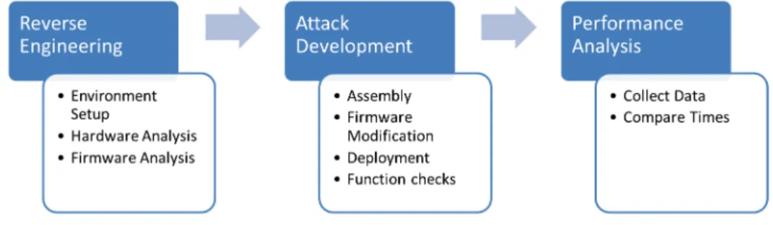
As shown in Figure 3.1, the research is conducted in three stages: reverse
engineering, attack development, and performance analysis. Reverse engineering uses hardware and firmware analysis to determine the structure of the firmware image. Attack development includes the tasks needed to modify the firmware image to execute the DoS attack. Attack development also includes functional evaluation of the attacks. In performance analysis both the unmodified and repackaged firmwares execute a process program. As both firmware images complete iterations of the process program, the time to complete the iteration is recorded. The mean program execution times from both firmware images are compared to determine if the additions to the repackaged firmware impact program execution times. Execution time comparisons are done using timing
side-channel analysis techniques developed by Dunlap [20]. Where possible, attack code makes use of primarily dormant execution paths to escape detection under normal operating conditions.
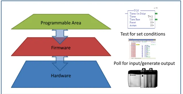
Figure 3.2: PLC Device Hierarchy.
All developed attacks execute a DoS attack against ControlLogix 1756-L61 PLC. However, the method used to trigger the DoS attack differs for each attack. Four DoS attacks are developed to replicate one of the several types of attacks proposed by Peck [40]. The first three attacks are non-persistent DoS attacks since the ControlLogix 1756-L61 PLC can be restored by either a power cycle or using the mode change key to switch modes between RUN and PROGRAM twice, clearing the fault. No permanent damage is done to the ControlLogix 1756-L61 PLC when the non-persistent attack is executed. The fourth attack is considered a persistent DoS attack because the PLC is modified in a manner that prevents recovery. The PLC requires modification using JTAG to restore it to a functional state. Note that the attacks developed in this experiment focus only on
modifying the PLC firmware, which provides the interface between the PLC hardware and programming area as shown in Figure 3.2 [8]. The repackaged firmwares execute a DoS attack under the following conditions.
1. Force the ControlLogix 1756-L61 PLC to terminate operation after a
pre-determined amount of time. This attack executes based on the value of an iterator that counts down once the ControlLogix 1756-L61 PLC begins operation. This attack is heretofore referred to as the time based non-persistent DoS attack.
2. Force the ControlLogix 1756-L61 PLC to terminate operation after a mode change command is sent. This attack executes after the ControlLogix 1756-L61 PLC mode is switched between REMOTE RUN and REMOTE PROGRAM four times. Note that the count is arbitrary and alterable. This attack is heretofore referred to as the mode change based non-persistent DoS attack.
3. Force the ControlLogix 1756-L61 PLC to terminate operation after a custom CIP command is sent. This attack executes when triggered by a customized CIP command. The CIP command uses normally unused codes to avoid interfering with legitimate commands. This attack is heretofore referred to as the CIP based non-persistent DoS attack.
4. Force the ControlLogix 1756-L61 PLC to terminate operation using a custom CIP command, and make a permanent modification to flash memory that will prevent recovery by the owner. This attack uses the same mechanism as the CIP based non-persistent DoS but adds a persistent component by writing a sentinel to flash memory that survives a power cycle. In addition to testing for the customized CIP command, this attack also tests flash memory for the sentinel value. This attack is heretofore referred to as the CIP based persistent DoS attack.
The ControlLogix 1756-L61 PLC polls each attached sensor, collects data, and then acts on that data. The firmware contains a primary loop that runs continuously, polls attached devices, and takes actions based on the inputs collected during the polling cycle. When inserting modified instructions, it is necessary to determine the location of the primary loop, or a function that executes during the loop. When inserted, the instructions can run continuous tests, divert control based on the results, and take action. To successfully carry out the four DoS attacks, it is necessary to determine the primary loop, methods used to read/write to non-volatile storage, and methods that interpret external commands.
3.2 Environment
The development environment consists of a collection of tools necessary to both analyze the existing firmware, and develop the attack. The firmware image and ControlLogix 1756-L61 PLC are also components of the development environment.
3.2.1 PLC and Firmware Specifications.
The attacks developed in this research function on the Allen-Bradley ControlLogix 1756-L61 PLC manufactured by Rockwell Automation. This PLC uses an ARM7TDMI CPU architecture [8], contains 2MB of user memory, and 478KB of I/O memory
[47]. ControlLogix 1756-L61 PLC firmware revision number 19.15.25 is the base
unmodified firmware version used in this research. All repackaged firmware revisions are alterations of this base unmodified firmware image. This baseline version is available with registration from the Allen-Bradley website [44]. Other Allen-Bradley support equipment needed by the ControlLogix 1756-L61 PLC include the 1756 PA72/C power supply, 1756-A7 chassis, and the 1756-ENBT Ethernet module for network connectivity.
3.2.2 Deployment Tools.
Existing Allen-Bradley programs are used to deploy repackaged firmware images to the PLC. The Allen-Bradley RSLinx program is required to communicate with
other Allen-Bradley devices connected to a network. Note that RSLinx only manages communication with the PLC and performs no validation of the firmware image. The Allen-Bradley ControlFLASH program is used to manage and send updated firmware images to the PLC. ControlFLASH relies on validity checks embedded in the firmware image and supporting files [8]. RSLogix 5000 from Allen Bradley is the ladder logic programming environment for the ControlLogix 1756-L61 PLC. Allen-Bradley uses ladder logic as the programming language for process control programs.
3.2.3 Firmware Analysis Tools.
The following tools are used to disassemble and trace the firmware images. IDA Pro from Hex Rays is the disassembler used to analyze the firmware. IDA Pro supports multiple ARM CPU instruction sets including ARM7TDMI which is the architecture used by the ControlLogix 1756-L61 PLC. Additional scripts built by Basnightet al. extend the functionality of IDA Pro and automate some analysis tasks [8]. The extension scripts search for known function prologues in ARM assembly to identify possible subroutines, and attempt to name functions by searching for function name strings used by a generic error handling routine in the firmware image.
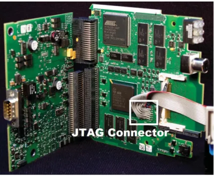
ARM Development Studio v5 and Realview ICE, both developed by ARM Holdings PLC, provide hardware debugging capability. As shown in Figure 3.3, the debugger can trace instructions, read sections of memory, capture and restore memory segments, and alter register values by connecting to the available JTAG interface on the ControlLogix 1756-L61 PLC. These functions make it possible to recover the device in case of a fault and execute specific areas of the firmware for testing.
3.2.4 Assembly Development Tools.
Assembly development is accomplished using an ARM cross compiler available in the GNUarm-linux-gnueabipackage for linux [1]. Two locally developed scripts insert the output from the cross compiler into the target malware. The first script writes
Figure 3.3: JTAG Interface.
the generated assembly instructions into the firmware beginning at the specified start address. The second script is a calculator for ARM assembly jump instructions used to modify existing jump instructions to point to desired locations.
3.2.5 Performance Analysis Tools.
Utilities developed by Dunlap provide the infrastructure for collecting and analyzing process program execution times [20]. The utilities automate the process of deploying firmware images and process programs. Additionally, the testing utilities use CIP commands to request execution time data during normal ControlLogix 1756-L61 PLC operation and record the data for later analysis. R from the R Foundation is used to test process program execution times collected from both the unmodified and repackaged firmwares for statistically significant differences.
3.3 Reverse Engineering Effort
The reverse engineering effort includes the tasks necessary to build the device attacks. Reverse engineering is divided into three tasks. The first task is the tool and firmware acquisition as previously discussed. The second task is hardware analysis which attempts to find clues about the operation of the device from the types of components used in its construction. The third task is firmware analysis where the firmware image is disassembled and analyzed.
3.3.1 Hardware Analysis.
Hardware analysis produces information necessary to identify the instruction set used in the firmware image. The first task is determining the architecture of the primary CPU through part number research or previous work [8, 48]. Other tasks include obtaining information about the attached hardware to infer interactions with the firmware image. For example, knowledge of the type of flash memory used in the device provides clues about the types of control codes referenced in the firmware image. Information about the control codes aids identification of methods that read from or write to flash memory. Knowing the ICs on the board can aid in understanding the operation of the ControlLogix 1756-L61 PLC and how the PLC interacts with the installed firmware. Information about such interactions aids attack development.
There are several tasks accomplished for hardware analysis that occur in conjunction with firmware analysis. The types of memory used in volatile and non-volatile storage are identified along with the mapping of memory layout to determine the base address of the firmware, location of the stack, and location of any critical files, vectors, or flags used by the firmware image. Knowledge of these items provide possible exploitable areas of the firmware that can be used in the repackaging attacks.
3.3.2 Firmware Analysis.
Firmware analysis is accomplished using both static and dynamic analysis. A
thorough understanding of the firmware image’s normal operations helps to craft an attack that does not interfere with the operation of the ControlLogix 1756-L61 PLC except when desired.
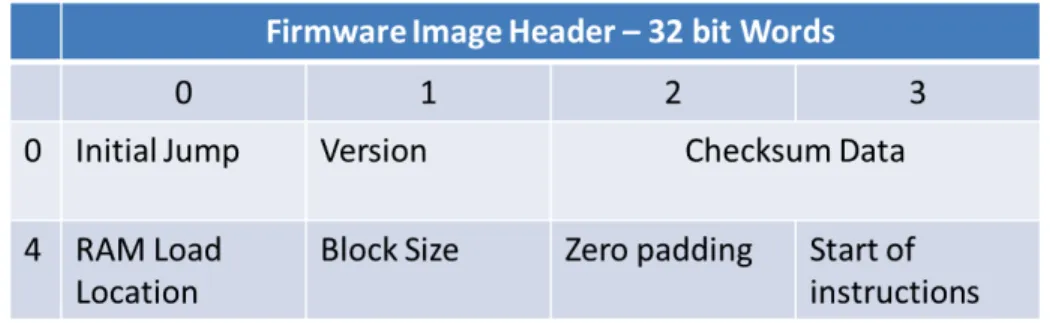
During static analysis, the firmware image is examined using IDA Pro to identify the firmware entry point, symbol tables, functions, subroutines, and fixed fields in a file header. During static analysis it is critical to identify the entry point and correct base address for the firmware image to determine the startup execution path for the PLC. This allows IDA Pro to accurately build cross-references between jump locations where relative addressing is not used. The firmware image requires additional analysis using IDA Pro extensions to identify all possible functions or subroutines by searching the firmware image for known function prologues such as stack pushes [48]. Firmware analysis also entails identifying strings in the firmware image that may indicate function names or a symbol table that can be used to associate discovered functions with an actual name.
With an understanding of the structure and flow of the firmware image, it is possible to identify areas of the firmware image that can be exploited in the attack, such as
error or fault handling routines. Since instructions are added to the firmware image, a point in the image is identified for insertion. ARM assembly makes extensive use of relative addressing for calculating program jumps and data locations. Because of the use of relative addressing, instructions cannot be inserted. The new instructions must overwrite existing instructions/data or be added to an area of the firmware image that is not addressed elsewhere.
3.4 Attack Development
During attack development, the necessary ARM instructions are developed and inserted into the firmware image in a safe location that does not overwrite existing instructions. The checksum and CRC in the repackaged firmware are updated to pass validation checks and appear as a legitimate firmware update. Once the repackaged firmware image is installed, the attack functions are checked to ensure proper operation, and ControlLogix 1756-L61 PLC stability is evaluated with each of the repackaged firmware images.
3.4.1 Assembly and Firmware Modification.
ARM instructions are assembled into a relocatable file using the ARM cross-compiler configured for the ARM7TDMI architecture. The relocatable format generated by the cross-compiler will not function on the ControlLogix 1756-L61 PLC without modification. The header information and symbol table are removed leaving only the opcodes and data. The extracted opcodes are written to the firmware image. Next, all jump instructions requiring modification are adjusted to correctly redirect execution. The offsets to the correct instruction are recomputed and the opcode altered using a hex editor. The structure of ARM opcodes is required for correct modification, which are readily available from the ARM Information Center [6].
The four DoS attacks are each structured differently. The time based non-persistent DoS attack uses a hook that replaces a function call used continuously in the firmware image. Each call to the hooking function decrements an iterator. When the iterator reaches zero, execution redirects to the failure path and the ControlLogix 1756-L61 PLC faults. There is some variability in the amount of time needed to decrement the iterator to zero since external factors not evaluated during this research may affect the execution rate of the hooked function. This time based non-persistent DoS attack only requires a point where execution flow can be safely redirected.
![Figure 2.2: Example PLC Chassis Layout [43].](https://thumb-us.123doks.com/thumbv2/123dok_us/9021575.2800017/24.918.137.788.679.971/figure-example-plc-chassis-layout.webp)
![Figure 2.3: IC Defensive Monitor Example [2].](https://thumb-us.123doks.com/thumbv2/123dok_us/9021575.2800017/31.918.241.678.106.532/figure-ic-defensive-monitor-example.webp)
![Figure 2.4: External Verification Passive Tap [32].](https://thumb-us.123doks.com/thumbv2/123dok_us/9021575.2800017/34.918.255.667.552.837/figure-external-verification-passive-tap.webp)