F O R C E S A N D N E W T O N ’ S L A W S
O F M O T I O N
&
1
As this windsurfer is propelled through the air, his motion is determined by forces due to the wind and his weight.
The relationship between the forces acting on an object and the resulting motion is discussed in this chapter.
(Tom
King/The Image Bank/Getty Images)
C
|
H
|
A
|
P
|
T
|
E
|
R
4
THE CONCEPTS OF FORCE AND MASS
In common usage, a
force
is a push or a pull, as the examples in Figure 4.1
illus-trate. In basketball, a player launches a shot by pushing on the ball. The tow bar attached
to a speeding boat pulls a water skier. Forces such as those that launch the basketball or
pull the skier are called
contact forces,
because they arise from the physical contact
be-tween two objects. There are circumstances, however, in which two objects exert forces
on one another even though they are not touching. Such forces are referred to as
noncon-tact forces
or
action-at-a-distance forces.
One example of such a noncontact force occurs
when a diver is pulled toward the earth because of the force of gravity. The earth exerts
this force even when it is not in direct contact with the diver. In Figure 4.1, arrows are
used to represent the forces. It is appropriate to use arrows, because a force is a vector
quantity and has both a magnitude and a direction. The direction of the arrow gives the
direction of the force, and the length is proportional to its strength or magnitude.
4.
1
Cutnell
Johnson
PHY
SICS,
7e
c
oming
January
2006
45807_04_p1-48 6/17/05 3:31 PM Page 12 | C H A P T E R 4 | F O RC E S A N D N E W TO N ’S L AW S O F M OT I O N
The word
mass
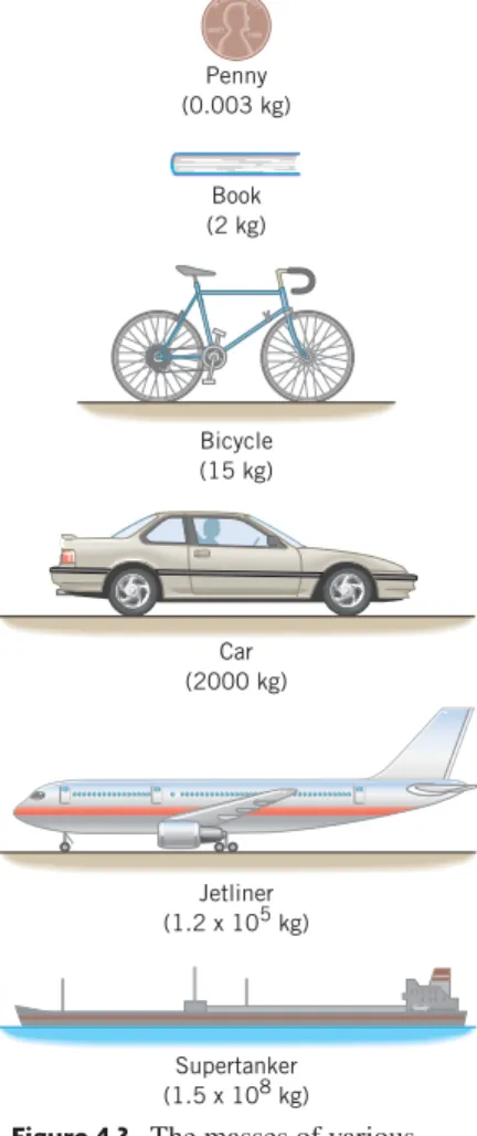
is just as familiar as the word force. A massive supertanker, for
in-stance, is one that contains an enormous amount of mass. As we will see in the next
sec-tion, it is difficult to set such a massive object into motion and difficult to bring it to a
halt once it is moving. In comparison, a penny does not contain much mass. The
empha-sis here is on the amount of mass, and the idea of direction is of no concern. Therefore,
mass is a scalar quantity.
During the seventeenth century, Isaac Newton, starting with the work of Galileo,
de-veloped three important laws that deal with force and mass. Collectively they are called
“Newton’s laws of motion” and provide the basis for understanding the effect that forces
have on an object. Because of the importance of these laws, a separate section will be
de-voted to each one.
NEWTON’S FIRST LAW OF MOTION
THE FIRST LAW
To gain some insight into Newton’s first law, think about the game of ice hockey
(Figure 4.2). If a player does not hit a stationary puck, it will remain at rest on the ice.
Af-ter the puck is struck, however, it coasts on its own across the ice, slowing down only
slightly because of friction. Since ice is very slippery, there is only a relatively small
amount of friction to slow down the puck. In fact, if it were possible to remove all friction
and wind resistance, and if the rink were infinitely large, the puck would coast forever in a
straight line at a constant speed. Left on its own, the puck would lose none of the velocity
imparted to it at the time it was struck. This is the essence of Newton’s first law of motion:
(c)
F
(b)
F
Figure 4.1 The arrow labeled represents the force that acts on (a) the basketball, (b) the water skier, and (c) the cliff diver. (a,© Nathaniel S. Butler/NBAE/Getty Images; b,© P. BeavisMasterfile; c,© Amy and Chuck Wiley/Wales/Index Stock)
F B
NEWTON’S FIRST LAW OF MOTION
An object continues in a state of rest or in a state of motion at a constant speed along a
straight line, unless compelled to change that state by a net force.
In the first law the phrase “net force” is crucial. Often, several forces act
simultane-ously on a body, and
the net force is the vector sum of all of them.
Individual forces
mat-ter only to the extent that they contribute to the total. For instance, if friction and other
op-posing forces were absent, a car could travel forever at 30 m /s in a straight line, without
using any gas after it has come up to speed. In reality gas is needed, but only so that the
engine can produce the necessary force to cancel opposing forces such as friction. This
cancellation ensures that there is no net force to change the state of motion of the car.
When an object moves at a constant speed along a straight line, its velocity is
con-stant. Newton’s first law indicates that a state of rest (zero velocity) and a state of
constant velocity are completely equivalent, in the sense that neither one requires the
ap-plication of a net force to sustain it.
The purpose served when a net force acts on an
ob-ject is not to sustain the obob-ject’s velocity, but, rather, to change it.
4.2
(a)
F
Figure 4.2 The game of ice hockey can give some insight into Newton’s laws of motion. (© Royalty-Free/Corbis Images)
4 .1 | N E W TO N ’S F I R ST L AW O F M OT I O N | 3
The SI unit for mass is the kilogram (kg), whereas the units in the CGS system and
the BE system are the gram (g) and the slug (sl), respectively. Conversion factors
be-tween these units are given on the page facing the inside of the front cover. Figure 4.3
gives the masses of various objects, ranging from a penny to a supertanker. The larger the
mass, the greater is the inertia. Often the words “mass” and “weight” are used
inter-changeably, but this is incorrect. Mass and weight are different concepts, and Section 4.7
will discuss the distinction between them.
Figure 4.4 shows a useful application of inertia. Automobile seat belts unwind freely
when pulled gently, so they can be buckled. But in an accident, they hold you safely in
place. One seat-belt mechanism consists of a ratchet wheel, a locking bar, and a
pendu-lum. The belt is wound around a spool mounted on the ratchet wheel. While the car is at
rest or moving at a constant velocity, the pendulum hangs straight down, and the locking
bar rests horizontally, as the gray part of the drawing shows. Consequently, nothing
pre-vents the ratchet wheel from turning, and the seat belt can be pulled out easily. When the
car suddenly slows down in an accident, however, the relatively massive lower part of the
pendulum keeps moving forward because of its inertia. The pendulum swings on its pivot
into the position shown in color and causes the locking bar to block the rotation of the
ratchet wheel, thus preventing the seat belt from unwinding.
AN INERTIAL REFERENCE FRAME
Newton’s first law (and also the second law) can appear to be invalid to certain
observers. Suppose, for instance, that you are a passenger riding in a friend’s car. While
the car moves at a constant speed along a straight line, you do not feel the seat pushing
against your back to any unusual extent. This experience is consistent with the first law,
which indicates that in the absence of a net force you should move with a constant
veloc-ity. Suddenly the driver floors the gas pedal. Immediately you feel the seat pressing
against your back as the car accelerates. Therefore, you sense that a force is being applied
to you. The first law leads you to believe that your motion should change, and, relative to
the ground outside, your motion does change. But
relative to the car,
you can see that
your motion does
not
change, because you remain stationary with respect to the car.
Clearly, Newton’s first law does not hold for observers who use the accelerating car as a
frame of reference. As a result, such a reference frame is said to be noninertial. All
accel-erating reference frames are noninertial. In contrast, observers for whom the law of
iner-tia is valid are said to be using
inertial reference frames
for their observations, as defined
below:
DEFINITION OF AN INERTIAL REFERENCE FRAME
An inertial reference frame is one in which Newton’s law of inertia is valid.
INERTIA AND MASS
A greater net force is required to change the velocity of some objects than of
others. For instance, a net force that is just enough to cause a bicycle to pick up speed
will cause only an imperceptible change in the motion of a freight train. In comparison to
the bicycle, the train has a much greater tendency to remain at rest. Accordingly, we say
that the train has more
inertia
than the bicycle. Quantitatively, the inertia of an object is
measured by its
mass
. The following definition of inertia and mass indicates why
New-ton’s first law is sometimes called the law of inertia:
Figure 4.4 Inertia plays a central role in one seat-belt mechanism. The gray part of the drawing applies when the car is at rest or moving at a constant velocity. The colored parts show what happens when the car suddenly slows down, as in an accident.
Figure 4.3 The masses of various objects. Seat belt Motion of car Ratchet wheel Locking bar Pivots Pendulum The physics of seat belts.
DEFINITION OF INERTIA AND MASS
Inertia is the natural tendency of an object to remain at rest or in motion at a constant
speed along a straight line. The mass of an object is a quantitative measure of inertia.
SI Unit of Inertia and Mass:
kilogram (kg)
INGOD WE TRUST LIBERTY 1996 Penny (0.003 kg) Book (2 kg) Bicycle (15 kg) Car (2000 kg) Jetliner (1.2 x 10⁵ kg) Supertanker (1.5 x 10⁸ kg) 45807_04_p1-48 6/17/05 3:31 PM Page 3
4 | C H A P T E R 4 | F O RC E S A N D N E W TO N ’S L AW S O F M OT I O N
The acceleration of an inertial reference frame is zero, so it moves with a constant
veloc-ity. All of Newton’s laws of motion are valid in inertial reference frames, and when we
apply these laws, we will be assuming such a reference frame. In particular, the earth
it-self is a good approximation of an inertial reference frame.
NEWTON’S SECOND LAW OF MOTION
Newton’s first law indicates that if no net force acts on an object, then the velocity
of the object remains unchanged. The second law deals with what happens when a net
force does act. Consider a hockey puck once again. When a player strikes a stationary
puck, he causes the velocity of the puck to change. In other words, he makes the puck
ac-celerate. The cause of the acceleration is the force that the hockey stick applies. As long
as this force acts, the velocity increases, and the puck accelerates. Now, suppose another
player strikes the puck and applies twice as much force as the first player does. The
greater force produces a greater acceleration. In fact, if the friction between the puck and
the ice is negligible, and if there is no wind resistance, the acceleration of the puck is
di-rectly proportional to the force. Twice the force produces twice the acceleration.
More-over, the acceleration is a vector quantity, just as the force is, and points in the same
di-rection as the force.
Often, several forces act on an object simultaneously. Friction and wind resistance,
for instance, do have some effect on a hockey puck. In such cases, it is the net force, or
the vector sum of all the forces acting, that is important. Mathematically, the net force is
written as
, where the Greek capital letter
(sigma) denotes the vector sum. Newton’s
second law states that the acceleration is proportional to the net force acting on the object.
In Newton’s second law, the net force is only one of two factors that determine the
acceleration. The other is the inertia or mass of the object. After all, the same net force
that imparts an appreciable acceleration to a hockey puck (small mass) will impart very
little acceleration to a semitrailer truck (large mass). Newton’s second law states that for a
given net force, the magnitude of the acceleration is inversely proportional to the mass.
Twice the mass means one-half the acceleration, if the same net force acts on both
ob-jects. Thus, the second law shows how the acceleration depends on both the net force and
the mass, as given in Equation 4.1.
F
B
NEWTON’S SECOND LAW OF MOTION
When a net external force
acts on an object of mass
m
, the acceleration that
re-sults is directly proportional to the net force and has a magnitude that is inversely
pro-portional to the mass. The direction of the acceleration is the same as the direction of
the net force.
(4.1)
SI Unit of Force:
kg
m /s
2newton
(N)
a
BF
Bm
or
F
Bma
Ba
BF
BNote that the net force in Equation 4.1 includes only the forces that the environment
exerts on the object of interest. Such forces are called
external forces.
In contrast,
inter-nal forces
are forces that one part of an object exerts on another part of the object and are
not included in Equation 4.1.
According to Equation 4.1, the SI unit for force is the unit for mass (kg) times the
unit for acceleration (m /s
2), or
The combination of kg
m /s
2is called a
newton
(N) and is a derived SI unit, not a base
unit; 1 newton
1 N
1 kg
m /s
2.
SI unit for force
(kg)
m
s
2kg
m
s
24.3
4 . 3 | N E W TO N ’S S E CO N D L AW O F M OT I O N | 5
In the CGS system, the procedure for establishing the unit of force is the same as
with SI units, except that mass is expressed in grams (g) and acceleration in cm /s
2. The
resulting unit for force is the
dyne
; 1 dyne
1 g
cm /s
2.
In the BE system, the unit for force is defined to be the pound (lb),* and the unit for
acceleration is ft /s
2. With this procedure, Newton’s second law can then be used to obtain
the unit for mass:
The combination of lb
s
2/ft is the unit for mass in the BE system and is called the
slug
(sl); 1 slug
1 sl
1 lb
s
2/ft.
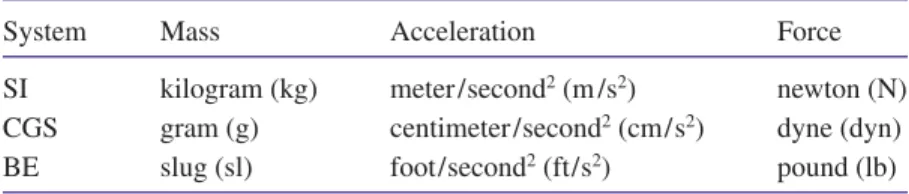
Table 4.1 summarizes the various units for mass, acceleration, and force. Conversion
factors between force units from different systems are provided on the page facing the
in-side of the front cover.
When using the second law to calculate the acceleration, it is necessary to determine the
net force that acts on the object. In this determination a
free-body diagram
helps enormously.
A free-body diagram is a diagram that represents the object and the forces that act on it. Only
the forces that
act on the object
appear in a free-body diagram. Forces that the object exerts
on its environment are not included. Example 1 illustrates the use of a free-body diagram.
▼
Example 1
|
Pushing a Stalled Car
Two people are pushing a stalled car, as Figure 4.5aindicates. The mass of the car is 1850 kg. One person applies a force of 275 N to the car, while the other applies a force of 395 N. Both forces act in the same direction. A third force of 560 N also acts on the car, but in a direction opposite to that in which the people are pushing. This force arises because of friction and the extent to which the pavement opposes the motion of the tires. Find the acceleration of the car.
Reasoning
According to Newton’s second law, the acceleration is the net force divided by the mass of the car. To determine the net force, we use the free-body diagram in Figure 4.5b. In this diagram, the car is represented as a dot, and its motion is along the xaxis. The diagram makes it clear that the forces all act along one direction. Therefore, they can be added as colin-ear vectors to obtain the net force.Solution
From Equation 4.1, the acceleration isa
(F
)/m
. The net force isF 275 N395 N560 N 110 N
Unit for mass
lb
s
2
ft
BE unit for force
lb
(unit for mass)
ft
s
2 Table 4.1 Units for Mass, Acceleration, and ForceSystem Mass Acceleration Force
SI kilogram (kg) meter /second2(m /s2) newton (N)
CGS gram (g) centimeter /second2(cm/s2) dyne (dyn)
BE slug (sl) foot/second2(ft/s2) pound (lb)
* We refer here to the gravitational version of the BE system, in which a force of one pound is defined to be the pull of the earth on a certain standard body at a location where the acceleration due to gravity is 32.174 ft/s2.
+x +y
560 N
395 N 275 N
(b) Free-body diagram of the car (a)
Opposing force = 560 N 275 N
395 N Figure 4.5 (a) Two people push a
stalled car, in opposition to a force created by friction and the pavement. (b) A free-body diagram that shows the horizontal forces acting on the car.
Problem solving insight
A free-body diagram is very helpful when applying Newton’s second law. Always start a problem by drawing the free-body diagram.
6 | C H A P T E R 4 | F O RC E S A N D N E W TO N ’S L AW S O F M OT I O N The acceleration can now be obtained:
(4.1) The plus sign indicates that the acceleration points along the xaxis, in the same direction as the net force.
▲
THE VECTOR NATURE OF NEWTON’S
SECOND LAW OF MOTION
When a football player throws a pass, the direction of the force he applies to the
ball is important. Both the force and the resulting acceleration of the ball are vector
quan-tities, as are all forces and accelerations. The directions of these vectors can be taken into
account in two dimensions by using
x
and
y
components. The net force
in Newton’s
second law has components
F
xand
F
y, while the acceleration
has components
a
xand
a
y. Consequently, Newton’s second law, as expressed in Equation 4.1, can be written
in an equivalent form as two equations, one for the
x
components and one for the
y
com-ponents:
(4.2a)
(4.2b)
This procedure is similar to that employed in Chapter 3 for the equations of
two-dimen-sional kinematics (see Table 3.1). The components in Equations 4.2a and 4.2b are scalar
components and will be either positive or negative numbers, depending on whether they
point along the positive or negative
x
or
y
axis. The remainder of this section deals with
examples that show how these equations are used.
▼
Example 2
|
Applying Newton’s Second Law Using Components
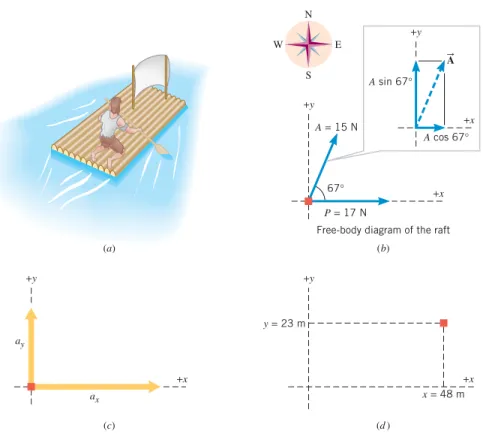
A man is stranded on a raft (mass of man and raft1300 kg), as shown in Figure 4.6a. By paddling, he causes an average force B
P
of 17 N to be applied to the raft in a direction due eastF
yma
yF
xma
xa
BF
B 0.059 m /s2 a F m 110 N 1850 kgProblem solving insight
The direction of the acceleration is always the same as the direction of the net force.
+x +y +x +y A sin 67° A = 15 N P = 17 N x = 48 m y = 23 m A cos 67° 67° A
Free-body diagram of the raft
+x ax ay N S W E +y +x +y (b) (a) (d) (c) B
Figure 4.6 (a) A man is paddling a raft, as in Examples 2 and 3. (b) The free-body diagram shows the forces and
that act on the raft. Forces acting on the raft in a direction perpendicular to the surface of the water play no role in the examples and are omitted for clarity. (c) The raft’s acceleration components axand ay. (d) In 65 s, the
components of the raft’s displacement are x48 m and y23 m. AB P B
4.
4
45807_04_p1-48 6/17/05 3:31 PM Page 64 .4 | T H E V E C TO R N AT U R E O F N E W TO N ’S S E CO N D L AW O F M OT I O N | 7 (the xdirection). The wind also exerts a force on the raft. This force has a magnitude of
15 N and points 67° north of east. Ignoring any resistance from the water, find the xand y components of the raft’s acceleration.
Reasoning
Since the mass of the man and the raft is known, Newton’s second law can be used to determine the acceleration components from the given forces. According to the form of the second law in Equations 4.2a and 4.2b, the acceleration component in a given direction is the component of the net force in that direction divided by the mass. As an aid in determin-ing the componentsF
xandF
y of the net force, we use the free-body diagram in Figure4.6
b
. In this diagram, the directions due east and due north are thex
andy
directions, re-spectively.Solution
Figure 4.6b
shows the force components:AB
The plus signs indicate that Fxpoints in the direction of the xaxis and Fypoints in the
di-rection of the yaxis. The xand ycomponents of the acceleration point in the directions of
Fx and Fy, respectively, and can now be calculated:
(4.2a)
(4.2b) These acceleration components are shown in Figure 4.6c.
▲
▼
Example 3
|
The Displacement of a Raft
At the moment the forces and begin acting on the raft in Example 2, the velocity of the raft is 0.15 m /s, in a direction due east (the xdirection). Assuming that the forces are main-tained for 65 s, find the xand ycomponents of the raft’s displacement during this time interval.
Reasoning
Once the net force acting on an object and the object’s mass have been used in Newton’s second law to determine the acceleration, it becomes possible to use the equations of kinematics to describe the resulting motion. We know from Example 2 that the accelera-tion components area
x 0.018 m/s2anda
y 0.011 m/s2, and it is given here that theinitial velocity components are
v
0x 0.15 m/s andv
0y0 m/s. Thus, Equation 3.5aand Equation 3.5b (y can be used with
t
65 s to de-termine thex
andy
components of the raft’s displacement.Solution
According to Equations 3.5a and 3.5b, thex
andy
components of the displacement areFigure 4.6dshows the final location of the raft.
▲
23 m yv0yt 1 2ayt2(0 m /s)(65 s) 1 2(0.011 m /s 2)(65 s)2 48 m xv0xt 1 2axt2(0.15 m /s)(65 s) 1 2(0.018 m /s 2)(65 s)2 0yt 1 2ayt2) (x0xt 1 2axt2)A
BP
B 0.011 m /s2 ay Fy m 14 N 1300 kg 0.018 m /s2 ax Fx m 23 N 1300 kgForce xComponent yComponent
17 N 0 N (15 N) cos 67° 6 N (15 N) sin 67° 14 N Fy 14 N Fx 17 N6 N 23 N AB P B
Need more practice?
Interactive LearningWare 4.1 A catapult on an aircraft carrier is ca-pable of accelerating a 13 300-kg plane from 0 to 56.0 m /s in a dis-tance of 80.0 m. Find the net force, assumed constant, that the jet’s engine and the catapult exert on the plane.
Related Homework:Problems 4, 6
For an interactive solution, go to www.wiley.com/college/cutnell
✔
C H E C K Y O U R U N D E R S T A N D I N G 1All of the following, except one, cause the acceleration of an object to double. Which one is it? (a) All forces acting on the object double. (b) The net force acting on the object doubles. (c) Both the net force acting on the object and the mass of the object double. (d) The mass of the object is reduced by a factor of two. (The answer is given at the end of the book.)
Background: This problem depends on the concepts of force, net force, mass, and acceleration, because Newton’s second law of motion deals with them.
For similar questions (including calculational counterparts), consult Self-Assessment Test 4.1. This test is described at the end of Section 4.5.
Problem solving insight
Applications of Newton’s second law always involve the net external force, which is the vector sum of all the external forces that act on an object. Each component of the net force leads to a corresponding component of the acceleration.
8 | C H A P T E R 4 | F O RC E S A N D N E W TO N ’S L AW S O F M OT I O N
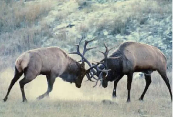
NEWTON’S THIRD LAW OF MOTION
Imagine you are in a football game. You line up facing your opponent, the ball is
snapped, and the two of you crash together. No doubt, you feel a force. But think about
your opponent. He too feels something, for while he is applying a force to you, you are
applying a force to him. In other words, there isn’t just one force on the line of
scrim-mage; there is a pair of forces. Newton was the first to realize that all forces occur in pairs
and there is no such thing as an isolated force, existing all by itself. His third law of
mo-tion deals with this fundamental characteristic of forces.
These two wapiti (elk) exert action and reaction forces on each other. (First Light/Corbis Images)
–P
+PB
B
Figure 4.7 The astronaut pushes on the spacecraft with a force . According to Newton’s third law, the spacecraft simultaneously pushes back on the astronaut with a force PB.
P B
NEWTON’S THIRD LAW OF MOTION
Whenever one body exerts a force on a second body, the second body exerts an
oppo-sitely directed force of equal magnitude on the first body.
The third law is often called the “action – reaction” law, because it is sometimes quoted as
follows: “For every action (force) there is an equal, but opposite, reaction.”
Figure 4.7 illustrates how the third law applies to an astronaut who is drifting just
outside a spacecraft and who pushes on the spacecraft with a force . According to the
third law, the spacecraft pushes back on the astronaut with a force
that is equal in
magnitude but opposite in direction. In Example 4, we examine the accelerations
pro-duced by each of these forces.
▼
Example 4
|
The Accelerations Produced by Action and Reaction Forces
Suppose that the mass of the spacecraft in Figure 4.7 is mS11 000 kg and that the mass of
the astronaut is mA92 kg. In addition, assume that the astronaut exerts a force of
36 N on the spacecraft. Find the accelerations of the spacecraft and the astronaut.
Reasoning
According to Newton’s third law, when the astronaut applies the force36 N to the spacecraft, the spacecraft applies a reaction force 36 N to the astronaut. As a result, the spacecraft and the astronaut accelerate in opposite directions. Although the ac-tion and reacac-tion forces have the same magnitude, they do not create acceleraac-tions of the same magnitude, because the spacecraft and the astronaut have different masses. According to New-ton’s second law, the astronaut, having a much smaller mass, will experience a much larger ac-celeration. In applying the second law, we note that the net force acting on the spacecraft is
, while the net force acting on the astronaut is .
Solution
Using the second law, we find that the acceleration of the spacecraft isThe acceleration of the astronaut is
▲
0.39 m /s2 a B A PB mA 92 kg36 N 0.0033 m /s2 a B S P B mS 11 000 kg36 N P B F B P B FB P B P B P B P B P B4.5
Problem solving insight
Even though the magnitudes of the action and reaction forces are always equal, these forces do not necessarily produce accelerations that have equal magnitudes, since each force acts on a different object that may have a different mass.
4 . 6 | T Y P E S O F F O RC E S : A N OV E RV I E W | 9
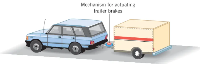
There is a clever application of Newton’s third law in some rental trailers. As Figure
4.8 illustrates, the tow bar connecting the trailer to the rear bumper of a car contains a
mechanism that can automatically actuate brakes on the trailer wheels. This mechanism
works without the need for electrical connections between the car and the trailer. When
the driver applies the car brakes, the car slows down. Because of inertia, however, the
trailer continues to roll forward and begins pushing against the bumper. In reaction,
the bumper pushes back on the tow bar. The reaction force is used by the mechanism
in the tow bar to “push the brake pedal” for the trailer.
Mechanism for actuating trailer brakes
Figure 4.8 Some rental trailers include an automatic brake-actuating
mechanism.
Newton’s Second Law ΣF = ma External Forces 1. Gravitational Force (Section 4.7) 2. Normal Force (Section 4.8) 3. Frictional Forces (Section 4.9) 4. Tension Force (Section 4.10) CONCEPTS AT A GLANCE B Figure 4.9 CONCEPTS AT A GLANCE When any of the four external forces listed here act on an object, they are included as part of the net force in any application of Newton's second law. Each of the four external forces acts on this (very) reluctant bull as the farmers join efforts to pull it aboard the boat. (Diether Endlicher/©AP/Wide World Photos)
F B
TYPES OF FORCES: AN OVERVIEW
CONCEPTS AT A GLANCE
Newton’s three laws of motion make it clear that forces
play a central role in determining the motion of an object. In the next four sections some
common forces will be discussed: the gravitational force (Section 4.7), the normal force
(Section 4.8), frictional forces (Section 4.9), and the tension force (Section 4.10). In
later chapters, we will encounter still others, such as electric and magnetic forces. It is
important to realize that Newton’s second law is always valid, regardless of which of
these forces may act on an object. One does not have a different law for every type of
common force. Thus, we need only to determine what forces are acting on an object, add
them together to form the net force, and then use Newton’s second law to determine the
object’s acceleration. The Concepts-at-a-Glance chart in Figure 4.9 illustrates this
im-portant idea.
The physics of
automatic trailer brakes.
S E L F - A S S E S S M E N T T E S T 4 . 1 www.wiley.com/college/cutnell
Test your understanding of the material in Sections 4.1–4.5:
• Newton’s First Law • Newton’s Second Law • Newton’s Third Law
4.6
10 | C H A P T E R 4 | F O RC E S A N D N E W TO N ’S L AW S O F M OT I O N
In nature there are two general types of forces, fundamental and nonfundamental.
Fundamental forces are the ones that are truly unique, in the sense that all other forces
can be explained in terms of them. Only three fundamental forces have been discovered:
1. Gravitational force
2. Strong nuclear force
3. Electroweak force
The gravitational force is discussed in the next section. The strong nuclear force plays a
primary role in the stability of the nucleus of the atom (see Section 31.2). The
elec-troweak force is a single force that manifests itself in two ways (see Section 32.6). One
manifestation is the electromagnetic force that electrically charged particles exert on one
another (see Sections 18.5, 21.2, and 21.8). The other manifestation is the so-called weak
nuclear force that plays a role in the radioactive disintegration of certain nuclei (see
Sec-tion 31.5).
Except for the gravitational force, all of the forces discussed in this chapter are
non-fundamental, because they are related to the electromagnetic force. They arise from the
interactions between the electrically charged particles that comprise atoms and molecules.
Our understanding of which forces are fundamental, however, is continually evolving. For
instance, in the 1860s and 1870s James Clerk Maxwell showed that the electric force and
the magnetic force could be explained as manifestations of a single electromagnetic force.
Then, in the 1970s, Sheldon Glashow (1932 – ), Abdus Salam (1926 – 1996), and Steven
Weinberg (1933 – ) presented the theory that explains how the electromagnetic force and
the weak nuclear force are related to the electroweak force. They received a Nobel prize
in 1979 for their achievement. Today, efforts continue that have the goal of further
reduc-ing the number of fundamental forces.
THE GRAVITATIONAL FORCE
NEWTON’S LAW OF UNIVERSAL GRAVITATION
Objects fall downward because of gravity, and Chapters 2 and 3 discuss how to
describe the effects of gravity by using a value of
g
9.80 m /s
2for the downward
accel-eration it causes. However, nothing has been said about why
g
is 9.80 m /s
2. The reason is
fascinating, as we will now see.
The acceleration due to gravity is like any other acceleration, and Newton’s second
law indicates that it must be caused by a net force. In addition to his famous three laws of
motion, Newton also provided a coherent understanding of the
gravitational force
. His
“law of universal gravitation” is stated as follows:
The constant
G
that appears in Equation 4.3 is called the
universal gravitational
constant,
because it has the same value for all pairs of particles anywhere in the universe,
no matter what their separation. The value for
G
was first measured in an experiment by
NEWTON’S LAW OF UNIVERSAL GRAVITATION
Every particle in the universe exerts an attractive force on every other particle. A
parti-cle is a piece of matter, small enough in size to be regarded as a mathematical point.
For two particles that have masses
m
1and
m
2and are separated by a distance
r
, the
force that each exerts on the other is directed along the line joining the particles (see
Figure 4.10) and has a magnitude given by
(4.3)
The symbol
G
denotes the universal gravitational constant, whose value is found
ex-perimentally to be
G
6.673
10
11N
m
2/kg
2F
G
m
1m
2r
2 r m1 m2 –F +FB BFigure 4.10 The two particles, whose masses are m1and m2, are attracted by gravitational forces FBand FB.
4.
7
4 .7 | T H E G R AV I TAT I O N A L F O RC E | 1 1
the English scientist Henry Cavendish (1731 – 1810), more than a century after Newton
proposed his law of universal gravitation.
To see the main features of Newton’s law of universal gravitation, look at the two
particles in Figure 4.10. They have masses
m
1and
m
2and are separated by a distance
r
.
In the picture, it is assumed that a force pointing to the right is positive. The gravitational
forces point along the line joining the particles and are
, the gravitational force exerted on particle 1 by particle 2
, the gravitational force exerted on particle 2 by particle 1
These two forces have equal magnitudes and opposite directions. They act on different
bodies, causing them to be mutually attracted. In fact, these forces are an action – reaction
pair, as required by Newton’s third law. Example 5 shows that the magnitude of the
gravi-tational force is extremely small for ordinary values of the masses and the distance
be-tween them.
▼
Example 5
|
Gravitational Attraction
What is the magnitude of the gravitational force that acts on each particle in Figure 4.10, as-suming m112 kg (approximately the mass of a bicycle),m225 kg, and r1.2 m?
Reasoning and Solution
The magnitude of the gravitational force can be found using Equa-tion 4.3:For comparison, you exert a force of about 1 N when pushing a doorbell, so that the gravita-tional force is exceedingly small in circumstances such as those here. This result is due to the fact that Gitself is very small. However, if one of the bodies has a large mass, like that of the earth (5.981024kg), the gravitational force can be large.
▲
As expressed by Equation 4.3, Newton’s law of gravitation applies only to particles.
However, most familiar objects are too large to be considered particles. Nevertheless, the
law of universal gravitation can be applied to such objects with the aid of calculus.
New-ton was able to prove that an object of finite size can be considered to be a particle for
purposes of using the gravitation law, provided the mass of the object is distributed with
spherical symmetry about its center. Thus, Equation 4.3 can be applied when each object
is a sphere whose mass is spread uniformly over its entire volume. Figure 4.11 shows this
kind of application, assuming that the earth and the moon are such uniform spheres of
matter. In this case,
r
is the distance
between the centers of the spheres
and not the
dis-tance between the outer surfaces. The gravitational forces that the spheres exert on each
other are the same as if the entire mass of each were concentrated at its center. Even if the
objects are not uniform spheres, Equation 4.3 can be used to a good degree of
approxima-tion if the sizes of the objects are small relative to the distance of separaapproxima-tion
r
.
WEIGHT
The weight of an object arises because of the gravitational pull of the earth.
1.4108 N FG m1m2 r2 (6.6710 11 Nm2/ kg2) (12 kg)(25 kg) (1.2 m)2F
BF
B Moon r Earth ME ME MM MM +FB –FB +FB –BFFigure 4.11 The gravitational force that each uniform sphere of matter exerts on the other is the same as if each sphere were a particle with its mass
concentrated at its center. The earth (mass ME) and the moon (mass MM) approximate such uniform spheres.
DEFINITION OF WEIGHT
The weight of an object on or above the earth is the gravitational force that the earth
exerts on the object. The weight always acts downward, toward the center of the earth.
On or above another astronomical body, the weight is the gravitational force exerted
on the object by that body.
SI Unit of Weight:
newton (N)
45807_04_p1-48 6/17/05 3:31 PM Page 1112 | C H A P T E R 4 | F O RC E S A N D N E W TO N ’S L AW S O F M OT I O N
Using
W
for the magnitude of the weight,*
m
for the mass of the object, and
M
Efor
the mass of the earth, it follows from Equation 4.3 that
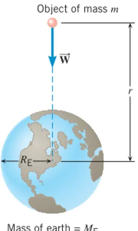
(4.4)
Equation 4.4 and Figure 4.12 both emphasize that an object has weight whether or not it
is resting on the earth’s surface, because the gravitational force is acting even when the
distance
r
is not equal to the radius
R
Eof the earth. However, the gravitational force
be-comes weaker as
r
increases, since
r
is in the denominator of Equation 4.4. Figure 4.13,
for example, shows how the weight of the Hubble Space Telescope becomes smaller as
the distance
r
from the center of the earth increases. In Example 6 the telescope’s weight
is determined when it is on earth and in orbit.
▼
Example 6
|
The Hubble Space Telescope
The mass of the Hubble Space Telescope is 11 600 kg. Determine the weight of the telescope (a) when it was resting on the earth and (b) as it is in its orbit 598 km above the earth’s surface.
Reasoning
The weight of the Hubble Space Telescope is the gravitational force exerted on it by the earth. According to Equation 4.4, the weight varies inversely as the square of the radial distancer
. Thus, we expect the telescope’s weight on the earth’s surface (rsmaller) to be greater than its weight in orbit (rlarger).Solution
(a) On the earth’s surface, the weight is given by Equation 4.4 with r6.38 106m (the earth’s radius):(b) When the telescope is 598 km above the surface, its distance from the center of the earth is
The weight now can be calculated as in part (a), except that the new value of rmust be used: . As expected, the weight is less in orbit.
▲
The space age has forced us to broaden our ideas about weight. For instance, an
as-tronaut weighs only about one-sixth as much on the moon as on the earth. To obtain his
weight on the moon from Equation 4.4, it is only necessary to replace
M
Eby
M
M(the
mass of the moon) and let
r
R
M(the radius of the moon).
RELATION BETWEEN MASS AND WEIGHT
Although massive objects weigh a lot on the earth, mass and weight are not the
same quantity. As Section 4.2 discusses, mass is a quantitative measure of inertia. As
such, mass is an intrinsic property of matter and does not change as an object is moved
from one location to another. Weight, in contrast, is the gravitational force acting on the
object and can vary, depending on how far the object is above the earth’s surface or
whether it is located near another body such as the moon.
The relation between weight
W
and mass
m
can be written in two ways:
(4.4)
(4.5)
g
W
m
m
G
M
Er
2W
W0.950105 N r6.38106 m598103 m6.98106 m W1.14105 N WG MEm r2 (6.671011 Nm2/ kg2)(5.981024 kg)(11 600 kg) (6.38106 m)2W
G
M
Em
r
2 r W Object of mass m RE Mass of earth = ME 5 0.2 0 0.4 0.6 0.8 1.0 10 15 20 r (× 106 m) RE = 6.38 x 10⁶ m W ( × 10 5 N)Figure 4.12 On or above the earth, the weight of an object is the
gravitational force exerted on the object by the earth.
W oB
Figure 4.13 The weight of the Hubble Space Telescope decreases as the telescope gets farther from the earth. The distance from the center of the earth to the telescope is r.
* Often, the word “weight” and the phrase “magnitude of the weight” are used interchangeably, even though weight is a vector. Generally, the context makes it clear when the direction of the weight vector must be taken into account.
p
Problem solving insight
When applying Newton’s gravitation law to uniform spheres of matter, remember that the distance ris between the centers of the spheres, not between the surfaces. 45807_04_p1-48 6/20/05 7:39 AM Page 12
4 .7 | T H E G R AV I TAT I O N A L F O RC E | 1 3
Equation 4.4 is Newton’s law of universal gravitation, and Equation 4.5 is Newton’s
sec-ond law (net force equals mass times acceleration) incorporating the acceleration
g
due to
gravity. These expressions make the distinction between mass and weight stand out. The
weight of an object whose mass is
m
depends on the values for the universal gravitational
constant
G
, the mass
M
Eof the earth, and the distance
r
. These three parameters together
determine the acceleration
g
due to gravity. The specific value of
g
9.80 m /s
2applies
only when
r
equals the radius
R
Eof the earth. For larger values of
r
, as would be the case
on top of a mountain, the effective value of
g
is less than 9.80 m /s
2. The fact that
g
de-creases as the distance
r
increases means that the weight likewise decreases. The mass of
the object, however, does not depend on these effects and does not change. Conceptual
Example 7 further explores the difference between mass and weight.
▼
Conceptual Example 7
|
Mass Versus Weight
A vehicle is being designed for use in exploring the moon’s surface and is being tested on earth, where it weighs roughly six times more than it will on the moon. In one test, the accel-eration of the vehicle along the ground is measured. To achieve the same accelaccel-eration on the moon, will the net force acting on the vehicle be greater than, less than, or the same as that re-quired on earth?
Reasoning and Solution
The net force required to accelerate the vehicle is specified by Newton’s second law as m , where mis the vehicle’s mass and is the acceleration along the ground. For a given acceleration, the net force depends only on the mass. But the mass is an intrinsic property of the vehicle and is the same on the moon as it is on the earth. Therefore, the same net force would be required for a given acceleration on the moon as on the earth. Do not be misled by the fact that the vehicle weighs more on earth. The greater weight occurs only because the earth’s mass and radius are different than the moon’s. In any event,in Newton’s second law, the net force is proportional to the vehicle’s mass, not its weight.Related Homework:
Problems 22, 87▲
a B a B F B F BThe Lunar Roving Vehicle that astronaut Eugene Cernan is driving on the moon and the Lunar Excursion Module (behind the Roving Vehicle) have the same mass that they have on the earth. However, their weight is different on the moon than on the earth, as Conceptual Example 7 discusses. (NASA/Johnson Space Center)
✔
C H E C K Y O U R U N D E R S T A N D I N G 2One object has a mass m1, and a second object has a mass m2, which is greater than m1.
The two are separated by a distance 2d. A third object has a mass m3. All three objects are
located on the same straight line. The net gravitational force acting on the third object is zero. Which of the drawings correctly represents the locations of the objects? The answer is given at the end of the book.)
m2 m1 m 3 d d m2 m1 m 3 d d m2 m1 m 3 d d (a) (b) m2 m1 m 3 d d (d) (c)
Background: The gravitational force and Newton’s law of universal gravitation are the focus
of this problem.
For similar questions (including calculational counterparts), consult Self-Assessment Test 4.2. This test is described at the end of Section 4.10.
Problem solving insight
Mass and weight are different quantities. They cannot be interchanged when solving problems.
14 | C H A P T E R 4 | F O RC E S A N D N E W TO N ’S L AW S O F M OT I O N
THE NORMAL FORCE
THE DEFINITION AND INTERPRETATION
OF THE NORMAL FORCE
In many situations, an object is in contact with a surface, such as a tabletop.
Be-cause of the contact, there is a force acting on the object. The present section discusses
only one component of this force, the component that acts perpendicular to the surface.
The next section discusses the component that acts parallel to the surface. The
perpendic-ular component is called the
normal force.
Figure 4.14 shows a block resting on a horizontal table and identifies the two forces
that act on the block, the weight
and the normal force
N. To understand how an
inani-mate object, such as a tabletop, can exert a normal force, think about what happens when
you sit on a mattress. Your weight causes the springs in the mattress to compress. As a
re-sult, the compressed springs exert an upward force (the normal force) on you. In a similar
manner, the weight of the block causes invisible “atomic springs” in the surface of the
table to compress, thus producing a normal force on the block.
Newton’s third law plays an important role in connection with the normal force. In
Figure 4.14, for instance, the block exerts a force on the table by pressing down on it.
Consistent with the third law, the table exerts an oppositely directed force of equal
magni-tude on the block. This reaction force is the normal force. The magnimagni-tude of the normal
force indicates how hard the two objects press against each other.
If an object is resting on a horizontal surface and there are no vertically acting forces
except the object’s weight and the normal force, the magnitudes of these two forces are
equal; that is,
F
NW
. This is the situation in Figure 4.14. The weight must be balanced
by the normal force for the object to remain at rest on the table. If the magnitudes of these
forces were not equal, there would be a net force acting on the block, and the block would
accelerate either upward or downward, in accord with Newton’s second law.
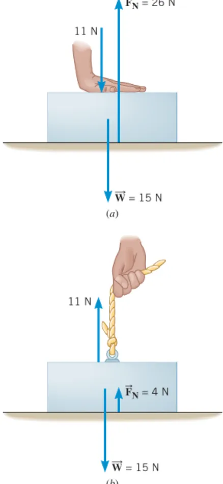
If other forces in addition to
and
Nact in the vertical direction, the
magnitudes of the normal force and the weight are no longer equal. In Figure 4.15
a
, for
instance, a box whose weight is 15 N is being pushed downward against a table. The
pushing force has a magnitude of 11 N. Thus, the total downward force exerted on the
box is 26 N, and this must be balanced by the upward-acting normal force if the box is to
remain at rest. In this situation, then, the normal force is 26 N, which is considerably
larger than the weight of the box.
Figure 4.15
b
illustrates a different situation. Here, the box is being pulled upward by
a rope that applies a force of 11 N. The net force acting on the box due to its weight and
the rope is only 4 N, downward. To balance this force, the normal force needs to be only
4 N. It is not hard to imagine what would happen if the force applied by the rope were
in-creased to 15 N — exactly equal to the weight of the box. In this situation, the normal
force would become zero. In fact, the table could be removed, since the block would be
supported entirely by the rope. The situations in Figure 4.15 are consistent with the idea
that the magnitude of the normal force indicates how hard two objects press against each
other. Clearly, the box and the table press against each other harder in part
a
of the picture
than in part
b
.
Like the box and the table in Figure 4.15, various parts of the human body press
against one another and exert normal forces. Example 8 illustrates the remarkable ability
of the human skeleton to withstand a wide range of normal forces.
FB
W
oB F BW
oBDEFINITION OF THE NORMAL FORCE
The normal force
Nis one component of the force that a surface exerts on an object
with which it is in contact — namely, the component that is perpendicular to the
surface.
FB FN W B 11 N FN = 26 N W = 15 N (a) 11 N W = 15 N (b) FN = 4 N B BFigure 4.14 Two forces act on the block, its weight and the normal force Nexerted by the surface of the
table. FB
W oB
Figure 4.15 (a) The normal force Nis
greater than the weight of the box, because the box is being pressed downward with an 11-N force. (b) The normal force is smaller than the weight, because the rope supplies an upward force of 11 N that partially supports the box.
F B
4.8
4 . 8 | T H E N O R M A L F O RC E | 1 5
▼
Example 8
|
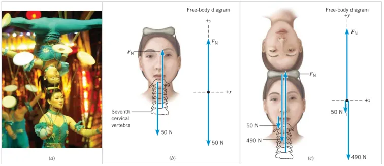
A Balancing Act
In a circus balancing act, a woman performs a headstand on top of a standing performer’s head, as Figure 4.16aillustrates. The woman weighs 490 N, and the standing performer’s head and neck weigh 50 N. It is primarily the seventh cervical vertebra in the spine that supports all the weight above the shoulders. What is the normal force that this vertebra exerts on the neck and head of the standing performer (a) before the act and (b) during the act?
Reasoning
To begin, we draw a free-body diagram for the neck and head of the standing per-former. Before the act, there are only two forces, the weight of the standing performer’s head and neck, and the normal force. During the act, an additional force is present due to the woman’s weight. In both cases, the upward and downward forces must balance for the head and neck to remain at rest. This condition of balance will lead us to values for the normal force.Solution
(a) Figure 4.16bshows the free-body diagram for the standing performer’s head and neck before the act. The only forces acting are the normal force Nand the 50-N weight. These two forces must balance for the standing performer’s head and neck to remain at rest. Therefore, the seventh cervical vertebra exerts a normal force of .(b) Figure 4.16c shows the free-body diagram that applies during the act. Now, the total downward force exerted on the standing performer’s head and neck is 50 N490 N540 N, which must be balanced by the upward normal force, so that .
▲
In summary, the normal force does not necessarily have the same magnitude as the
weight of the object. The value of the normal force depends on what other forces are
present. It also depends on whether the objects in contact are accelerating. In one
situa-tion that involves accelerating objects, the magnitude of the normal force can be regarded
as a kind of “apparent weight,” as we will now see.
APPARENT WEIGHT
Usually, the weight of an object can be determined with the aid of a scale.
How-ever, even though a scale is working properly, there are situations in which it does not
give the correct weight. In such situations, the reading on the scale gives only the
“appar-ent” weight, rather than the gravitational force or “true” weight. The apparent weight is
the force that the object exerts on the scale with which it is in contact.
FN540 N FN50 N FB +x +y +x +y FN FN FN FN 50 N 50 N 50 N 490 N 490 N 50 N (b) (a) (c) Seventh cervical vertebra
Free-body diagram Free-body diagram
Figure 4.16 (a) A young woman keeps her balance during a performance by China’s Sincuan Acrobatic group. A free-body diagram is shown (above the shoulders) for the standing performer (b) before the act and (c) during the act. For convenience, the scales used for the vectors in parts band care different. (© SUPRI/Reuters/Landov LLC)
The physics of
the human skeleton.
16 | C H A P T E R 4 | F O RC E S A N D N E W TO N ’S L AW S O F M OT I O N
To see the discrepancies that can arise between true weight and apparent weight,
con-sider the scale in the elevator in Figure 4.17. The reasons for the discrepancies will be
ex-plained shortly. A person whose true weight is 700 N steps on the scale. If the elevator is
at rest or moving with a constant velocity (either upward or downward), the scale
regis-ters the true weight, as Figure 4.17
a
illustrates.
If the elevator is accelerating, the apparent weight and the true weight are not equal.
When the elevator accelerates upward, the apparent weight is greater than the true weight,
as Figure 4.17
b
shows. Conversely, if the elevator accelerates downward, as in part
c
, the
apparent weight is less than the true weight. In fact, if the elevator falls freely, so its
ac-celeration is equal to the acac-celeration due to gravity, the apparent weight becomes zero,
as part
d
indicates. In a situation such as this, where the apparent weight is zero, the
per-son is said to be “weightless.” The apparent weight, then, does not equal the true weight if
the scale and the person on it are accelerating.
The discrepancies between true weight and apparent weight can be understood with
the aid of Newton’s second law. Figure 4.18 shows a free-body diagram of the person in
the elevator. The two forces that act on him are the true weight
m
and the normal
force
Nexerted by the platform of the scale. Applying Newton’s second law in the
verti-cal direction gives
where
a
is the acceleration of the elevator and person. In this result, the symbol
g
stands
for the magnitude of the acceleration due to gravity and can never be a negative quantity.
However, the acceleration
a
may be either positive or negative, depending on whether the
elevator is accelerating upward (
) or downward (
). Solving for the normal force
F
Nshows that
(4.6)
In Equation 4.6,
F
Nis the magnitude of the normal force exerted on the person by the
scale. But in accord with Newton’s third law,
F
Nis also the magnitude of the downward
force that the person exerts on the scale — namely, the apparent weight.
Equation 4.6 contains all the features shown in Figure 4.17. If the elevator is not
ac-celerating,
a
0 m /s
2, and the apparent weight equals the true weight. If the elevator
ac-celerates upward,
a
is positive, and the equation shows that the apparent weight is greater
than the true weight. If the elevator accelerates downward,
a
is negative, and the apparent
weight is less than the true weight. If the elevator falls freely,
a
g
, and the apparent
weight is zero. The apparent weight is zero because when both the person and the scale
fall freely, they cannot push against one another. In this text, when the weight is given, it
is assumed to be the true weight, unless stated otherwise.
True 123 weight Apparent 123 weight
F
Nmg
ma
F
yF
Nmg
ma
F
Bg
BW
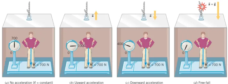
oB(a) No acceleration (v = constant) (b) Upward acceleration (c) Downward acceleration (d) Free-fall 0 700 W = 700 N 0 W = 700 N 0 400 W = 700 N 0 W = 700 N a a a = g 1000
Figure 4.17 (a) When the elevator is not accelerating, the scale registers the true weight (W700 N) of the person. (b) When the elevator accelerates upward, the apparent weight (1000 N) exceeds the true weight. (c) When the elevator accelerates downward, the apparent weight (400 N) is less than the true weight. (d) The apparent weight is zero if the elevator falls freely — that is, if it falls with the acceleration due to gravity. +x W = mg FN +y B
Figure 4.18 A free-body diagram showing the forces acting on the person riding in the elevator of Figure 4.17. is the true weight, and Nis the normal
force exerted on the person by the platform of the scale.
F
B W
oB 45807_04_p1-48 6/17/05 3:31 PM Page 16
4 .9 | STAT I C A N D K I N E T I C F R I C T I O N A L F O RC E S | 1 7
STATIC AND KINETIC FRICTIONAL FORCES
When an object is in contact with a surface, there is a force acting on the object.
The previous section discusses the component of this force that is perpendicular to the
surface, which is called the normal force. When the object moves or attempts to move
along the surface, there is also a component of the force that is parallel to the surface.
This parallel force component is called the
frictional force,
or simply
friction.
In many situations considerable engineering effort is expended trying to reduce
fric-tion. For example, oil is used to reduce the friction that causes wear and tear in the
pis-tons and cylinder walls of an automobile engine. Sometimes, however, friction is
ab-solutely necessary. Without friction, car tires could not provide the traction needed to
move the car. In fact, the raised tread on a tire is designed to maintain friction. On a wet
road, the spaces in the tread pattern (see Figure 4.19) provide channels for the water to
collect and be diverted away. Thus, these channels largely prevent the water from coming
between the tire surface and the road surface, where it would reduce friction and allow
the tire to skid.
Surfaces that appear to be highly polished can actually look quite rough when
exam-ined under a microscope. Such an examination reveals that two surfaces in contact touch
only at relatively few spots, as Figure 4.20 illustrates. The microscopic area of contact for
these spots is substantially less than the apparent macroscopic area of contact between the
surfaces — perhaps thousands of times less. At these contact points the molecules of the
different bodies are close enough together to exert strong attractive intermolecular forces
on one another, leading to what are known as “cold welds.” Frictional forces are
associ-ated with these welded spots, but the exact details of how frictional forces arise are not
well understood. However, some empirical relations have been developed that make it
possible to account for the effects of friction.
Figure 4.21 helps to explain the main features of the type of friction known as
static
friction.
The block in this drawing is initially at rest on a table, and as long as there is no
attempt to move the block, there is no static frictional force. Then, a horizontal force
is
applied to the block by means of a rope. If
is small, as in part
a
, experience tells us that
the block still does not move. Why? It does not move because the static frictional force
sexactly cancels the effect of the applied force. The direction of
sis opposite to that of ,
and the magnitude of
sequals the magnitude of the applied force,
f
sF
. Increasing the
applied force in Figure 4.21 by a small amount still does not cause the block to move.
There is no movement because the static frictional force also increases by an amount that
cancels out the increase in the applied force (see part
b
of the drawing). If the applied
f
BF
Bf
Bf
BF
BF
B Microscopic contact pointsFigure 4.19 This photo, shot from underneath a transparent surface, shows a tire rolling under wet conditions. The channels in the tire collect and divert water away from the regions where the tire contacts the surface, thus providing better traction. (Courtesy Goodyear Tire & Rubber Co.)
Figure 4.20 Even when two highly polished surfaces are in contact, they touch only at relatively few points.
F
No movement (a)
No movement (b)
When movement just begins (c) F fsMAX F fs fs B B B
Figure 4.21 Applying a small force to the block, as in parts aand b, produces no movement, because the static frictional force sexactly balances
the applied force. (c) The block just begins to move when the applied force is slightly greater than the maximum static frictional force fsMAX.
B f B F B