ECCCII-Based Current-Mode Universal Filter
with Orthogonal Control of
o
and Q
Montree KUMNGERN
1, Fabian KHATEB
2,3, Pattarapong PHASUKKIT
1,
Supan TUNGJITKUSOLMUN
1, Somyot JUNNAPIYA
11 Faculty of Engineering, King Mongkut’s Institute of Technology Ladkrabang, Bangkok 1520 Thailand 2 Dept. of Microelectronics, Brno University of Technology, Technická 10, Brno, Czech Republic
3 Czech Technical University in Prague, Faculty of Biomedical Engineering, Nám. Sítná 3105, Kladno, Czech Republic
[email protected], [email protected], [email protected], [email protected], [email protected]
Abstract. This paper presents a new current-mode cur-rent-controlled four-input five-output universal filter em-ploying one current-controlled current conveyor (CCCII), one electronically tunable CCCII and two grounded ca-pacitors. The proposed configuration provides lowpass, bandpass, highpass, bandstop and allpass current re-sponses that taken from the high-output impedance termi-nals, which enable easy cascadability of the current-mode operation. The filter also offers both orthogonal and elec-tronic controls of the natural frequency and the quality factor through adjusting the bias current of the CCCIIs. For realizing all the filter responses, the proposed filter does not require passive component-matching condition and both active and passive sensitivities are low. In addi-tion, a new current-mode current-controlled single-input five-output universal filter can be achieved by using an additional multiple-output minus-type CCCII. The proposed filter is simulated using PSPICE simulations to confirm the theoretical analysis.
Keywords
Universal filter, current-mode circuit, electronically tunable current conveyor, analog filter.
1.
Introduction
In the present, current-mode signal processing circuits based on second generation current-conveyors (CCIIs) have received considerable attention owing to the fact that their bandwidth, linearity and dynamic range performances are better than op-amp-based voltage-mode signal proc-essing circuits [1], [2]. Especially, current-mode circuit provides simple summation/subtraction signals of currents in node, which results to simple circuitry. Many current-mode universal filters using current conveyors as active elements have been proposed [3]-[43]. A number of CCII-based current-mode universal filters have been presented [3]-[9]. In [3]-[6] single-input multiple-output (SIMO) current-mode universal filters using CCIIs have been re-ported. Generally, SIMO filter can simultaneously realize
three basic filter functions, i.e. lowpass (LP), bandpass (BP) and highpass (HP). However, for the realizations of allpass (AP) and bandstop (BS) functions, some of SIMO filters require passive or signal-matching condition. For more convenience and versatility, the multiple-input multi-ple-output (MIMO) universal filters could be used. The employment of the MIMO configuration may lead to a reduction of number of active elements for circuit realiza-tion. This type of filter, in comparison with the SIMO fil-ter, provides a variety of circuit characteristic with differ-ent input and output currdiffer-ents, and usually does not require any parameter matching conditions. Moreover, to realize all the standard biquadratic filter functions, the configura-tion with multiple inputs seems to be more suitable than the single input configuration [11]. In [7]-[9] CCIIs-based MIMO current-mode universal filter have been presented. Most of the MIMO universal filters based on CCIIs suffer from lack of electronic tuning. By using the second-gen-eration current-controlled current conveyor (CCCII) intro-duced by Fabre et al. [10], current conveyor applications can be extended to the domain of electronically tunable functions. Many current-mode CCCII-based universal filters have been proposed in the technical literatures [11]-[42]. In [11]-[16] multiple-input universal filters were proposed while single-input universal filters were proposed in [17]-[41]. However, some of these filters do not benefit from orthogonal control of the natural frequency o and the
quality factor Q.
In this paper, we propose a new electronically tunable current-mode four-input five-output universal filter using one CCCII, one electronically tunable CCCII and two grounded capacitors [42], which is advantageous in view of integrated circuit implementation. The proposed circuits can simultaneously realize LP, BP, HP, BS and AP current responses at a high impedance output terminal permitting easy cascadability of the current-mode operation. The cir-cuit parameters o and Q can be tuned separately and
elec-tronically by adjusting the bias current of CCCII. More-over, high Q-value filters can be obtained. For the realiza-tion of all the filter responses no component-matching conditions are required. Both active and passive sensitivi-ties are low. In addition, a new current-mode single-input
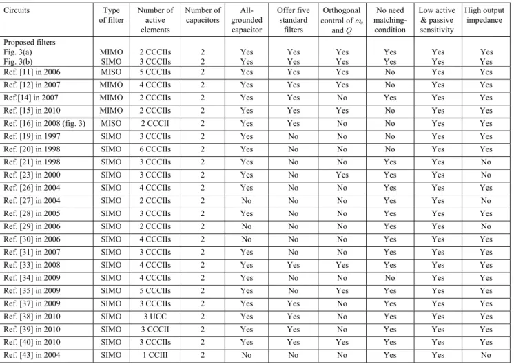
five-output universal filter can be also achieved by adding a multiple-output minus-type CCCII into the proposed filter. This new circuit has low-input and high-output im-pedance levels. The comparison between the proposed circuits and some previously CCCII-based filters is sum-marized in Tab. 1.
2.
Proposed Circuit
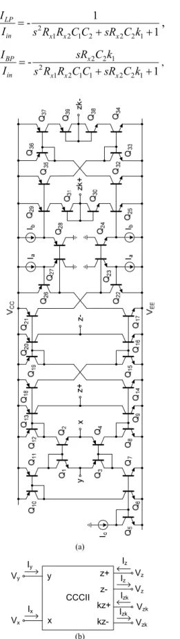
The well-known schematic for CCCII, implemented with bipolar technology is shown in Fig. 1 [10]. According to Fig. 1, the CCCII has a unity voltage gain between ter-minal y and x and a unity current gain between terter-minal x and z. The terminals y and z possess high impedance level and the x terminal has the Rx, which can be given by
2 T x o V R I (1)
The Rx is an inner resistance of a translinear mixed loop
(Q1 to Q4) with grounded resistor equivalent controlled by
bias current Io, where VT is the thermal voltage ( 25 mV).
The translinear current conveyor with controlled current
gain can be obtained by modifying the original circuit of the CCCII in Fig. 1 and adding additional current mirror with adjustable gain as shown in Fig. 2 [44] to obtain the required current gain at z terminal. Also, the multiple-out-put translinear current conveyor can be obtained by adding additional current mirrors and cross-coupled current mir-rors to obtain the required plus and minus type outputs, respectively [45].
Fig. 1. Schematic implementation for CCCII.
Circuits Type of filter Number of active elements Number of capacitors All-grounded capacitor Offer five standard filters Orthogonal control of o and Q No need matching-condition Low active & passive sensitivity High output impedance Proposed filters Fig. 3(a) Fig. 3(b) MIMO SIMO 2 CCCIIs 3 CCCIIs 2 2 Yes Yes Yes Yes Yes Yes Yes Yes Yes Yes Yes Yes Ref. [11] in 2006 MISO 5 CCCIIs 2 Yes Yes Yes No Yes Yes Ref. [12] in 2007 MIMO 4 CCCIIs 2 Yes Yes Yes No Yes Yes Ref.[14] in 2007 MIMO 2 CCCIIs 2 Yes Yes No Yes Yes Yes Ref. [15] in 2010 MIMO 2 CCCIIs 2 Yes Yes Yes No Yes Yes Ref. [16] in 2008 (fig. 3) MISO 2 CCCII 2 Yes Yes No No Yes Yes
Ref. [19] in 1997 SIMO 3 CCCIIs 2 Yes No No No Yes Yes
Ref. [20] in 1998 SIMO 6 CCCIIs 2 Yes No No No Yes Yes
Ref. [21] in 1998 SIMO 3 CCCIIs 2 Yes No No Yes Yes No Ref. [23] in 2000 SIMO 3 CCCIIs 2 Yes No Yes Yes Yes No Ref. [26] in 2004 SIMO 4 CCCIIs 2 Yes No No Yes Yes Yes
Ref. [27] in 2004 SIMO 2 CCCIIs 2 No No No Yes Yes No
Ref. [28] in 2005 SIMO 3 CCCIIs 2 Yes No No Yes Yes Yes
Ref. [29] in 2006 SIMO 2 CCCIIs 2 No No No Yes Yes No
Ref. [30] in 2006 SIMO 4 CCCIIs 2 No No No Yes Yes Yes Ref. [31] in 2007 SIMO 3 CCCIIs 2 Yes No No Yes Yes Yes Ref. [33] in 2008 SIMO 4 CCCIIs 2 Yes Yes Yes Yes Yes Yes
Ref. [34] in 2009 SIMO 4 CCCIIs 2 Yes No No No Yes Yes
Ref. [35] in 2009 SIMO 5 CCCIIs 2 Yes No Yes Yes Yes Yes Ref. [37] in 2009 SIMO 3 CCCIIs 2 Yes Yes No Yes Yes Yes
Ref. [38] in 2010 SIMO 3 UCC 2 Yes Yes No Yes Yes Yes
Ref. [39] in 2010 SIMO 3 CCCII 2 Yes Yes No Yes Yes Yes Ref. [40] in 2010 SIMO 3 CCCIIs 2 Yes Yes Yes Yes Yes Yes
Ref. [43] in 2004 SIMO 1 CCIII 2 No No No Yes Yes No
Note: MISO is multiple-input and single-output.
(a)
(b)
Fig. 2. Current mirrors with adjustable current gain: (a) positive-type, (b) negative-type.
Fig. 3(a) and (b) shows respectively the schematic and the symbol of the electronically tunable CCCII [42]. It has a unity voltage gain between terminals y and x and tunable k current gain between terminals x and z. The latter property makes it different from the current conveyor and hence the name electronically tunable CCCII (ECCCII). A few electronically tunable current conveyors were al-ready described in the literature [46]-[48]. However, these devices are not suitable for electronic-control of o and
high Q-value biquadratic filter. The schematic of ECCCII in Fig. 3 is characterized by the relationship:
0 0 0 1 0 0 1 0 0 0 y y x x x z z zk I V V R I I V I k (2)
The current gain k of the ECCCII can be expressed as [42] a b I k I (3)
It is evident that the signal is amplified by the factor k and this factor can be varied linearly and controlled by adjusting the Ia/Ib.
Fig. 4 shows the block diagram of the proposed universal filter. It comprises of two integrators and one amplifier. Based on Fig. 4 the proposed current-mode universal filter is shown in Fig. 5. From Fig. 5(a), CCCII1
and C1 operate as the first integrator (1/s1) and current
amplifier (k) while CCCII2 and C2 operate as the second
integrator (1/s2). The filter in Fig. 5(a) is consisted of one
CCCII, one ECCCII and two grounded capacitors and hence the name ECCCII-based universal filter. The use of grounded capacitor makes the proposed filter ideal for integration point of view [49], [50]. Using (2) and nodal
analysis, the transfer functions of the proposed biquadratic filter in Fig. 5(a) can be expressed as
2 1 2 1 2 2 2 1 1 -1 LP in x x x I I s R R C C sR C k
,
(4) 2 2 1 2 1 2 1 1 2 2 1 -1 x BP in x x x sR C k I I s R R C C sR C k , (5) (a) Vx Vy Iz Ix Iy CCCII x y z+ kz-Vz Izk Vz Vzk kz+ Izk Vzk z-Iz (b)Fig. 3. ECCCII; (a) bipolar implementation; (b) circuit symbol.
Fig. 4. Block diagram of proposed universal filter. 2 1 2 1 2 2 1 2 1 2 2 2 1 1 x x HP in x x x s R R C C I I s R R C C sR C k
,
(6) 2 1 2 1 2 2 1 2 1 2 2 2 1 1 1 BS x x in x x x I s R R C C I s R R C C sR C k ,
(7) 2 1 2 1 2 2 2 1 2 1 2 1 2 2 2 1 - 1 1 x x x AP in x x x s R R C C sR C k I I s R R C C sR C k .
(8)Therefore, five filter functions can be achieved. It should be mentioned that there is no component-matching condition for realizing all the standard type biquadratic filtering functions. The natural frequency o and the
quality factor Q are given by
1 2 1 2 1 o x x R R C C
,
(9) 1 1 1 2 2 1 x x R C Q k R C (10) (a) (b)with 1 1 1 a b I k I (11)
where Ia1 and Ib1 are the bias currents of CCCII1. If we set
Rx1 = Rx2, C1 = C2 and substituting (11) into (10), equation
(10) becomes 1 1 b a I Q I . (12)
From (1) and (9), the parameter o for all filter
re-sponses can be electronically tuned by varying Io1 and/or
Io2 without affecting the parameter Q. For the Q-value, it
can be controlled linearly and separately by adjusting the ratios of the bias currents Ib1 and Ia1, where the high-Q
biquad can be realized when the appropriate current gain is chosen. Moreover, the Q-value is also temperature inde-pendent. This means that the proposed circuit can work as a current-tunable filter, and its parameters o and Q can be
independently tuned over a wide range.
Note that the requirement of the four input currents for realizing all the filter responses is not a major disad-vantage. In practice, the multiple input currents can easily be obtained by using an additional multiple-output CCCII with grounded y-terminal. From Fig. 1, an input current Iin
is then injected to the terminal x, while the four input cur-rents can be taken from terminals z-. Fig. 5(b) shows the complete realization of universal filter which gives a trans-fer function of the form given by (4) to (8). From Fig. 5(b), it can be seen that the proposed universal filter employed only three CCCIIs and two grounded capacitors. Moreover, the input signal Iin is connected to the low input impedance
terminal of the CCCII. Therefore, the second proposed circuit provides the advantage of having low-input and high-output impedance.
3.
Non-ideal Effects
To consider the non-ideal effect of a CCCII by taking the non-idealities of the CCCIIs into account, the relation-ship of the terminal voltages and currents can be rewritten as 0 0 0 0 0 0 0 0 Y Y j x X X j Z Z kj j Zk I V R V I I V k I
(13)where j = 1 - vj and vj(vj « 1) is the voltage tracking error
from Vy terminal to Vx terminal of the j-th CCCII, j = 1 - ij
and ij(ij « 1) is the output current tracking error of the j-th
CCCII and kj = 1 - ij and ij(ij « 1) is the output current
tracking error of the j-th CCCII.
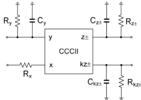
With regards to the effect of parasitic parameters, it can be evaluated using the non-ideal CCCII symbol as
Fig. 6. Simplified equivalent circuit of the non-ideal CCCII.
X ωo x S Q x S Rx1 -0.5 0.5 Rx2 -0.5 -0.5 1 C -0.5 0.5 2 C -0.5 -0.5 1 0.5 -0.5 2 0.5 0.5 1 0.5 0.5 2 0.5 0.5 k1 0.0 -1.0 k1 0.0 -1.0
Tab. 2. Sensitivities of circuit components.
shown in Fig. 6. Typically, Ry, Rz and Rzk possess high
value parasitic resistance while Cy, Cz and Czk possess
low parasitic capacitance. Using (13) and taking into account the non-ideal CCCII characteristics as shown in Fig. 6, the modified demonstrate D(s) of (4)-(8) can be expressed as 2 1 1 1 1 2 1 2 1 2 2 ( ) s k s D s k n n
n
(14) where 1 1 1 1 1 x s n R C s
, (15) 2 2 2 2 1 x s n R C s
, (16) 1 1 1 1 n R C , 2 2 2 1 n R C
, C1 C1Cy1Ck z1 1-Cz2-, 2 2 y2 z1 C C C C , Rn1Ry1/ /Rk z1 1-/ /Rz2-, 2 2/ / 1 n y zR R R . Form (14)-(16), the effect of the para-sitic parameters of CCCII are dependent on two parapara-sitic poles. The frequency of operation should be larger than ω1
and ω2 for close to ideal operation at high frequency. Using
PSPICE simulations, the parasitic elements of the CCCII for Io= 32 µA can be calculated as Cy1 = Cy2= 2.2 pF,
Cz1+ = Cz2- 1.67 pF, Ck1z1- = 1.1 pF, Ry1= Ry2 = 358 k,
Rz2- = 350 k, Rz1+ = 366 k, and Rk1z1-= 151 k For
example, if the proposed filter was designed for fo = 1 MHz
by choosing C1 = C2 = 0.4 nF and Rx1 = Rx2 394 , then
7.5 kHz and f2 will be located at approximately 2.1 kHz.
Thus, the ideal operation of the filter will be valid for frequencies higher than approximately 10f1 [9], [10].
Assume that ω1 and ω2 » 1, the parameters o and Q can be
rewritten by 1 2 1 2 1 2 1 2 o x x R R C C
, (17) 1 1 2 1 2 1 1 2 2 1 1 x k x R C Q k R C
. (18)From (17) and (18), the tracking errors slightly change the natural frequency and the quality factor. How-ever, the parameters o and Q can still be orthogonally
controllable. The incremental sensitivities of the parame-ters o and Q are calculated in Tab. 2. It can be indicated
that the sensitivities of the proposed filter are low.
4.
Simulation Results
In order to verify the characteristics of the proposed filter in Fig. 5, PSPICE simulators were carried out. The CCCIIs were performed with the transistor model of HFA3046 as listed in Tab. 3 and the DC supply voltage VCC = -VEE = 3 V. When the ECCCII in Fig. 3 was
simu-lated by PSPICE simulators, the parameters = 0.998,
+ = 0.995 and - = 1.065 were obtained and other
simu-lated results were presented in Tab. 4. The frequency re-sponse of the ECCCII with different bias current Ia of 50,
250, 500, 700 to 1000 μA was investigated and shown in Fig. 7. As an example design, C1 = C2 = 0.4 nF was given.
Fig. 8 shows the simulated frequency responses of the filter with Io1 = Io2 = 32 A and Ia1 = Ib1 = 50 A. This setting
was designed to obtain the LP, BP, HP and BS filter re-sponses with fo 1.02 MHz and Q = 1. Fig. 9 shows the
simulated frequency responses of the gain and phase char-acteristics of the AP filter at fo 1 MHz. It was clear from
both figures that the proposed filter performs five standard biquadratic filtering functions well. In Figs. 8 and 9, the pole frequency of 1 MHz was obtained. The pole fre-quency was 1 MHz instead of 1.02 MHz owing to the effect of non-ideal CCCIIs. Fig. 10 shows the simulated BP filter response when the DC bias currents Io (i.e.
Io = Io1 = Io2) were simultaneously adjusted for the values
15, 25, 40 and 60 A, respectively, while keeping Ia1 = Ib1 = 50 A for Q = 1. This result was confirmed by
(9). To demonstrate the current gain of current conveyor tuning of Q, the bias currents were set to be constant at Io1 = Io2 = 32 A and Ia1 = 50 A. Fig. 11 shows the
corre-sponding current characteristics of the BP filter when Ib1
was varied. It is obvious that high values of the Q can be easily obtained from high ratios of current gain as was confirmed by (12). From Figs. 8 to 11 it is evident that the simulation results agree quite well with the theoretical analysis. Therefore, the proposed filter easily obtains sepa-rate electronic control of parameter o and Q and high-Q
value filter by using ECCCII. Recently, a new active de-vice, so-called double current controlled current feedback amplifier (DCC-CFA) was proposed [51], [52]. This device provides the current gain that can be used to realize the filter with separate control of parameter o and Q and
high-Q value. However, this DCC-CFA was realized using bi-polar and CMOS technologies and thus BiCMOS technol-ogy was needed for integrated circuit implementation which is difficult as a fabrication process.
.model NUHFARRY NPN (IS=1.840E-16 XTI=3.000E+00 EG=1.110E+00 VAF=7.200E+01 VAR= 4.500E+00 BF=1.036E+02 ISE=1.686E-19 NE=1.400E+00 IKF= 5.400E-02 XTB=0.000E+00 BR= 1.000E+01 ISC=1.605E-14 NC=1.800E+00 IKR=5.400E-02 RC=1.140E+01 CJC=3.980E-13 MJC= 2.400E-01 VJC=9.700E-01 FC=5.000E-01 CJE=2.400E-13 MJE=5.100E-01 VJE=8.690E-01 TR=4.000E-09 TF=10.51E-12 ITF=3.500E-02 XTF=2.300E+00 VTF=3.500E+00 PTF=0.000E+00 XCJC=9.000E-01 CJS=1.150E-13 VJS=7.500E-01 MJS=0.000E+00 RE=1.848E+00 RB=5.007E+01 RBM=1.974E+00 KF=0.000E+00 AF=1.000E+00)
.model PUHFARRY PNP (IS=1.027E-16 XTI=3.000E+00 EG=1.110E+00 VAF=3.000E+01 VAR=4.500E+00 BF=5.228E+01 ISE=9.398E-20 NE=1.400E+0 IKF=5.412E-02 XTB=0.000E+00 BR= 7.000E+00 ISC=1.027E-14 NC=1.800E+00 IKR=5.412E-02 RC=3.420E+01 CJC=4.951E-13 MJC=3.000E-01 VJC=1.230E+00 FC=5.000E-01 CJE=2.927E-13 MJE=5.700E-01 VJE=8.800E-01 TR=4.000E-09 TF=20.05E-12 ITF=2.001E-02 XTF=1.534E+00 VTF= 1.800E+00 PTF=0.000E+00 XCJC=9.000E-01 CJS=1.150E-13 VJS=7.500E-01 MJS=0.000E+00 RE=1.848E+00 RB=3.271E+01 RBM=9.902E-01 KF=0.000E+00 AF=1.000E+00)
Tab. 3. Parameter of HFA3046 transistor array.
Parameters Value
Power supply 3 V
DC voltage range -2 to 2 V Voltage error range <7 mV DC current range -25 to 25 mA Bandwidth (-3dB) @ [Io= 50 µA, Ia= 50 µA, Ib= 50 µA] Voltage follower (Vx/Vy) Current follower (Iz/Ix) Current follower (Izk/Ix) 370 MHz 177 MHz 112 MHz Rx, Lx @ [Io =50 µA] 253 , 0.73 µH Ry, Cy 358 k, 2.2 pF Rz+, Cz+ Rzk, Czk @ [Ia=Ib=50 µA] Rzk, Czk @ [Ia=1000 µA, Ib=50 µA] Rzk, Czk @ [Ia=50 µA, Ib=1000 µA] 366 k, 1.67 pF 150 k, 1.19 pF 13.59 k, 0.39 pF 3.6 M, 0.23 pF
Tab. 4. Simulated specifications of CCCII used.
In order to test the time-domain of the proposed filter, a LP filter at 1 MHz of cut-off frequency was simulated. In this case, a 100 kHz in-band of LP filter was selected. Fig. 12 shows the time domain responses for LP filter when a 100 kHz sinusoidal input current with 100 A peak was applied to the filter. It was observed that 100 A peak
0.01 0.1 1.0 10 100 1000 -60 -40 -20 0 20 40 Ia=50 A Ia=700 A Ia=500 A Ia=250 A Ia=1000 A Frequency, MHz
Fig. 7. Simulated response of current gain k.
Fig. 8. Simulated LP, BP, HP and BS of the proposed filter.
Fig. 9. Simulated AP response of the proposed filter.
0.0001 0.001 0.01 0.1 1.0 10 100 -80 -60 -40 -20 0 20 Gain, d B Frequency, MHz Simulated (Q=1) Io=15 A Io=60 A Io=40 A Io=25 A Theoretical (Q=1) Io=15 A Io=25 A Io=40 A Io=60 A
Fig. 10. Simulated frequency responses of the BP filter when Io
is varied. 0.01 0.1 1.0 10 100 -80 -60 -40 -20 0 20 Frequency, MHz Ga in , d B Simulated Ib1=250 A Ib1=1000 A Ib1=700 A Ib1=500 A Theoretical Ib1=250 A Ib1=500 A Ib1=700 A Ib1=1000 A Q 5 10 14 20 Q 5 10 14 20
Fig. 11. Simulated frequency responses of the BP filter when Ib1 is varied.
Fig. 12. Time-domain input and output signal waveforms to demonstrate the dynamic range of the proposed filter.
THD
,
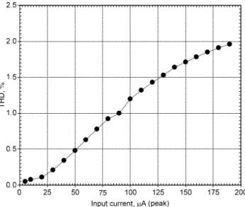
Fig. 13. Dependence of the output harmonic distortion of LP filter on input current amplitude.
Fig. 14. Simulated power consumption when the quality factor is varied using the bias current.
input signal current level was possible without significant distortion. The result of the ILP total harmonic distortion
(THD) analysis was approximately 1.2 %. The harmonic distortion increases rapidly if the input signal was in-creased beyond 200 A peak. The dependence of the THD of LP filter on input current amplitude was shown in Fig. 13. The THD was about 1.96 % when the input signal was increased to 190 µA (peak). The power consumption of the proposed filter with different natural frequencies fo
(0.1 MHz, 1 MHz and 10 MHz) when the quality factor was varied using the bias current, was investigated. Fig. 14 shows the power consumption of the circuit with the bias current Io of 3.1 µA (fo = 0.1 MHz), 32 µA (fo = 1 MHz)
and 340 µA (fo = 100 MHz) when the quality factor was
varied from 1 to 20 using the bias current Ib2 from
50 (Q = 1) to 1000 µA (Q = 20) while constant Ib1 = 50 µA.
The THD for different values of Q was also investigated. The simulated result was reported that for Q of 1, 3, 5 and 10, the THDs were 1.28, 2.4, 2.4, and 3.2 % for the input signals of 50, 30, 20 and 10 µA peak, respectively.
5.
Conclusions
A new four inputs and five outputs electronically tun-able current-mode universal biquad filter employing only one CCCII and one ECCCII and two grounded capacitors was proposed. The use of grounded capacitor and absence from any resistors makes the proposed filter ideal for inte-grated circuit implementation. In addition, a new single input and five outputs can be achieved by using an addi-tional CCCII to obtain four plus input currents. The pro-posed circuit possesses the following properties: (1) employment of three translinear current conveyors; (2) ability of realizing all the five standard biquadratic filtering functions, i.e. LP, BP, HP, BS and AP filters with one single topology, (3) separate electronic control of the parameters o and Q, (4) employment of all grounded
capacitors, (5) no need to impose critical-matching condi-tion for realizing all the filter responses; (6) provision of low-input impedance, high-output impedance and low active and passive sensitivities and especially (7) offer of electronically tunable high Q-value filter. Simulation results are also given to demonstrate the effectiveness of our schemes. The simulation results obtained were found to be in good agreement with the theory.
Acknowledgements
This work was supported by King Mongkut’s Institute of Technology Ladkrabang (KMITL) (KMITL Research Fund to S. Tungjitkusolmun, M. Kumngern, P. Phasukkit) and by the SIX project; the registration number CZ.1.05/2.1.00/03.0072, the operational program Research and Development for Innovation and has been supported by the Czech Science Foundation project No.: P102-14-07724S.
References
[1] ROBERTS, G. W., SEDRA, A. S. All-current-mode frequency selective circuits. Electronics Letters, 1989, vol. 25, p. 759-761. [2] TOUMAZOU, C., LIDGEY, F., MAKRIS C. A. Extending
voltage-mode op amps to current-mode performance. IEE Proceeding Part-G, 1990, vol. 137, p. 116-130.
[3] CHANG, C. M. Universal active current filter with single input and three outputs using CCIIs. Electronics Letters, 1993, vol. 29, p. 1932-1933.
[4] OZOGUZ, S., ACAR, C. Universal current-mode filter with reduced number of active and passive components. Electronics Letters, 1997, vol. 33, p. 948-949.
[5] SENANI, R. New current-mode biquad filter. International Journal of Electronics, 1992, vol. 73, p. 735-742.
[6] HORNG, J. W., HOU, C. L., CHANG, C. M., SHIE, J. Y., CHANG, C. M. Universal current filter with single input and three outputs using MOCCIIs. International Journal of Electronics, 2007, vol. 94, p. 327-333.
[7] WANG, H. Y., LEE, C. T. Versatile insensitive current-mode universal biquad implementation using current conveyors. IEEE Trans. on Circuits and Systems-II, 2001, vol. 48, p. 409–413. [8] TOKER, A., OZOGUZ, S. Insensitive current-mode universal
filter using dual output current conveyors. International Journal of Electronics, 2000, vol. 87, p. 667-674.
[9] CHEN, H.-P. Versatile current-mode universal biquadratic filter using DO-CCIIs. International Journal of Electronics, 2013, vol. 100, p.1010-1030.
[10] FABRE, A., SAAID, O., WIEST, F., BOUCHERON, C. Current controlled bandpass filter based on translinear conveyors. Electronics Letters, 1995, vol. 31, p. 1727-1728.
[11] TANGSRIRAT, W. SURAKAMPONTORN, W. Electronically tunable current-mode universal filter employing only plus-type current-controlled conveyors and grounded capacitors. Circuits, Systems & Signal Processing, 2006, vol. 25, p. 701-713.
[12] TANGSRIRAT, W. Current-tunable current-mode multifunction filter based on dual-output current-controlled conveyors. International Journal of Electronics and Communications, 2007, vol. 61, p. 528-533.
[13] TANGSRIRAT, W., SURAKAMPONTORN, W. High output impedance current-mode universal filter employing dual-output current-controlled conveyors and grounded capacitors. International Journal of Electronics and Communications, 2007, vol. 61, p. 127-131.
[14] TSUKUTANI, T., SUMI, Y., YABUKI, N. Versatile current-mode biquadratic circuit using only plus type CCCIIs and grounded capacitors. International Journal of Electronics, 2007, vol. 94, p. 1147-1156.
[15] KUMNGERN, M., JONGCHANACHAVAWAT, W., DEJHAN, K. New electronically tunable current-mode universal biquad filter using translinear current conveyors. International Journal of Electronics, 2010, vol. 97, p. 511-523.
[16] YUCE, E., KIRCAY, A., TOKAT, S. Universal resistorless current-mode filters employing CCCIIs. International Journal of Circuit Theory and Applications, 2008, vol. 36, p. 739–755. [17] KUMNGERN, M. Multiple-input single-output current-mode
universal filter using translinear current conveyors. Journal of Electrical and Electronics Engineering Research, 2011, vol. 3, p. 162-170.
[18] FABRE, A., SAAID, O., WIEST, F., BOUCHERON, C. High frequency applications based on a new current controlled conveyor. IEEE Transactions on Circuits and System-I, 1996, vol. 43, p. 82-91.
[19] KIRANON, W., KESORN, J., SANGPISIT, W., KAMPRASERT, N. Electronically tunable multifunctional translinear-C filter and oscillator. Electronics Letters, 1997, vol. 33, p. 573-574.
[20] ABUELMA’ATTI, M. T., TASADDUQ, N. A. A novel single-input multiple-output current-mode current-controlled universal filter. Microelectronics Journal, 1998, vol. 29, p. 901-905. [21] ABUELMA’ATTI, M. T., TASADDUQ, N. A. New current-mode
current-controlled filters using the current controlled conveyor. International Journal of Electronics, 1998, vol. 85, p. 483-488. [22] ABUELMA'ATTI, M. T, TASADDUQ, N. A. Universal
current-controlled current-mode filter using the multiple-output translinear current conveyor. Frequenz, 1998, vol. 52, p. 252-254.
[23] KHAN, I. A., ZAIDI, M. H. Multifunctional translinear-C current-mode filter. International Journal of Electronics, 2000, vol. 87, p. 1047-1051.
[24] MINAEI, S., TURKOZ, S. New current-mode current-controlled universal filter with single input and three outputs. International Journal of Electronics, 2001, vol. 88, p. 333-337.
[25] ABUELMA’ATTI, M. T. A novel mixed-mode current-controlled current-conveyor-based filter. Active and Passive Electronics Components, 2003, vol. 26, p. 185-191.
[26] MINAEI, S., TURKOZ, S. Current-mode electronically tunable universal filter using only plus-type current controlled conveyors and grounded capacitors. ETRI Journal, 2004, vol. 26, p. 292-296. [27] SAGBAS, M., FIDANBOYLU, K. Electronically tunable current-mode second-order universal filter using minimum elements. Electronics Letters, 2004, vol. 40, p. 2-4.
[28] PANDEY, N., PAUL, S. K., BHATTACHARYYA, A., JAIN, A. B. A novel current controlled current mode universal filter: SITO approach. IEICE Electronics Express, 2005, vol. 2, p. 451-457. [29] SHAH, N. A., RATHER, M. F., IQBAL, S. Z. SITO electronically
tunable high output impedance current-mode universal filter. Analog Integrated Circuits and Signal Processing, 2006, vol. 47, p. 335-338.
[30] MINAEI, S., YUCE, E. Universal current-mode active-C filters employing only plus-type current controlled conveyors. Frequenz, 2006, vol. 60, p. 134-137.
[31] MINAEI, S., YUCE, E. Current-mode active-C filters employing reduced number of CCCII+s. Journal of Circuits, Systems and Computers, 2007, vol. 16, p. 507-516.
[32] YUCE, E., MINAEI, S. On the realization of high-order current-mode filter employing current controlled conveyors. Computer and Electrical Engineering, 2008, vol. 34, p. 165-172.
[33] WANG, C., LIU, H., ZHAO, Y. A new mode current-controlled universal filter based on CCCII(±). Circuits, Systems and Signal Processing, 2008, vol. 27, p. 673-682.
[34] SIRIPRUCHYANUN, M., JAIKLA, W. Cascadable current-mode biquad filter and quadrature oscillator using DO-CCCIIs and OTA. Circuits, Systems & Signal Processing, 2009, vol. 28, p. 99-110. [35] YUCE, E. Current-mode electronically tunable biquadratic filters
consisting of only CCCIIs and grounded capacitors. Microelectronics Journal, 2009, vol. 40, p. 1719-1725.
[36] ZHIJUN, L. Mixed-mode universal filter using MCCCII. International Journal of Electronics and Communications, 2009, vol. 63, p. 1072-1075.
[37] PANDEY, N., PAUL, S., JAIN, S. B. A new electronically tunable current mode universal filter using MO-CCCII. Analog Integrated Circuits and Signal Processing, 2009, vol. 58, p. 171-178. [38] JERABEK, J., VRBA, K. SIMO type low-input and high-output
impedance current-mode universal filter employing three universal current conveyors. International Journal of Electronics and Communications, 2010, vol. 64, p. 588–593.
[39] SOTNER, R., SLEZAK, J., DOSTAL, T., PETRZELA, J. Universal tunable current-mode biquad employing distributed feedback structure with MO-CCCII. Journal of Electrical Engineering, 2010, vol. 61, p. 52-56.
[40] WANG, C., XU, J., KESKIN, A. U., DU, S., ZHANG, Q. A new current-mode current-controlled SIMO-type universal filter. International Journal of Electronics and Communications, 2011, vol. 65, p. 231-234.
[41] KUMNGERN, M. A new current-mode universal filter with single-input five-output using translinear current conveyors. Australian Journal of Electrical & Electronics Engineering, 2012, vol. 9, p. 177-184.
[42] KUMNGERN, M., MOUNGNOUL, P., JUNNAPIYA, S., DEJHAN, K. Current-mode universal filter using translinear cur-rent conveyors. In Proceedings of 5th International Conference on Electrical Engineering/Electronics, Computer, Telecommunica-tions and Information Technology (ECTI-CON 2008). Thailand, 2008, p. 717-720.
[43] YUCE, E., METIN, B., CICEKOGLU, O. Current-mode biquadratic filters using single CCIII and minimum numbers of passive elements. Frequenz, 2004, vol. 58, p. 225–228.
[44] TOUMAZOU, C., LIDGEY, F. J., HAIG, D. G. Analogue IC Design: The Current-Mode Approach. Peter Peregrinus, 1990. [45] ABUELMA’ATTI, M. T., AL-QAHTANI, M. A. A new
current-controlled multiphase sinusoidal oscillator using translinear current conveyor. IEEE Transactions on Circuits and Systems–II, 1998, vol. 45, p. 881-885.
[46] FABRE, A., MIMECHE, N. Class A/AB second generation current conveyor with controlled current gain. Electronics Letters, 1996, vol. 43, p. 82-91.
[47] SURAKAMPONTORN, W., KUMWACHARA, K. CMOS-based electronically tunable current conveyor. Electronics Letters, 1992, vol. 28, p. 1316-1317.
[48] MINAEI, S., SAYIN, O. K., KUNTMAN, H. A new CMOS elec-tronically tunable current conveyor and its application to current-mode filters. IEEE Transactions on Circuits and Systems–I, 2006, vol. 53, p. 1448-1457.
[49] BHUSAN, M., NEWCOMB, R. W. Grounding of capacitors in integrated circuits. Electronics Letters, 1967, vol. 3, p. 148–189. [50] SENANI, R. Novel lossless synthetic floating inductor employing
a grounded capacitor. Electronics Letters, 1982, vol. 18, p. 413 to 414.
[51] SOTNER, R., JERABEK, J., HERENCSAR, N., DOSTAL, T., VRBA, K. Electronically adjustable modification of CFA: double current controlled CFA (DCC-CFA). In Proceedings of the 35th International Conference on Telecommunications and Signal Processing (TSP 2012). Czech Republic, 2012, p. 401–405. [52] SOTNER, R., HERENCSAR, N., JERABEK, J., DVORAK, R.,
KARTCI, T., DOSTAL, T., VRBA, K. Double current controlled CFA (DCC-CFA) based voltage-mode oscillator with independent electronic control of oscillation condition and frequency. Journal of Electrical Engineering, 2013, vol. 64, p. 65–75.
About Authors …
Montree KUMNGERN received the B.S.Ind.Ed. degree from King Mongkut’s University of Technology Thonburi (KMUTT), Bangkok, Thailand, in 1998, the M.Eng. and D.Eng. degrees from King Mongkut’s Institute of Tech-nology Ladkrabang (KMITL), Bangkok, Thailand, in 2002 and 2006, respectively, all in major of Electrical Engi-neering. He is currently Assistant Professor at the Faculty of Engineering, KMITL. His research interests include
analog electronics, analog and digital VLSI circuits and nonlinear electronic circuits.
Fabian KHATEB was born in 1976. He received the M.Sc. and Ph.D. degrees in Electrical Engineering and Communication and also in Business and Management from Brno University of Technology, Czech Republic in 2002, 2005, 2003 and 2007, respectively. He is currently Associate professor at the Department of Microelectronics, Brno University of Technology. He has expertise in new principles of designing analog circuits, particularly low voltage low-power applications. He is author or co-author of more than 75 publications in journals and proceedings of international conferences.
Pattarapong PHASUKKIT was born in Saraburi, Thai-land, on May 18, 1978. He received the B.Eng. and M.Eng. degrees in Telecommunications Engineering in 2000 and 2003, respectively, and D.Eng. degree in Electrical Engi-neering in 2011 from King Mongkut’s Institute of Tech-nology Ladkrabang (KMITL), Bangkok, Thailand. Since 2011, he has been with the Faculty of Engineering, KMITL as a member of the Department of Electronics, KMITL. His current research interests include microwave ablation, antenna design, and wireless communications.
Supan TUNGJITKUSOLMUN was born in Bangkok, Thailand, on December 5, 1972. He received the B.S.E.E. degree from the University of Pennsylvania, Philadelphia, in 1995, and the M.S.E.E. and Ph.D. degrees from the University of Wisconsin, Madison, in 1996 and 2000, respectively. From 2003 to 2007, he was the Assistant Director of Computer Research and Service Center, King Mongkut’s Institute of Technology Ladkrabang, Bangkok, Thailand, where he is currently an Assistant Professor with the Faculty of Engineering, Department of Electronics. His current research interests include finite-element modeling, radio frequency ablation, microwave ablation, signal processing, and image processing.
Somyot JUNNAPIYA received the B.Ind.Tech. and M.Eng. degree in Electrical Engineering from The King Mongkut’s Institute of Technology Ladkrabang (KMITL), Bangkok, THAILAND, in 1982 and 1987, respectively. Since 1982, he has been a member of the Department of Telecommunication, Faculty of Engineering, KMITL, where he is currently an associate professor of telecommu-nication. His research interests include analog circuit de-sign and microcontroller application.