Filters with Multi-Loop Feedback Structure
in Current Mode
Tomáš DOSTÁL
Dept. of Radio Electronics, Brno University of Technology, Purkyňova 118, 612 00 Brno, Czech Republic [email protected]
Abstract. Universal multifunctional (low-pass, high-pass, band-pass, band-reject and all-pass) nth-order active RC
filters in current mode are presented in this paper. The filters are based on several multi-loop feedback and state-variable structures. Their modification and implementation using multi-output transconductors (OTA) and current followers are given.
Keywords
Analogue circuits, filters, current mode, state-variable based structures.
1. Introduction
Continuous-time active filters in current mode have found applications in many areas audio, video and com-munication systems. New active devices and functional blocks are there used, such as transadmittance amplifiers (OTA), current conveyors, current amplifiers and followers (CF) etc. Many novel filter structures have been proposed and or classical filters based on the opamps have been modified. In recent years the OTA-C filters have received particular interest by Sun, Y., Fidler J. K., Acar, C., Anday, F., Kuntman, H. and others [1], [7], [8], [9].
Current mode (CM) is known [3], which is inherent in simplicity implementing such operations as addition (cur-rent summation), subtraction, integration and multiplication by constant. There can be also used simple current replicas (current distribution) and multiple outputs independent of other loading. It is well known, that these circuits can operate at much higher frequencies than the techniques in standard voltage mode with the opamp’s.
Classical state variable model (using signal flow graph) of the universal multifunctional (low-pass, high-pass, band-high-pass, band-reject and all-pass) nth-order filter in standard voltage mode is there modified and transformed to the CM and non-conventionally realized. These filters have an advantage over the cascade and ladder structures, na-mely in universality of function, simplicity in direct design and independently adjustable coefficients.
2. Canonical State-Variable
Multi-Loop Structures in Current Mode
The current transfer function of any nth-order filter can be generally expressed as0 1 1 1 0 1 1 1 ... ... b s b s b s a s a s a s a I I K n n n n n n n inp out + + + + + + + + = = − − − − . (1)
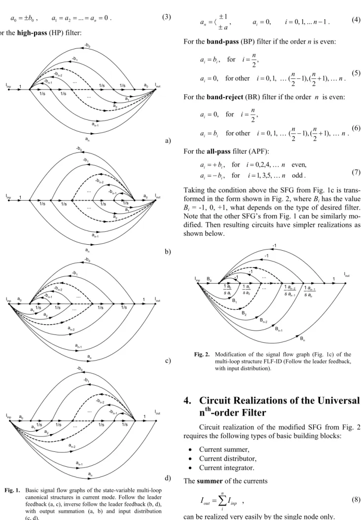
State-variable multi-loop structure (MLS) corresponding with the formula (1) in classical voltage mode (VM) is well-known [1], [2]. Usually as an acceptable model of the MLS the signal flow graph (SFG) is used [1]. These VM-SFG can be transformed to the CM using the adjoint VM → CM transformation from [3] to obtain the desired current SFG. Four CM-SFG’s of the basic canonical MLS’s in CM are shown in Fig. 1. There are namely the follow the leader feedback (FLF) structure (Fig. 1a, Fig. 1c) and the inverse follow the leader feedback (IFLF) structure (Fig. 1b, Fig. 1d), with the output summation (OS) (Fig. 1a, Fig. 1b) and with the input distribution (ID) (Fig. 1c, Fig. 1d). All these MLS’s from Fig. 1 can be di-rectly implemented using current integrators, current am-plifiers (multipliers by constant), current summers and current distributors, what is a little complicated and it is the reason of following modification.
3. Modification of Multi-Loop
Structures
MLS structures given in Fig. 1 can be ingeniously modified for the real universal multifunctional nth-order filter as follows. Firstly the denominator of the transfer function (1) keeps the form, but the numerator has a simp-ler and concrete design with the following coefficients only
, for 0 1 , 1 ... , 1 , 0 for 0 n i a a n i b b a i i i i ± = ± 〈 = − = − + 〈 = (2)
what depends on the desired type of this filter. Note that a
in (2) is a real number.
. 0 ... , 1 2 0 0 =±b a =a = =an= a (3)
For the high-pass (HP) filter: -b1 -b0 -bn-1 a1 1/s a2 1/s 1 Iinp 1/s 1/s a0 Iout -bn-2 an an-1 ... ... a) -b1 -b0 -bn-1 a1 1/s a2 1/s 1 Iinp a0 Iout 1/s 1/s -bn-2 an an-1 ... ... b) -b1 -b0 -bn-1 a11/s a2 1/s 1 Iinp a0 Iout 1/s 1/s -bn-2 an an-1 ... ... an-2 c) Iout a11/s a2 1/s 1 a0 1/s 1/s an an-1 ... an-2 -b1 -b0 -bn-1 -bn-2 ... Iinp d)
Fig. 1. Basic signal flow graphs of the state-variable multi-loop canonical structures in current mode. Follow the leader feedback (a, c), inverse follow the leader feedback (b, d), with output summation (a, b) and input distribution (c, d). . 1 ... , 1 , 0 , 0 , 1 − = = ± ± 〈 = a i n a an i (4)
For the band-pass (BP) filter if the order n is even:
. ), 1 2 ( ), 1 2 ( , 1 , 0 other for , 0 , 2 for , n n n i a n i b a i i i K K − + = = = = (5) For the band-reject (BR) filter if the order n is even:
. ), 1 2 ( ), 1 2 ( , 1 , 0 other for , 2 for , 0 n n n i b a n i a i i i K K − + = = = = (6) For the all-pass filter (APF):
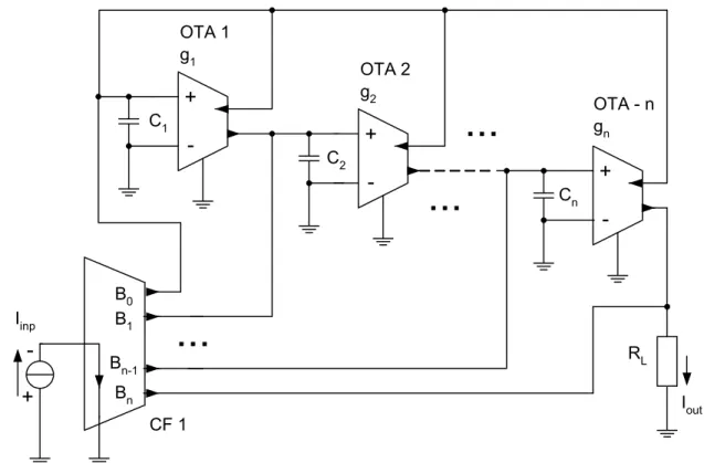
. odd , 5 , 3 , 1 for , , even , 4 , 2 , 0 for , n i b a n i b a i i i i K K = − = = + = (7) Taking the condition above the SFG from Fig. 1c is trans-formed in the form shown in Fig. 2, where Bi has the value
Bi= -1, 0, +1, what depends on the type of desired filter. Note that the other SFG’s from Fig. 1 can be similarly mo-dified. Then resulting circuits have simpler realizations as shown below. 2 1 1 a a s 1 0 1 a a s Iinp Iout B1 B2 1 B0 Bn Bn-1 ... Bn-2 -1 -1 -1 -1 ... 1 2 1 − − n n a a s 1 1 − n n a a s
Fig. 2. Modification of the signal flow graph (Fig. 1c) of the multi-loop structure FLF-ID (Follow the leader feedback, with input distribution).
4. Circuit Realizations of the Universal
n
th-order Filter
Circuit realization of the modified SFG from Fig. 2 requires the following types of basic building blocks:
• Current summer, • Current distributor, • Current integrator. The summer of the currents
,
∑
= n i inp out I I (8)+
-
+
-
+
-+
-C1 RL Iout Iinp B0 Bn-1 B1 Bn CF 1 OTA - n gn OTA 1 g1 OTA 2 g2 C2...
...
...
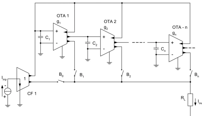
CnFig. 3. Circuit diagram of the current mode nth-order universal filter based on the follow the leader feedback multi-loop structure with input distribution (FLF-ID), corresponding with the signal flow graph given in Fig.2 (Fig. 1c).
+
-
+
-
+
-+
-C1 RL Iout Iinp B0 Bn-1 B1 Bn 1 CF 1 CF 2 OTA - n gn OTA 1 g1 OTA 2 g2 C2...
...
...
Cn...
Fig. 4. Circuit diagram of the current mode nth-order universal filter based on the inverse follow the leader feedback multi-loop structure with input distribution (IFLF-ID, Fig. 1d)
The current integrator with the transfer function
, 1 + = = n n inp out i a a s 1 I I K (9)
can be implemented by single-input double-output (SIDO) transconductor (OTA) and capacitor (OTA-C). There (Fig. 3) are two current replicas with opposite phase required at the output of integrators in the case of the FLF-ID (Fig. 2). Noting that, for the structure FLF-OS three current replicas are needful, as shown below (Fig. 5).
+
-RL Iout OTA - n gn Cn+
-OTA 2 g2 C2+
-OTA 1 g1 C1 B0 B1 B2 Bn+
-Iinp CF 1 1Fig. 5. Circuit diagram of the current mode nth-order universal filter based on the follow the leader feedback multi-loop structure with output
summation(FLF-OS, Fig. 1a).
+
-+
-+
-C1 1 CF 2 OTA - n gn OTA 1 g1 OTA 2 g2 C2...
...
Cn RL B0 B1 B2 Bn+
-Iinp CF 1 1 IoutFig. 6. Circuit diagram of the current mode nth-order universal filter based on the inverse follow the leader feedback multi-loop structure with
output summation(IFLF-OS, Fig. 1b).
The current distributor (first node of the SFG in Fig. 2) is realized by the single-input multi-output (SIMO) current follower (CF 1 in Fig. 3). The CF1 is producing (n+1) current replicas of the input current, to obtain the designed type of the filter. The resulting circuit diagram of the structure FLF-ID (the SFG in Fig. 1c and after modifi-cation in Fig. 2) is shown in Fig. 3.
Similarly the structure IFLF-ID (the SFG in Fig. 1d) can be realized using the same way, to obtain the circuit diagram of the nth-order universal filter in Fig. 4. There are simpler OTA’s, namely the SISO type (instead of the SIDO in Fig. 3), but two current followers are needed (CF 1 and CF 2 in Fig. 4).
Parameters of CF 1
Modification Transfer function Type of filter
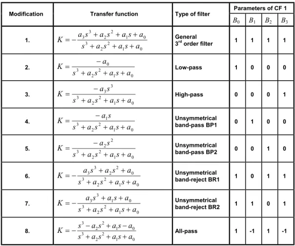
B0 B1 B2 B3 1. 0 1 2 2 3 0 1 2 2 3 3 a s a s a s a s a s a s a K + + + + + + − = General 3rd order filter 1 1 1 1 2. 0 1 2 2 3 0 a s a s a s a K + + + − = Low-pass 1 0 0 0 3. 0 1 2 2 3 3 3 a s a s a s s a K + + + − = High-pass 0 0 0 1 4. 0 1 2 2 3 1 a s a s a s s a K + + + − = Unsymmetrical band-pass BP1 0 1 0 0 5. 0 1 2 2 3 2 2 a s a s a s s a K + + + − = Unsymmetrical band-pass BP2 0 0 1 0 6. 0 1 2 2 3 0 2 2 3 3 a s a s a s a s a s a K + + + + + − = Unsymmetrical band-reject BR1 1 0 1 1 7. 0 1 2 2 3 0 1 3 3 a s a s a s a s a s a K + + + + + − = Unsymmetrical band-reject BR2 1 1 0 1 8. 0 1 2 2 3 0 1 2 2 3 a s a s a s a s a s a s K + + + − + − − = All-pass 1 -1 1 -1
Tab. 1. Modifications of the given universal 3rd-order filter (Fig. 4).
The resulting circuit diagram of the nth-order universal filter based on the structure FLF-OS (Fig. 1a) is shown in Fig. 5 and on the IFLF-OS (Fig. 1b) is in Fig. 6 respective-ly. The switches (Bn) determine there a type of designed filter, summing some output currents, what is a dual func-tion of the CF 1 in the structure with input current distri-bution (Fig. 3 and Fig. 4).
5. Illustrative Example
of the Universal 3
rd-order Filter
To illustrate the given IFLF-ID structure in CM (Fig. 4), a universal (LP, HP, BP, BR, APF) 3rd-order video filter is designed with the following specification:• The cut-off and center frequency are
fc = fo = 1 MHz,
• For the pass-band with Kc = - 3 dB, • The stop-band frequency is fs =3 MHz, • For the minimum Ks = - 35 dB and • Butterworth approximation.
In the first step the following coefficients of the desired transfer function (1) are obtained using the filter design computer tool NAFID [5]:
a0 = 2.48640 ⋅ 1020 ,
a1 = 7.90819 ⋅ 1013 , (10)
a2 = 1.25763 ⋅ 107 ,
a3 = 1 .
The circuit diagram of this filter given in Fig. 4 consists of three OTA-SISO with parameters g1, g2, g3, three capaci-tors (C1, C2, C3), and two current followers CF-SIMO with four outputs (CF1, CF2).
This circuit (Fig. 4) has been symbolically analyzed by SNAP [6] to obtained the following denominator
3 3 3 2 3 2 3 2 3 2 1 3 2 1 3 3 2 2 1 0 ) ( s C g s C C g g s C C C g g g a s a s sa a s D + + + = = + + + = . (11)
The resulting numerators for eight several modifications and the types of the 3rd-order filter are simply given by the configuration and the parameters Bi(1, -1, 0) of the block CF 1 (Fig. 4) as shown in detail in Tab. 1.
Following three design equations are obtained sub-stituting the desired coefficients ai (10) in the equation (11)
. 10 25763 . 1 , 10 90819 . 7 , 10 48640 . 2 7 3 3 2 13 3 2 3 2 1 20 3 2 1 3 2 1 0 ⋅ = = ⋅ = = ⋅ = = C g a C C g g a C C C g g g a (12)
Then choosing C1 = C2 = C3 = 100 pF the resulting values of transconductances are:
g1 = 314 µS ,
g2 = 628 µS , (13)
g3 = 1.26 mS .
A lot of transconductance amplifiers is commercially available these days. The LT 1228 has been chosen. Using this IC, it is possible to set the value of the transconductan-ces in the following range
> <
∈ S mS
gm 10µ ,10 , (14)
namely by DC current ISET, what gives the possibility to set or tune this filter easily.
The multi-output current followers (CF 1, CF 2) can be realized using the improved Wilson’s current mirrors and bipolar transistors, modifying circuit given in [4].
6. Simulation Results
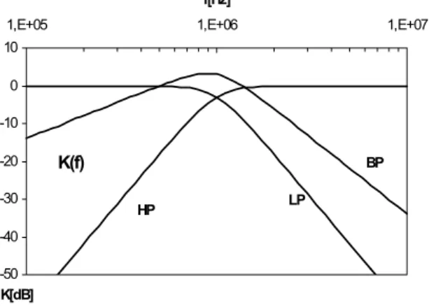
To verify the functionality of the proposed universal filter, the PSpice simulation has been carried out. Resulting magnitude responses for LP, HP and BP modification (Tab.1) of the universal 3rd-order filter (Fig. 4) are shown in Fig. 7. They have confirmed the symbolical analysis and theoretical assumptions. -50 -40 -30 -20 -10 0 10
1,E+05 1,E+06 1,E+07
f[Hz] K[dB] K(f) LP HP BP
Fig. 2. Magnitude responses of the given 3rd-order filter.
7. Conclusion
The SFG of the universal nth-order filter in standard state variable based voltage form is modified and transfor-med to the current mode and realized by current OTA-C
integrators and multi-output current followers. This filter has advantage in universality of the type or function and simplicity in direct design. Note that similar circuit struc-tures can be obtained using current conveyors instead of the transconductors (OTA) [10].
Acknowledgements
Research described in the paper was financially supported by the Czech Grant Agency under grant No. 102/01/022 and by the Czech Ministry of Education under research program CEZ J22/98: 262200011.
References
[1] CHEN, W.K. The circuits and filters handbook. Florida: CRC Press,
1995.
[2] BOWRON, P., STEPHENSON, F. W. Active filters for
communica-tions and instrumentation. London: McGraw-Hill, 1979.
[3] TOUMAZOU, C., LIDGEY, F. J., HAIGH, D. G. Analogue IC
de-sign: The current-mode approach. London: Peter Peregrinus Ltd.,
1990.
[4] MATSUMOTO, F., MIYAKE, NOGUCHI, Z. A high precision low-voltage bipolar current mirror circuit and its compensation for
stabi-lity. Internat. Journal of Electronics. 2000, vol. 87, no. 1, p. 71 – 78.
[5] HAJEK, K., SEDLACEK, J. NAFID program as powerful tool in
filter education area. In Proceedings of theConference CIBLIS’97.
Leicester (UK), 1997, p. PK-4 1-10.
[6] BIOLEK, D., KOLKA, Z., SVIEZENY, B. Teaching of electrical
circuits using symbolic and semisymbolic programs. In Proceedings
of the 11th ConferenceEAEEIE. Ulm (Germany), 2000, p. 26 – 30.
[7] SUN, Y., FIDLER, J. K. Current-mode OTA-C realization of
arbit-rary filter characteristics. Electronics Letters. 1996, vol. 32, no. 13,
p. 1181 – 1182.
[8] SUN, Y., FIDLER, J. K. Current-mode multiple-loop filters using
dual-output OTA’s and grounded capacitors. International Journal
of Circuit Theory and Application. 1997, vol. 25, no. 1, p. 69 – 80. [9] ACAR, C., ANDAY, F., KUNTMAN, H. On the realization of
OTA-C filters. International Journal of Circuit Theory and Application.
1993, vol. 21, no. 3, p. 331 – 341.
[10] DOSTAL, T. Realisation of Arbitrary Filter Characteristics Using
Current Conveyors. (will be published).
About Author...
Tomáš Dostál was born in Brno, Czech Republic, in 1943. He received the degrees of CSc. (Ph.D) and DrSc. in elec-trical engineering from Brno University of Technology in 1976 and 1989, respectively. From 1973 to 1978, and from 1980 to 1984, he was with the Military Academy in Brno, from 1978 to 1980 with the Military Technical College in Baghdad. Since 1984 he has been with Brno University of Technology, where he is now Professor of Radio-Electro-nics. His present interests are in circuit theory, analogue filters, switched capacitor networks and circuits in current mode.