Copyright © 2010, IGI Global. Copying or distributing in print or electronic forms without written permission of IGI Global is prohibited.
Keywords: Abstract Data Types (ADT), Design Frameworks, Formal Design Models, Software Engineering, System Architecture Specification, Unified Data Models (UDM), Unified Process Models (UPM)
INTRODUCTION
Computational operations can be classified into the categories of data object, behavior, and
resource modeling and manipulations. Based on this view, programs are perceived as a
co-ordination of the data objects and behaviors in computing. Data object modeling is a process to creatively extract and abstractly represent a real-world problem by data models based on the constraints of given computing resources.
Using types to model real-world entities can be traced back to the mathematical thought
The Formal Design Models
of a Set of Abstract
Data Types (ADTs)
Yingxu Wang, University of Calgary, Canada Xinming Tan, Wuhan University of Technology, China Cyprian F. Ngolah, Sentinel Trending & Diagnostics Ltd., Canada
Philip C.-Y. Sheu, University of California, Irvine, USA
ABSTRACT
Type theories are fundamental for underpinning data object modeling and system architectural design in computing and software engineering. Abstract Data Types (ADTs) are a set of highly generic and rigorously modeled data structures in type theory. ADTs also play a key role in Object-Oriented (OO) technologies for software system design and implementation. This paper presents a formal modeling methodology for ADTs using the Real-Time Process Algebra (RTPA), which allows both architectural and behavioral models of ADTs and complex data objects. Formal architectures, static behaviors, and dynamic behaviors of a set of ADTs are comparatively studied. The architectural models of the ADTs are created using RTPA architectural modeling methodologies known as the Unified Data Models (UDMs). The static behaviors of the ADTs are specified and refined by a set of Unified Process Models (UPMs) of RTPA. The dynamic behaviors of the ADTs are modeled by process dispatching technologies of RTPA. This work has been applied in a number of real-time and non-real-time system designs such as a Real-Time Operating System (RTOS+), a Cognitive Learning Engine (CLE), and the automatic code generator based on RTPA.
of Bertrand Russell (Russell, 1903) and Georg Cantor in 1932 (Lipschutz & Lipson, 1997). A type is a category of variables that share a common property such as the kind of data, domain, and allowable operations. Types are an important logical property shared by data objects in programming (Cardelli & Wegner, 1985; Mitchell, 1990). Although data in their most primitive form is a string of bits, types are found expressively convenient for data representa-tion at the logical level in programming. Type theory can be used to prevent computational operations on incompatible operands, to help software engineers to avoid obvious and not so obvious pitfalls, and to improve regularity and orthogonality in programming language design.
Definition 1. A data type, shortly a type, is a set in which all member data objects share a common logical property or attribute. The mathematical foundation of types is set theory. The maximum range of values that a variable can assume is a type, and a type is associated with a set of predefined or allowable operations. Methodologies of types and their properties have been defined in Real-Time Process Algebra (RTPA) (Wang, 2002, 2008a, 2008b, 2008c), where 17 primitive types in computing and software engineering have been elicited (Wang, 2007). A type can be classified as either primitive or derived (complex) types. The former is the most elementary types that cannot further be divided into more simple ones; the latter is a compound form of multiple primitive types based on certain type rules. Most primitive types are provided by programming languages; while most user defined types are derived ones.
A type system specifies data object model-ing and manipulation rules of a programmmodel-ing language, as that of a grammar system that specifies program syntaxes and composing rules of the language. Therefore, the generic complex types can be modeled by abstract data types (Guttag, 1977; Broy et al., 1984), which are a logical model of a complex and/or user defined data type with a set of predefined operations.
Definition 2. An Abstract Data Type (ADT) is an abstract model of data objects with a formal encapsulation of the logical architecture and valid operations of the data object.
An ADT encapsulates a data structure and presents the user with an interface through which data can be accessed. It exports a type, a set of valid operations, and any axioms and precondi-tions that define the application domain of the ADT. ADTs extend type construction techniques by encapsulating both data structures and func-tional behaviors. The interface and implementa-tion of an ADT can be separated in design and implementation. Based on the models of ADTs as generic data structures, concrete data objects can be derived in computing.
A number of ADTs have been identified in computing and system modeling such as stack, queue, sequence, record, array, list, tree, file,
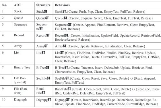
and graph (Wang, 2007). A summary of the ten typical ADTs is provided in Table 1 where the structures and behaviors of the ADTs are described. ADTs possess the following proper-ties: (i) An extension of type constructions by integrating both data structures and functional behaviors; (ii) A hybrid data object modeling technique that encapsulates both user defined data structures (types) and allowable operations on them; (iii) The interface and implementation of an ADT are separated. Detailed implementa-tion of the ADT is hidden to applicaimplementa-tions that invoke the ADT and its predefined operations.
There are a number of approaches to the specification of ADTs. Mathematically, the main approaches are of logical and algebraic, as well as their combinations. Although each of these approaches has its advantages, there are gaps when applying them to solve real-world problems. The logical approach is good at specifying high-level static behaviors of ADTs in forms of their preconditions and post-con-ditions of operations. For instance, a specifica-tion of queue as an ADT in predicate logic is shown in Figure 1 (Stubbs & Webre, 1985). However, the logic-based approach is not
suit-Copyright © 2010, IGI Global. Copying or distributing in print or electronic forms without written permission of IGI Global is prohibited.
Table 1. Summary of typical ADTs in software system modeling
No. ADT Structure Behaviors
1 Stack StackST StackST.{Create, Push, Pop, Clear, EmptyTest, FullTest, Release} 2 Queue QueueST QueueST.{Create, Enqueue, Serve, Clear, EmptTest, FullTest, Release} 3 Sequence
Sequen-ceST SequenceFullTest, Release}ST.{Create, Append, FindElement, Retrieve, Clear, EmptyTest, 4 Record RecordST RecordST.{Create, Initialization, UpdateField, UpdateRecord, RetrieveField,
RetrieveRecord, Release}
5 Array ArrayST ArrayST.{Create, Update, Retrieve, Initialization, Clear, Release} 6 List ListST ListST.{Create, FindNext, FindPrior, FindIth, FindKey, Retrieve, Update,
InsertAfter, InsertBefore, Delete, CurrentPos, FullTest, EmptyTest, GetSize, Clear, Release}
7 Binary Tree B-TreeST B-TreeST.{Create, Traverse, Insert, DeleteSub, Update, Retrieve, Find, Characteristics, EmptyTest, Clear, Release}
8 File
(Se-quential) SeqFileST SeqFileEmptyTest, FullTest}ST.{Create, Open, Reset, Save, Close, Delete} ∪ {Read, Append, 9 File
(Ran-dom) Rand-FileST RandFiletRec, UpdateRec, DeleteRec, EmptyTest, FullTest}ST.{Create, Open, Reset, Save, Close, Delete} ∪ {ReadRec, Inser-10 Diagraph DigrapgST DigrapgST.{Create, InsertNode, InsertEdge, DeleteNode, DeleteEdge,
Re-trieve, Update, FindNode, FindEdge, CurrentNode, CurrentEdge, Release}
able for behavioral refinement and the model-ing of dynamic behaviors of ADTs.
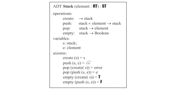
Another approach to ADT specification is the algebraic methods, which treat an ADT as an algebraic structure of sorts and operations on the sorts (McDermid, 1991). An algebraic model of an ADT, stack, is illustrated in Figure 2 (Louden, 1993). The advantage of algebraic models of ADTs is its abstraction and elegance. However, it is often too abstract for system implementers and users, especially for dealing with some non-trivial ADTs.
In order to enhance the algebraic methods and reduce their complexity, RTPA is introduced (Wang, 2007). The RTPA methodology provides an explicit and easy-to-use algebraic approach for ADT and system modeling. RTPA reveals two fundamental technologies for ADT system modeling and refinement known as the unified data model and the unified process model (Wang, 2007).
Definition 3. A Unified Data Model (UDM) is a generic architectural model of a software system as well as its hardware components, interfaces, and internal control structures, which can be rigorously modeled and refined in denotational mathematics as a tuple, i.e.:
UDM S e S , p e i n i i i i ( < | ( ) >) =1
R
NN ∀ ∈ (1)Definition 4. The Unified Process Model (UPM)
of a program ℘ is a composition of a finite set of k processes according to the time-, event-, and interrupt-based process dispatching rules, i.e.:
(2) This paper presents a formal algebraic modeling methodology for ADTs using a de-notational mathematics, RTPA, which allows both architectural and behavioral models of ADTs and complex data objects to be rigor-ously designed and implemented in a top-down approach. The methodology of a denotational mathematics based on RTPA is introduced to formally model and refine architectures, static behaviors, and dynamic behaviors of a set of ADTs. Stacks, queues, sequences, and
Figure 2. An algebraic model of the ADT stack (adapted from Louden, 1993)
ADT Stack(element : RT) : ST operations:
create: →stack
push: stack ×element →stack pop: stack →element empty: stack →Boolean variables: s: stack; e: element axioms: create (s) = s push (s, e) = es
pop (create( s)) = error pop (push (s, e)) = e empty (create( s)) = T empty (push (s, e)) = F
Copyright © 2010, IGI Global. Copying or distributing in print or electronic forms without written permission of IGI Global is prohibited.
records are chosen to comparatively elaborate the proposed RTPA-based ADT modeling methodologies. The architectural models of ATDs are created using the RTPA methodol-ogy known as UDMs. The static behaviors of ADTs are specified and refined by the RTPA methodology known as UPMs. The dynamic behaviors of ADTs are modeled by the RTPA methodology known as the event-driven process dispatching models.
THE FORMAL MODEL
OF ADT1 – STACKS
A stack is a typical data structure for modeling the Last-In-First-Out (LIFO) mechanism of an ADT with a set of elements in the same type. The conceptual model of stacks and its key control variables are introduced in this section. Based on it, formal models of the stack ADT in terms of its architectural and static/dynamic behavioral models are rigorously developed in RTPA.
The Conceptual Model of Stacks
The stack as a common data structure is de-scribed as shown in Figure 3. The protocol of stacks is LIFO, which implies that the I/O operations of stacks must be on its top or most recent elements as identified by the pointer of the current position. In the stack model, StackST, each ElementRT shares the same type where
RT represents the run-time type in RTPA. Two of the key control variables of the stack are SizeN denoting the maximum capacity of the stack and CurrentPosP denoting the current top position of the stack. The addresses of elements grow from the bottom up with the relative base address at 0H.
The top-level ADT model of the stack, StackST, encompassing its architecture, static behaviors, and dynamic behaviors, can be specified in RTPA as follows:
ADT§.StackST StackST.ArchitectureST || StackST.StaticBehaviorsPC || StackST.DynamicBehaviorsPC (3) According to the RTPA methodology for system modeling, specification, and refinement (Wang, 2007, 2008a), the following subsections will refine the top level framework of StackST into detailed architectural models (UDMs) and behavioral models (UPMs).
The Architectural Model of Stacks
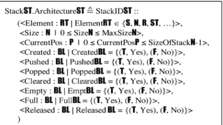
The architecture of StackST can be rigorously modeled using the UDM technology of RTPA, which is a predefined class of system hardware or internal control models that can be inher-ited or implemented by corresponding UDM objects as specific instances in the succeed-ing architectural refinement for the system. The UDM model of the stack ADT, StackST. ArchitectureST, as shown in Figure 4 provides a generic architectural model for any concrete stack in applications with three key fields, i.e., ElementRT, SizeN, and CurrentPosP, where the constraints of each field are given in the right-hand side of the vertical bar. Supplement to the key architectural attributes, there is a set of status fields in the stack, which models the current operational status of the stack in Boolean type such as CreatedBL, PushedBL, PoppedBL, ClearedBL, EmptyBL, FullBL, and ReleasedBL. It is noteworthy that the type of the data elements in an abstract stack is speci-fied in the run-time type RT, i.e., RT∈ {S, N, R, ST, …}, for design flexibility. However, the data elements in a concrete stack must be in the same type once it is chosen at run-time for a specific implementation of an instance of the generic abstract stack.
The Static Behavioral Model of Stacks
A static behavior is an encapsulated function of a given system that can be determined
before run-time (Wang, 2007). On the basis of the UDM model of StackST developed in the preceding subsection, the behaviors of the stack can be modeled as a set of UPMs operat-ing on the UDMs and related input variables. The high-level behavioral model of the stack ADT is modeled by StackST.StaticBehaviorsPC
as shown in Eq. 4. It can be further refined by a set of UPMs for each of the behavioral processes. The schemas of the UPMs in Eq. 4 model the input data objects (<I:: (…)>), output data objects (<O:: (…)>), and operated UDMs (<UDM:: (…)>) for each specific process of StackST. The UDMs play an important role in system architectural design as global and permanent I/O structures, which usually have a longer life-span than those of the process(es) that created and/or invoked them, particularly in a real-time system.
StackST.StaticBehaviorsPC
( CreateStackPC(<I:: StackIDS, SizeN, ElementRT>; <O:: StackIDST.CratedBL>; <UDM:: StackIDST>) | PushPC(<I:: StackIDS, ElementRT>; < O:: StackIDST. PushedBL>; <UDM:: StackIDST>)
| PopPC(<I:: StackIDS>; < O:: StackIDST.PoppedBL, ElementRT>; <UDM:: StackIDST>)
| ClearPC(<I:: StackIDS>; < O:: StackIDST.ClearedBL>; <UDM:: StackIDST>)
| EmptyTest (<I:: StackIDS>; < O:: StackIDST .Emp-tyBL>; <UDM:: StackIDST>)
| FullTest (<I:: StackIDS>; < O:: StackIDST.FullBL>; <UDM:: StackIDST>)
| ReleaseStackPC(<I:: StackIDS>; < O:: StackIDST. ReleasedBL>; <UDM:: StackIDST>)
) (4)
The following subsections describe how each of the seven behavioral processes of ADT StackST
as specified in Eq. 4 are modeled and refined using the denotational mathematical notations and methodologies of RTPA.
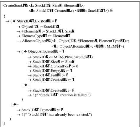
a) The Process of Stack Creation The stack creation process of StackST, Cre-ateStackPC, is formally modeled as shown in Figure 5, which establishes a new stack in system memory and links it to a specified logi-cal ID. The input arguments of the process are the given name of the stack as well as its size and the type of element. The output result and status are the creation of the stack as well as the settings of related initial values in the UDM of StackIDST.ArchitectureST. In order to create a physical stack and link it to the logical name of StackIDST, the process calls a system sup-port process, AllocateObjectPC, for dynamic memory manipulation for ADTs as illustrated in Figure 12. When the given stack has already existed or cannot be established due to memory
Copyright © 2010, IGI Global. Copying or distributing in print or electronic forms without written permission of IGI Global is prohibited.
availability, CreateStackPC results in a specific error message and sets StackIDST.CreatedBL = F. b) The Process of Stack Push
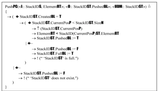
The push process of StackST, PushPC, is for-mally modeled as shown in Figure 6, which puts a given element onto the top of the stack. The input arguments of the process are the target stack ID and the given element. The output is the status of the push operation. PushPC writes the given element onto the top of the current stack contents, after checking that the stack is not full and the CurrentPosP has been updated. When the given stack has already been full or does not exist, PushPC generates a specific er-ror message and sets StackIDST.PushedBL = F.
c) The Process of Stack Pop
The pop process of StackST, PopPC, is formally modeled as shown in Figure 7, which elicits the top element of the stack. The input argument of the process is the target stack ID. Its outputs are the top element obtained and the status of the pop operation. When the target stack is not empty, PopPC does not only read the current top element of the stack, but also remove it from the stack. As a result, PopPC reduces the current pointer by one after the pop operation. When the given stack has already been empty or does not exist, PopPC generates a specific error message and sets StackIDST.PoppedBL = F.
d) The Process of Clear Stack
The clear process of StackST, ClearPC, is for-mally modeled as shown in Figure 8, which logically sets all elements of the stack as empty. The input argument of the process is the given stack ID. Its output is the status of the clear operation. ClearStackPC only logically sets the pointer StackIDST.CurrentPosP = 0 in order to denote the stack has been cleaned, rather than to remove all data elements of the stack. It is noteworthy that ClearStackPC is different from ReleaseStackPC, where the former logically declares the given stack as empty, while the latter physically removes the target stack as well as its contents from the memory. If the given stack does not exist, ClearStackPC generates a specific error message.
e) The Process of Stack Empty Test The empty test process of StackST,
EmptyTest-PC, is formally modeled as shown in Figure 9, which detects whether a given stack is empty. The input argument of the process is the target stack ID. Its output is the status of the stack as being empty or not. The status of an empty stack is characterized by StackIDST.CurrentPosP = 0. Therefore, EmptyTestPC verifies if the logical top pointer StackIDST.CurrentPosP points at the relative base address of the stack in order to determine whether the stack is empty or not.
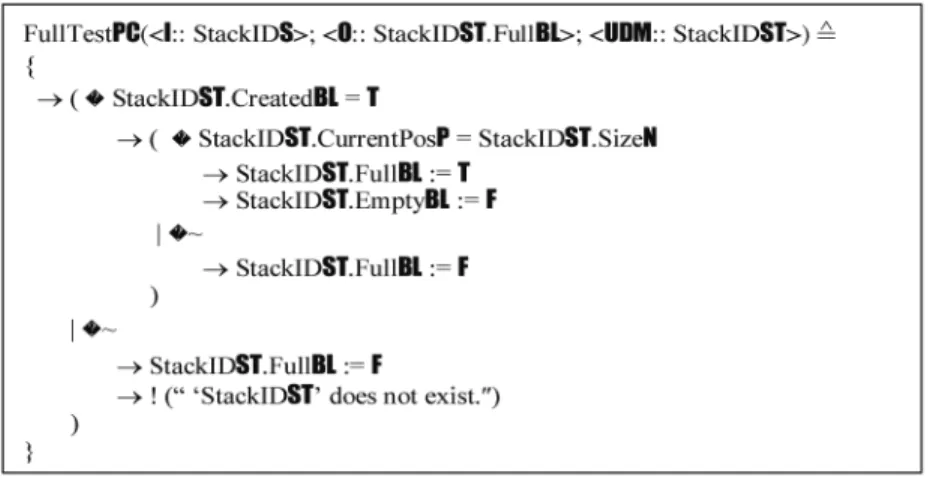
When the target stack does not exist, Emp-tyTestPC generates a specific error message. f) The Process of Stack Full Test The full test process of StackST, FullTestPC, is formally modeled as shown in Figure 10, which detects whether a given stack is full. The input argument of the process is the target stack ID. Its output is the status of the stack as being full or not. The status of a full stack is characterized by StackIDST.CurrentPosP = StackIDST.SizeN. Therefore, FullTestPC verifies if the logical top pointer StackIDST.CurrentPosP is equal to the physical size of the stack StackIDST.SizeN
in order to determine whether the stack is full or not. When the given stack does not exist, FullTestPC generates a specific error message.
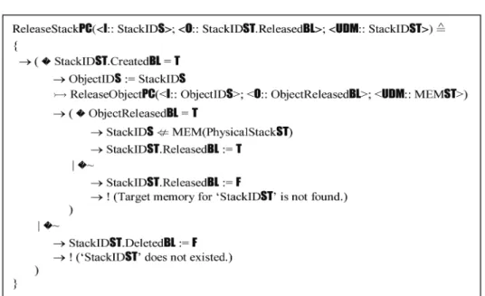
g) The Process of Stack Release The stack release process, ReleaseStackPC, is formally modeled as shown in Figure 11, which physically removes a given stack and related memory with the contents. The input argument of the process is the given stack ID. Its output is the status of the release operation. ReleaseStackPC disconnects the physical stack and its logical name. Then, the memory space of the physical stack is returned to the system by calling a system support process, ReleaseOb-jectPC, for dynamic memory manipulation for ADTs as illustrated in Figure 13. If the given stack does not exist logically or physically, Re-leaseStackPC produces a specific error message and sets StackIDST.ReleasedBL = F.
Copyright © 2010, IGI Global. Copying or distributing in print or electronic forms without written permission of IGI Global is prohibited.
h) Associate Processes of Dynamic Memory Manipulations for ADTs There are two support processes, AllocateOb-jectPC and ReleaseObjectPC, for dynamic memory allocation and the management of ADT creation and release manipulations. The
Allo-cateObjectPC process as shown in Fig. 12 finds out a suitable block of available memory for the required ObjectST, whose size is determined by: #ElementsN × Byte(ElementTypeRT)N bytes. AllocateObjectPC repetitively requests a unit of suitable bytes for each element of ObjectST. Then, it links the logical ID of the object to the
Figure 6. The UPM model of the stack push process
Figure 8. The UPM model of the stack clear process
Figure 9. The UPM model of the stack empty test process
Copyright © 2010, IGI Global. Copying or distributing in print or electronic forms without written permission of IGI Global is prohibited.
Figure 11. The UPM model of the release stack process
Figure 13. The UPM model of the release object process Figure 12. The UPM model of the allocate object process
Proof, IJSSCI Vol. 2(4) – EP V.1.0
2
Original Fig. 12
AllocateObjectPC(<I:: ObjectIDS, #ElementsN, ElementTypeRT >;
<O:: ObjectIDST.ExistedBL>, <UDM:: ObjectIDST, MemoryST>)
{ nN:= #ElementsN → n i =1
R
NN New (ObjectID(iN)ST: ElementTypeRT)
→(ObjectAllocatedBL=T →ObjectIDS⇐MEM(ObjectIDST)ST →ObjectIDST.ExistedBL:= T |~ →ObjectIDST.ExistedBL:= F ) } Original Fig. 18
ServePC(<I:: QueueIDS>; <O:: QueueIDST.ServedBL, ElementRT>; <UDM:: QueueIDST>)
{
→(QueueIDST.CreatedBL=T
→( QueueIDST.CurrentPosP> 0
→QueueID(1)ST.ElementRT⋗ElementRT
→
CurrentPos i =2
R
PN QueueID(iN))ST.ElementRT⋗QueueID(iN-1))ST.ElementRT → ↓(QueueIDST.CurrentPosP) →QueueIDST.ServedBL:= T |~ →QueueIDST.ServedBL:= F →QueueIDST.EmptyBL:= T →! (“ ‘QueueIDST’ is empty.″) ) |~ →QueueIDST.ServedBL:= F
→! (“ ‘QueueIDST’ does not exist.″) )
allocated memory block. If memory allocation is failed, AllocateObjectPC feeds back an error message ObjectIDST.ExistedBL = F.
The ReleaseObjectPC process is a support pro-cess as shown in Figure 13, which is invoked by an ADT release process such as ReleaseStackPC. The ReleaseObjectPC process identifies an as-sociate memory block of a given ObjectIDS
and disconnects the object from the memory. After the release operation, the object is set to be undefined, i.e., ObjectIDS:= ⊥. If memory release is failed, ReleaseObjectPC feeds back an error message ObjectIDST.ReleasedBL = F.
The Dynamic Behavior Model of Stacks
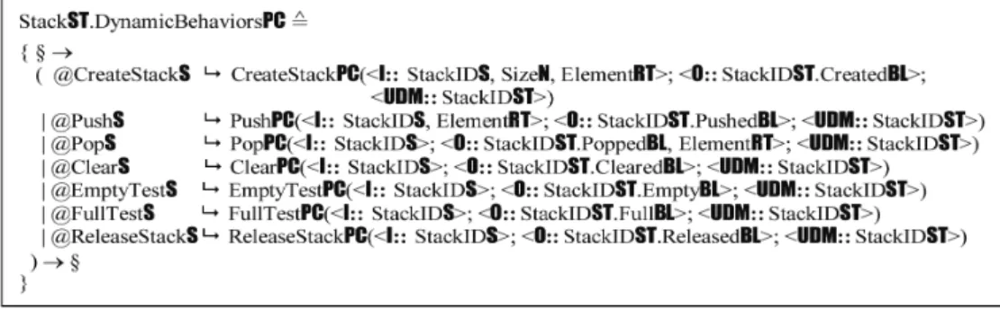
Dynamic behaviors of a system are run-time process deployment and dispatching mecha-nisms based on the static behaviors. Because system static behaviors are a set of component processes of the system, to put the static pro-cesses into an interacting system at run-time, the dynamic behaviors of the system in terms of process dispatching are yet to be specified. With the work products, StackST.StaticBehaviorsPC, developed in the preceding section as a set of static behavioral processes, this subsection describes the dynamic behaviors of StackST at run-time using the RTPA process dispatching methodology. StackST.DynamicBehaviorsPC
as shown in Figure 14 models the event-driven behaviors of StackST, which establishes the relations between system events and the stack behavioral processes. The event-driven dis-patching mechanisms also put StackST into the context of applications.
Figures 3 through 14 describe a typical ADT model, StackST, in a coherent design and using an unified formal notation. With the RTPA specification and refinement methodology, the mechanisms, architectures, and behaviors of StackST are rigorously and precisely modeled.
THE FORMAL MODEL
OF ADT2 – QUEUES
A queue is a typical data structure for modeling the First-In-First-Out (FIFO) mechanism of an
ADT with a set of elements in the same type. The conceptual model of queues and its key control variables are introduced in this section. Based on it, formal models of the queue ADT in terms of its architectural and static/dynamic behavioral models are rigorously developed in RTPA.
The Conceptual Model of Queues
The queue as a common data structure is de-scribed as shown in Figure 15. The protocol of queues is FIFO, which implies that the I/O operations of queues must be at both its tail and head, respectively. In the queue model, QueueST, each elementRT share the same type RT. Two of the key control variables of the queue are SizeOfQueueN denoting the maximum capacity of the queue and Current-PosP denoting the current tail position of the queue. The address of an element is growing from head to tail with the relative base address reserved at 0H. The head or the front element of the queue, Element1RT, is always located at address 1H based on the relative base address of the queue BaseN.
The top-level ADT model of queue, QueueST, encompassing its architecture, static behaviors, and dynamic behaviors, can be specified in RTPA as follows:
ADT§.QueueST QueueST.ArchitectureST
|| QueueST.StaticBehaviorsPC
|| QueueST.DynamicBehaviorsPC (5) According to the RTPA methodology for system modeling, specification, and refinement (Wang, 2007, 2008a), the following subsections will refine the top level framework of QueueST
into detailed architectural models (UDMs) and behavioral models (UPMs).
The Architectural Model of Queues
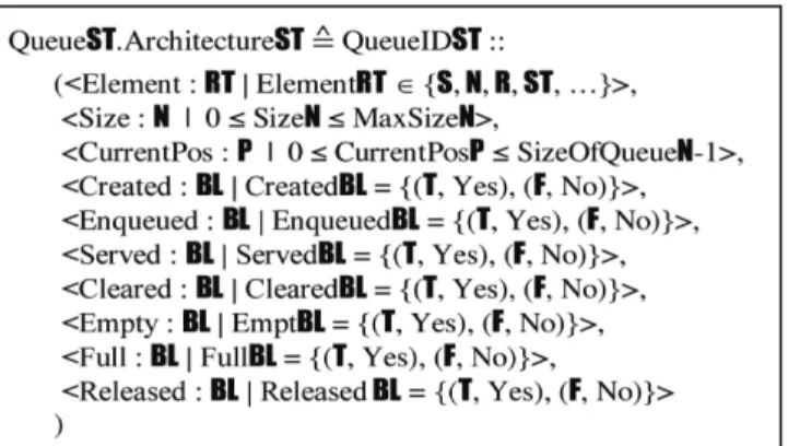
The architecture of QueueST can be rigorously modeled using the UDM technology of RTPA. The UDM model of the queue ADT, QueueST. ArchitectureST, as shown in Figure 16 provides
Copyright © 2010, IGI Global. Copying or distributing in print or electronic forms without written permission of IGI Global is prohibited.
a generic architectural model for any concrete queue in applications with three key fields, i.e., ElementRT, SizeN, and CurrentPosP, where the constraints of each field are given in the right-hand side of the vertical bar. Supplement to the key architectural attributes, there is a set of status fields in the queue, which models the cur-rent operational status of the queue in Boolean type such as CreatedBL, EnqueuedBL, ServedBL, ClearedBL, EmptyBL, FullBL, and ReleasedBL.
The Behavioral Model of Queues
On the basis of the UDM model of QueueST
developed in the preceding subsection, the be-haviors of the queue can be modeled as a set of UPMs operating on the UDMs and related input variables. The high level behavioral model of the queue ADT is modeled by QueueST .Stat-icBehaviorsPC as shown in Eq. 6. The schemas of the queue can be further refined by a set of UPMs for each of the behavioral processes.
QueueST.StaticBehaviorsPC
( CreateQueuePC(<I:: QueueIDS, SizeN, ElementRT>;
<O:: QueueIDST.CreatedBL>; <UDM:: QueueIDST>)
| EnqueuPC(<I:: QueueIDS, ElementRT>; < O:: QueueIDST.EnqueuedBL>;
<UDM:: QueueIDST>)
| ServePC(<I:: QueueIDS>; < O:: QueueIDST.ServedBL, ElementRT>; <UDM:: QueueIDST>)
| ClearPC(<I:: QueueIDS>; <
O:: QueueIDST.ClearedBL>; <UDM:: QueueIDST>)
| EmptyTest (<I:: QueueIDS>; < O:: QueueIDST.EmptyBL>; <UDM:: QueueIDST>)
| FullTest (<I:: QueueIDS>; < O:: QueueIDST.FullBL>; <UDM:: QueueIDST>)
| ReleaseQueuePC(<I:: QueueIDS>; < O:: QueueIDST.ReleasedBL>; <UDM:: QueueIDST>)
) (6)
Figure 14. The dynamic behavioral model of the stack ADT
A set of seven behavioral processes such as create, enqueue, serve, clear, empty test, full test, and release is designed in QueueST. StaticBehaviorsPC. The following subsections describe how the static behaviors of QueueST
as specified in Eq. 6 are modeled and refined using the denotational mathematical notations and methodologies of RTPA. Because of the similarity of the ADT manipulation processes between QueueST and StackST as described in Eq. 4, only two key processes, EnqueuePC and ServePC, of QueueST will be formally modeled in the following subsections.
a) The Process of Enqueue
The enqueue process of QueueST, EnqueuePC, is formally modeled as shown in Figure 17, which puts a given element at the tail of the queue. The input arguments of the process are the target queue ID and a given element. Its output is the status of the enqueue operation. EnqueuePC
checks if the given queue is not full and shifts CurrentPosP to the next position of the current tail, before the given element is appended into the queue. As a consequence, CurrentPosP of the queue is increased by one. When the given queue has already been full or does not exist, EnqueuePC generates a specific error message and sets QueueIDST.EnqueueBL = F.
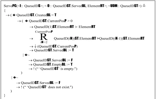
b) The Process of Serve Queue The serve process of QueueST, ServePC, is formally modeled as shown in Figure 18, which obtains the element in the front of the queue. The input argument of the process is the target queue. Its outputs are the front element of the queue and the status of the serve operation. The serve operation may be carried out when the given queue is not empty. Once the front element is elicited, ServePC has to update the queue by shifting all other elements that fol-low the currently removed front element by one place towards the front of the queue. As a consequence, CurrentPosP of the queue is decreased by one. When the given queue has already been empty or does not exist, ServePC
generates a specific error message and sets QueueIDST.ServedBL = F.
Contrasting the behavioral models of QueueST.BehaviorsPC in RTPA as developed in this section and that of predicate logic as shown in Figure 1, advances of the RTPA method and notations are well demonstrated. Among them, the most important merit is that an ADT model in RTPA can be seamlessly transformed into code in any programming language when the formal models are designed and refined systematically.
The Dynamic Behavior Model of Queues
On the basis of the work products, QueueST. StaticBehaviorsPC, developed in the preceding subsection as a set of static behavioral processes, this subsection describes the dynamic behav-iors of QueueST at run-time using the RTPA process dispatching methodology. QueueST. DynamicBehaviorsPC as shown in Figure 19 models the event-driven behaviors of QueueST, which establishes the relations between system events and the stack behavioral processes. The event-driven dispatching mechanisms also put QueueST into the context of applications.
Figures 15 through 19 describe a typical ADT model, QueueST, in a coherent design and using a unified formal notation. With the RTPA specification and refinement methodology, the mechanisms, architectures, and behaviors of QueueST are rigorously and precisely modeled.
THE FORMAL MODEL OF
ADT3 – SEQUENCES
A sequence is a typical data structure for modeling an ADT with a series of elements in the same type where their order information is important. The conceptual model of sequences and its key control variables are introduced in this section. Based on it, formal models of the sequence ADT in terms of its architectural and static/dynamic behavioral models are rigorously developed in RTPA.
Copyright © 2010, IGI Global. Copying or distributing in print or electronic forms without written permission of IGI Global is prohibited.
The Conceptual Model of Sequences
The sequence as a common data structure is described as shown in Figure 20. The protocol of sequence is FIFO, which implies that the I/O operations of sequence must be at its tail and head, respectively. In the sequence model, SequenceST, each ElementRT share the same type RT. Two of the key control variables of the sequence are SizeN denoting the maximum capacity of the sequence and CurrentPosP
denot-ing the current tail position of the sequence. The addresses of elements grow from the head to the tail with the relative base address reserved at 0H. The head or the front element of the sequence, Element1RT, is always located at address 1H based on the relative base address of the sequence BaseN.
The top-level ADT model of sequence, SequenceST, encompassing its architecture, static behaviors, and dynamic behaviors, can be modeled in RTPA as follows:
Figure16. The UDM model of the queue ADT
ADT§.SequenceST SequenceST. ArchitectureST
|| SequenceST.StaticBehaviorsPC
|| SequenceST.DynamicBehaviorsPC (7) According to the RTPA methodology for system modeling, specification, and refinement (Wang, 2007, 2008a), the following subsections will refine the top level framework of Sequen-ceST into detailed architectural models (UDMs) and behavioral models (UPMs).
The Architectural Model of Sequences
The architecture of SequenceST can be rig-orously modeled using the UDM technology of RTPA. The UDM model of the sequence ADT, SequenceST.ArchitectureST, as shown in Figure 21 provides a generic architectural model for any concrete sequence in applications with three key fields, i.e., ElementRT, SizeN, and CurrentPosP, where the constraints of each field are given in the right-hand side of the vertical bar. Supple-ment to the key architectural attributes, there is a set of status fields in the sequence, which models the current operational status of the sequence in Boolean type such as CreatedBL, AppendedBL, FirstFoundBL, LastFoundBL, RetrievedBL, ClearedBL, EmptyBL, FullBL, and ReleasedBL.
The Behavioral Model of Sequences
On the basis of the UDM model of Sequen-ceST developed in the preceding subsection, the behaviors of the sequence can be modeled as a set of UPMs operating on the UDMs and related input variables. The high level behav-ioral model of the sequence ADT is modeled by SequenceST.StaticBehaviorsPC as shown in Eq. 8. The schemas of the sequence can be further refined by a set of UPMs for each of the behavioral processes.
A set of eight behavioral processes such as create, append, find element, retrieve, clear,
empty test, full test, and release is designed in SequenceST.StaticBehaviorsPC. The following subsections describe how the static behaviors of SequenceST as specified in Eq. 8 are modeled and refined using the denotational mathematical notations and methodologies of RTPA. Because of the similarity of ADT manipulation processes between SequenceST and StackST as described in Eq. 4, only key processes, AppendPC, Fin-dElementPC, and RetrievePC, of SequenceST
will be formally modeled in the following subsections.
SequenceST.StaticBehaviorsPC
( CreateSequencePC(<I:: SequenceIDS, SizeN, ElementRT>;
<O:: SequenceIDST.CratedBL>; <UDM:: SequenceIDST>)
| AppendPC(<I:: SequenceIDS, Elemen-tRT>; < O:: SequenceIDST.AppendedBL>;
<UDM:: SequenceIDST>)
| FindElementPC(<I:: SequenceIDS, ElementRT>; < O:: SequenceIDST .Element-FoundBL,
ElementPositonP>; <UDM:: Sequen-ceIDST>)
| RetrievePC(<I:: SequenceIDS, iN>; <
O:: SequenceIDST.RetrievedBL, ElementRT>; <UDM:: SequenceIDST>)
| ClearPC(<I:: SequenceIDS>; < O:: SequenceIDST.ClearedBL>; <UDM:: Sequen-ceIDST>)
| EmptyTest (<I:: SequenceIDS>; < O:: SequenceIDST.EmptyBL>; <UDM:: Sequen-ceIDST>)
| FullTest (<I:: SequenceIDS>; < O:: SequenceIDST.FullBL>; <UDM:: Sequen-ceIDST>)
| ReleaseSequencePC(<I:: Sequen-ceIDS>; < O:: SequenceIDST.ReleasedBL>; <
:: SequenceIDST>)
) (8)
a) The Process of Sequence Append The append process of SequenceST, AppendPC, is formally modeled as shown in Figure 22,
88 International Journal of Software Science and Computational Intelligence, 2(4), 72-100, October-December 2010
Copyright © 2010, IGI Global. Copying or distributing in print or electronic forms without written permission of IGI Global is prohibited.
2 Original Fig. 12
AllocateObjectPC(<I:: ObjectIDS, #ElementsN, ElementTypeRT >;
<O:: ObjectIDST.ExistedBL>, <UDM:: ObjectIDST, MemoryST>)
{ nN:= #ElementsN → n i =1
R
NN New (ObjectID(iN)ST: ElementTypeRT) →(ObjectAllocatedBL=T →ObjectIDS⇐MEM(ObjectIDST)ST →ObjectIDST.ExistedBL:= T |~ →ObjectIDST.ExistedBL:= F ) } Original Fig. 18
ServePC(<I:: QueueIDS>; <O:: QueueIDST.ServedBL, ElementRT>; <UDM:: QueueIDST>) {
→(QueueIDST.CreatedBL=T
→( QueueIDST.CurrentPosP> 0
→QueueID(1)ST.ElementRT⋗ElementRT →
CurrentPos i =2
R
PN QueueID(iN))ST.ElementRT⋗QueueID(iN-1))ST.ElementRT → ↓(QueueIDST.CurrentPosP) →QueueIDST.ServedBL:= T |~ →QueueIDST.ServedBL:= F →QueueIDST.EmptyBL:= T →! (“ ‘QueueIDST’ is empty.″) ) |~ →QueueIDST.ServedBL:= F →! (“ ‘QueueIDST’ does not exist.″) )
}
Figure 18. The UPM model of the serve queue process
Figure 19. The dynamic behavioral model of the queue ADT
which puts an element at the current end of the sequence. The input arguments of the pro-cess are the target sequence ID and the given element. Its output is the status of the append operation. AppendPC writes the given element at the end of the sequence after checking that the sequence is not full and CurrentPosP is shifted to the address of the next element of the current tail. When the given sequence has already been full or does not exist, AppendPC
generates a specific error message and sets SequenceIDST.AppendedBL = F.
b) The Process of Find Element in a Sequence
The find element process of SequenceST, FindElementPC, is formally modeled as shown in Figure 23, which finds out the position of a given element in the sequence. The input argu-ments of the process are the target sequence ID and the given element. Its outputs are the posi-tion of the element in the sequence, if found, and the status of the search operation. FindEle-mentPC is a read-only operation that reports the position of the given element in a sequence, but
Figure 21. The UDM model of the sequence ADT
Copyright © 2010, IGI Global. Copying or distributing in print or electronic forms without written permission of IGI Global is prohibited.
does not change the structure and contents of the sequence. When the given sequence does not exist or is empty, FindElementPC generates a specific error message and sets SequenceIDST. ElementFoundBL = F.
c) The Process of Sequence Retrieve The retrieve process of SequenceST, RetrievePC, is formally modeled as shown in Figure 24, which reads the ith element in the sequence. The input arguments of the process are the target sequence ID and a given position in the sequence. Its outputs are the element at the given position, if any, and the status of the retrieve operation. RetrievePC is a read-only operation to find out the content at a certain position of the sequence, after conforming that the sequence is not empty. When the given sequence is empty or does not exist, RetrievePC
generates a specific error message and sets SequenceIDST.RetrievedBL = F.
The Dynamic Behavior Model of Sequences
On the basis of the work products, Se-quenceST.StaticBehaviorsPC, developed in the preceding subsection as a set of static behav-ioral processes, this subsection describes the dynamic behaviors of SequenceST at run-time using the RTPA process dispatching method-ology. SequenceST.DynamicBehaviorsPC as shown in Figure 25 models the event-driven behaviors of SequenceST, which establishes the relations between system events and the stack behavioral processes. The event-driven dispatching mechanisms also put SequenceST
into the context of applications.
Figures 20 through 25 describe a typical ADT model, SequenceST, in a coherent design and using a unified formal notation. With the RTPA specification and refinement methodol-ogy, the mechanisms, architectures, and behav-iors of SequenceST are rigorously and pre-cisely modeled.
THE FORMAL MODEL
OF ADT4 – RECORDS
A record is a typical data structure for model-ing an ADT with a set of fields configured in different types. The conceptual model of record and its key control variables are introduced in this section. Based on it, formal models of the record ADT in terms of its architectural and static/dynamic behavioral models are rigorously developed in RTPA. It is recognized that record is one of the most powerful and widely used ADTs and data structures, because it allows flexible field structures and data types. The mathematical model of a record is a tuple, which forms a fundamental architectural modeling means in ADT and software system modeling.
The Conceptual Model of Records
The record as a common data structure is described as shown in Figure 26. The proto-col of record is the direct accessibility to its fields, which implies that the I/O operations of records may be directly (randomly) conducted in any field of the record. In the record model, RecordST, the element in each field, Field(iN)
RTi is allowed in different types. Two of the key control variables of the record ADT are MaxFieldsN and #FieldsN. The former denotes the maximum allowable fields of the record; and the latter denotes the current position of the last field in the record. The addresses and the order of all fields are parallel and arbitrary. The constraints on each field of RecordST may be explicitly specified in the architectural model of the record.
The top-level ADT model of the record, RecordST, encompassing its architecture, static behaviors, and dynamic behaviors, can be modeled in RTPA as follows:
ADT§.RecordST RecordST .Architec-tureST
|| RecordST.StaticBehaviorsPC
|| RecordST.DynamicBehaviorsPC (9)
According to the RTPA methodology for system modeling, specification, and refinement (Wang, 2007, 2008a), the following subsections will refine the top level framework of RecordST
into detailed architectural models (UDMs) and behavioral models (UPMs).
The Architectural Model of Records
The architecture of RecordST can be rigor-ously modeled using the UDM technology of RTPA. The UDM model of the record ADT, RecordST.ArchitectureST, as shown in Figure 27 provides a generic architectural model for any concrete record in applications with two key parameters, i.e., #FieldsN and FiledType(iN)RT,
where the constraints on each field are given in the right-hand side of the vertical bar. Supple-ment to the key architectural attributes, there is a set of status fields in the record, which models the current operational status of the record in Boolean type such as CreatedBL, Initial-izedBL, FieldRetrievedBL, RecordRetrievedBL, FieldUpdatedBL, RecordUpdatedBL, ClearedBL, EmptyBL, FullBL, and ReleasedBL.
The Behavioral Model of Records
On the basis of the UDM model of RecordST
developed in the preceding subsection, the be-haviors of the record can be modeled as a set of UPMs operating on the UDMs and related input variables. The high level behavioral model of the record ADT is modeled by RecordST. StaticBehaviorsPC as shown in Eq. 10. The schemas of the record can be further refined by a set of UPMs for each of the behavioral processes. RecordST.StaticBehaviorsPC { CreateRecordPC(<I:: RecordIDS, #FieldsN, i =0 Fields
R
N N # -1 Field(iN)RT>;<O:: RecordIDST.CreatedBL>; <UDM:: RecordST>)
Copyright © 2010, IGI Global. Copying or distributing in print or electronic forms without written permission of IGI Global is prohibited.
Figure 24. The UPM model of the sequence retrieve process
Figure 25. The dynamic behavioral model of the sequence ADT
3
Original Fig. 27
RecordST.ArchitectureSTRecordIDST:: (<#Fields : N | 1≤#FieldsN≤ MaxFieldsN>, # Fields 1 i =0
R
N N − <FieldType(iN) : RT| FieldType(iN)RT∈{S,N,R,ST, …}> <Created : BL| CreatedBL= {(T, Yes), (F, No)}>,<Initialized : BL| InitializedBL= {(T, Yes), (F, No)}>,
<FieldRetrieved :BL| FieldRetrievedBL= {(T, Yes), (F, No)}>, <RecordRetrieved :BL| RecordRetrievedBL= {(T, Yes), (F, No)}>, <FieldUpdated : BL| FieldUpdatedBL= {(T, Yes), (F, No)}>, <RecordUpdated : BL| RecordUpdatedBL= {(T, Yes), (F, No)}>, <Released : BL| ReleasedBL= {(T, Yes), (F, No)}>
)
Original Fig. 30
RetrieveRecordPC(<I:: RecordIDS>; <O:: RecordIDST.RecordRetrievedBL,
# Fields i =0
R
NN
FieldID(iN)RT>; <UDM:: RecordST>)
{
→( RecordIDST.CreatedBL=T∧RecordIDST.#FieldsN≠0 →( #FieldsN= RecordIDST.#FieldN
→ # Fields 1 i =0
R
N N −RecordIDST.Field(iN)RT⋗FieldID(iN)RT →RecordIDST.RecordRetrievedBL:= T |~
→RecordIDST.RecordRetrievedBL:= F
→! (“Input field number does not match ‘RecordIDST’.″) )
|~
→RecordIDST.RecordRetrievedBL:= F →! (“ ‘RecordIDST’ does not exist or is empty.″) )
}
Original Fig. 32
Figure 27. The UDM model of the record ADT
Figure 28. The UPM model of the record initialization process
Copyright © 2010, IGI Global. Copying or distributing in print or electronic forms without written permission of IGI Global is prohibited.
Figure 30. The UPM model of the record retrieve process
| InitializeRecordPC(<I:: RecordIDS, InitialValueRT>; <O:: RecordIDST .Initial-izedBL>; <UDM:: RecordST>)
| RetrieveFieldPC(<I:: RecordIDS, iN>; <O:: RecordIDST.FieldRetrievedBL, Field(iN)
RT>; <UDM:: RecordST>) | RetrieveRecordPC(<I:: RecordIDS>; <O:: RecordIDST.RecordRetrievedBL, i =0 Fields
R
N N # -1Field(iN)RT>; <UDM:: Re-cordST>)
| UpdateFieldPC(<I:: RecordIDS, Field(iN)RT>; <O:: RecordIDST .FieldUpdat-edBL>; <UDM:: RecordST>) | UpdateRecordPC(<I:: RecordIDS, #FieldsN, i =0 Fields
R
N N # -1 Field(iN)RT>; <O:: RecordIDST.RecordUpdatedBL>; <UDM:: RecordST>) | ReleaseRecordPC(<I:: RecordIDS>; <O:: RecordIDST.ReleasedBL>; <UDM:: RecordST>)} (10)
A set of seven behavioral processes such as
create, initialize record, retrieve field, retrieve record, update field, update record, and release
is designed in RecordST.StaticBehaviorsPC. The following subsections describe how the static behaviors of RecordST as specified in Eq. 10 are modeled and refined using the denotational mathematical notations and methodologies of RTPA. Because of the similarity of ADT manipulation processes between RecordST
and StackST as described in Eq. 4, only key processes, InitializeRecordPC, RetrieveFieldPC, RetrieveRecordPC, UpdateFieldPC, and Up-dateRecordPC, of RecordST will be formally modeled in the following subsections. a) The Process of Record Initialization
The record initializing process of RecordST, InitializeRecordPC, is formally modeled as shown in Figure 28, which sets each element of the record with the same given initial value. The input arguments of the process are the
target record ID and the given initial value. Its output is the status of the initialization opera-tion. InitializeRecordPC puts the initial value into each element of the record, after checking that the record exists and is not empty. When the given record is empty or does not exist, InitializeRecordPC generates a specific error message and sets RecordIDST.InitializedBL = F.
b) The Process of Record Field Retrieve
The record field retrieve process of RecordST, RetrieveFieldPC, is formally modeled as shown in Figure 29, which reads the contents of a given field of the record. The input arguments of the process are the target record ID and the number of the expected field. Its outputs are the contents of the given field in the record and the status of the retrieve operation. RetrieveFieldPC
is a read-only operation to report the contents of a specific field in the record. Before the retrieve is conducted, the given number of the field must be validated and the record must not be empty. When the given record is empty or does not exist, RetrieveFieldPC generates a specific error message and sets RecordIDST. FieldretrievedBL = F.
c) The Process of Record Retrieve The record retrieve process of RecordST, Re-trieveRecordPC, is formally modeled as shown in Figure 30, which reads the contents of all fields from the given record. The input argu-ment of the process is the target record ID. Its outputs are the contents of each fields of the record and the status of the retrieve operation. RetrieveRecordPC is a read-only operation to repetitively report the contents of all fields in the record. When the given record is empty or does not exist, RetrieveRecordPC generates a specific error message and sets RecordIDST. RecordRetrievedBL = F.
d) The Process of Update Record Field
The update record field process of RecordST, UpdateFieldPC, is formally modeled as shown in
Copyright © 2010, IGI Global. Copying or distributing in print or electronic forms without written permission of IGI Global is prohibited.
Figure 31, which writes a given value onto the specific field of the record. The input arguments of the process are the target record ID and the data for the given field. Its output is the status of the field update operation. UpdateFieldPC is an inverse operation of RetrieveFieldPC. Before the operation is carried out, the number of the filed must be validated and the record must be nonempty. When the given record is empty or does not exist, UpdateFieldPC generates a specific error message and sets StackIDST. FieldUpdatedBL = F; so also when the field index is out of scope.
e) The Process of Record Update The update record process of RecordST, Up-dateRecordPC, is formally modeled as shown in Figure 32, which writes a set of values onto each field of the record. The input arguments of the process are the target record ID, number of fields, and the data for each given field. Its output is the status of the record update opera-tion. UpdateRecordPC is an inverse operation of RetrieveRecordPC. Before the operation is carried out, the number of the filed must match with that of the record. When the given record is empty or does not exist, UpdateRecordPC
generates a specific error message and sets StackIDST.RecordUpdatedBL = F; so also when the total number of fields does not match that of the record.
The Dynamic Behavior Model of Record
On the basis of the work products, RecordST. StaticBehaviorsPC, developed in the preceding subsection as a set of static behavioral processes, this subsection describes the dynamic behaviors of RecordRecordST at run-time using the RTPA process dispatching methodology. RecordST. DynamicBehaviorsPC as shown in Figure 33 models the event-driven behaviors of RecordST, which establishes the relations between system events and the stack behavioral processes. The event-driven dispatching mechanisms also put RecordST into the context of applications.
Figures 26 through 33 describe a typical ADT model, Record ST, in a coherent design and using a unified formal notation. With the RTPA specification and refinement methodology, the mechanisms, architectures, and behaviors of RecordST are rigorously and precisely modeled.
The practical formal engineering methodol-ogy of RTPA for system modeling and specifi-cation provides a coherent notation system and systematic approach for large-scale software and hybrid system design and implementation. A series of formal design models of real-world and real-time applications in RTPA have been developed using RTPA notations and meth-odologies (Wang, 2002, 2007, 2008a, 2008b, 2009b; Wang & Huang, 2008) in the formal design engineering approach, such as the Tele-phone Switching System (TSS) (Wang, 2009b), the Lift Dispatching System (LDS) (Wang et al., 2009), the Automated Teller Machine (ATM) (Wang et al., 2010b), the Real-Time Operating System (RTOS+) (Wang et al., 2010c, 2010d), and the Air Traffic Control System (ATCS, to be reported). Further studies have demonstrated that RTPA is not only useful as a generic notation and methodology for software engineering, but also good at modeling human cognitive processes in cognitive informatics and computational intelligence as reported in (Wang, 2008d, 2009a; Wang & Ruhe, 2007; Wang & Chiew, 2010).
CONCLUSION
Abstract Data Types (ADTs) have been recog-nized as an important set of rigorously modelled complex data structures with pre-specified behaviors. This paper has introduced the formal RTPA modeling methodology for ADT architec-tures and behavioral specification and refine-ment in a top-down approach. The architectures, static behaviors, and dynamic behaviors of a set of typical ADTs such as stack, queue, sequence, and record, have been comparatively studied. Two generic methodologies of RTPA known as the Unified Data Models (UDMs) for system architectural modeling and the Unified Process
Copyright © 2010, IGI Global. Copying or distributing in print or electronic forms without written permission of IGI Global is prohibited.
Figure 33. The dynamic behavioral model of the record ADT
Figure 32. The UPM model of the record update process
Proof, IJSSCI Vol. 2(4) – EP V.1.0
UpdateRecordPC(<I:: RecordIDS,#FieldsN,
# Fields 1 i =0
R
N N − FieldID(iN)RT>; <O:: RecordIDST.RecordUpdatedBL>; <UDM:: RecordST>) {→( RecordIDST.CreatedBL=T∧RecordIDST.#FieldsN≠0 →( #FieldsN= RecordIDST.#FieldN
→ # Fields 1 i =0
R
N N −RecordIDST.Field(iN)RT:= Field(iN)RT
→RecordIDST.RecordUpdatedBL:= T |~
→RecordIDST. RecordUpdatedBL:= F
→! (“Input field number does not match ‘RecordIDST’.″) )
|~
→RecordIDST. RecordUpdatedBL:= F
→! (“ ‘RecordIDST’ does not exist or is empty.″) )
}
Original Fig. 33
RecordST.DynamicBehaviorsPC
{ §→
( @CreateRecordS CreateRecordPC(<I:: RecordIDS,#FieldsN,
# Fields 1 i =0
R
N N − Field(iN)RT>; <O:: RecordIDST.CreatedBL>; <UDM:: RecordST>)| @InitialRecordS InitializeRecordPC(<I:: RecordIDS, InitialValueRT>; <O:: RecordIDST.InitializedBL>; <UDM:: RecordST>)
| @RetrieveFieldS RetrieveFieldPC(<I:: RecordIDS, iN>; <O:: RecordIDST.FieldRetrievedBL, Field(iN)RT>; <UDM:: RecordST>)
| @RetrieveRecordS RetrieveRecordPC(<I:: RecordIDS>; <O:: RecordIDST.RecordRetrievedBL, # Fields 1 i =0
R
N N −Field(iN)RT>; <UDM:: RecordST>)
| @UpdateFieldS UpdateFieldPC(<I:: RecordIDS, Field(iN)RT>; <O:: RecordIDST.FieldUpdatedBL>; <UDM:: RecordST>)
| @UpdateRecordS UpdateRecordPC(<I:: RecordIDS,#FieldsN,
# Fields 1 i =0
R
N N − Field(iN)RT>;<O:: RecordIDST.RecordUpdatedBL>; <UDM:: RecordST>)
| @ReleaseQueueS ReleaseRecordPC(<I:: RecordIDS>; <O:: RecordIDST.ReleasedBL>; <UDM:: RecordST>) ) →§
}
Proof, IJSSCI Vol. 2(4) – EP V.1.0
4 UpdateRecordPC(<I:: RecordIDS,#FieldsN,
# Fields 1 i =0
R
N N − FieldID(iN)RT>; <O:: RecordIDST.RecordUpdatedBL>; <UDM:: RecordST>) {→(RecordIDST.CreatedBL=T∧RecordIDST.#FieldsN≠0 →( #FieldsN= RecordIDST.#FieldN
→ # Fields 1 i =0
R
N N −RecordIDST.Field(iN)RT:= Field(iN)RT
→RecordIDST.RecordUpdatedBL:= T |~
→RecordIDST. RecordUpdatedBL:= F
→! (“Input field number does not match ‘RecordIDST’.″) )
|~
→RecordIDST. RecordUpdatedBL:= F
→! (“ ‘RecordIDST’ does not exist or is empty.″) )
}
Original Fig. 33
RecordST.DynamicBehaviorsPC { §→
( @CreateRecordS CreateRecordPC(<I:: RecordIDS,#FieldsN,
# Fields 1 i =0
R
N N − Field(iN)RT>; <O:: RecordIDST.CreatedBL>; <UDM:: RecordST>)| @InitialRecordS InitializeRecordPC(<I:: RecordIDS, InitialValueRT>; <O:: RecordIDST.InitializedBL>; <UDM:: RecordST>)
| @RetrieveFieldS RetrieveFieldPC(<I:: RecordIDS, iN>; <O:: RecordIDST.FieldRetrievedBL, Field(iN)RT>; <UDM:: RecordST>)
| @RetrieveRecordS RetrieveRecordPC(<I:: RecordIDS>; <O:: RecordIDST.RecordRetrievedBL, # Fields 1 i =0
R
N N −Field(iN)RT>; <UDM:: RecordST>)
| @UpdateFieldS UpdateFieldPC(<I:: RecordIDS, Field(iN)RT>; <O:: RecordIDST.FieldUpdatedBL>; <UDM:: RecordST>)
| @UpdateRecordS UpdateRecordPC(<I:: RecordIDS,#FieldsN,
# Fields 1 i =0
R
N N − Field(iN)RT>; <O:: RecordIDST.RecordUpdatedBL>; <UDM:: RecordST>)| @ReleaseQueueS ReleaseRecordPC(<I:: RecordIDS>; <O:: RecordIDST.ReleasedBL>; <UDM:: RecordST>) ) →§
Copyright © 2010, IGI Global. Copying or distributing in print or electronic forms without written permission of IGI Global is prohibited.
Models (UPMs) for behavioral modeling have been elaborated. On the basis of the formal and rigorous models of the ADT system, code can be automatically generated or be manually transferred from the formal models.
The RTPA models of more complex ADTs such as universal arrays, lists, binary trees, files, and digraphs will be reported in related future work in the Series of Formal Software Design Models, Patterns, and Frameworks in IJSSCI. This work have been applied in a number of real-time and nonreal-time system designs and modeling such as a Real-Time Operating Sys-tem (RTOS+), an Air Traffic Control SysSys-tem (ATCS), as well as the developments of the ADT library of an RTPA support tool and the anonymous automatic code generator (RTPA-CG) (Wang et al., 2010a; Ngolah & Wang, 2009) based on RTPA.
ACKNOWLEDGMENT
The authors would like to acknowledge both the Natural Science and Engineering Council of Canada (NSERC) and the International In-stitute for Software Technology at the United Nations University (IIST/UNU) for their partial support to this work. We would like to thank the reviewers for their valuable comments and suggestions.
REFERENCES
Broy, M., Pair, C., & Wirsing, M. (1984). A Systematic Study of Models of Abstract Data Types. Theoretical Computer Science, 33, 139–1274. doi:10.1016/0304-3975(84)90086-0
Cardelli, L., & Wegner, P. (1985). On Understand-ing Types, Data Abstraction and Polymorphism. ACM Computing Surveys, 17(4), 471–522. doi:10.1145/6041.6042
Guttag, J. V. (1977). Abstract Data Types and the De-velopment of Data Structures. Communications of the ACM, 20(6), 396–404. doi:10.1145/359605.359618 Lipschutz, S., & Lipson, M. (1997). Schaum’s Outline of Theories and Problems of Discrete Mathematics (2nd ed.). New York: McGraw-Hill Inc.
Louden, K. C. (1993). Programming Languages: Principles and Practice. Boston: PWS-Kent Pub-lishing Co.
McDermid, J. (Ed.). (1991). Software Engineer’s Reference Book. Oxford, UK: Butterworth Heine-mann Ltd.
Mitchell, J. C. (1990). Type systems for programming languages . In van Leeuwen, J. (Ed.), Handbook of Theoretical Computer Science (pp. 365–458). Am-sterdam, The Netherlands: North Holland. Ngolah, C. F., & Wang, Y. (2009). Tool Support for Software Development based on Formal Specifica-tions in RTPA. International Journal of Software Engineering and Its Applications, 3(3), 71–88. Russel, B. (1903). The Principles of Mathematics. London: George Allen & Unwin.
Stubbs, D. F., & Webre, N. W. (1985). Data Structures with Abstract Data Types and Pascal. Monterey, CA: Brooks/Cole Publishing Co.
Wang, Y. (2002). The Real-Time Process Al-gebra (RTPA). Annals of Software Engineer-ing: An International Journal, 14, 235–274. doi:10.1023/A:1020561826073
Wang, Y. (2007). Software Engineering Founda-tions: A Software Science Perspective. Boca Raton, FL: CRC.
Wang, Y. (2008a). RTPA: A Denotational Mathemat-ics for Manipulating Intelligent and Computational Behaviors. International Journal of Cognitive In-formatics and Natural Intelligence, 2(2), 44–62. Wang, Y. (2008b). Mathematical Laws of Software. Transactions of Computational Science, 2, 46–83. doi:10.1007/978-3-540-87563-5_4
Wang, Y. (2008c). Deductive Semantics of RTPA. International Journal of Cognitive Informatics and Natural Intelligence, 2(2), 95–121.
Wang, Y. (2008d). On Contemporary Denota-tional Mathematics for ComputaDenota-tional Intelligence. Transactions of Computational Science, 2, 6–29. doi:10.1007/978-3-540-87563-5_2
Wang, Y. (2009a). Paradigms of Denotational Mathematics for Cognitive Informatics and Cogni-tive Computing. Fundamenta Informatic., 90(3), 282–303.
Wang, Y. (2009b). The Formal Design Model of a Telephone Switching System (TSS). International Journal of Software Science and Computational Intelligence, 1(3), 92–116.
Wang, Y., & Chiew, V. (2010). On the Cognitive Process of Human Problem Solving. Cognitive Systems Research: An International Journal, 11(1), 81–92. doi:10.1016/j.cogsys.2008.08.003
Wang, Y., & Huang, J. (2008). Formal Modeling and Specification of Design Patterns using RTPA. International Journal of Cognitive Informatics and Natural Intelligence, 2(1), 100–111.
Wang, Y., Ngolah, C. F., Ahmadi, H., Sheu, P. C. Y., & Ying, S. (2009). The Formal Design Model of a Lift Dispatching System (LDS). International Journal of Software Science and Computational Intelligence, 1(4), 98–122.
Wang, Y., Ngolah, C. F., Zeng, G., Sheu, P. C. Y., Choy, C. P., & Tian, Y. (2010c). The Formal Design Models of a Real-Time Operating System (RTOS+): Conceptual and Architectural Frameworks. Interna-tional Journal of Software Science and Computa-tional Intelligence, 2(2), 105–122.
Wang, Y., Ngolah, C. F., Zeng, G., Sheu, P. C. Y., Choy, C. P., & Tian, Y. (2010d). The Formal Design Models of a Real-Time Operating System (RTOS+): Static and Dynamic Behavior Models. International Journal of Software Science and Computational Intelligence, 2(3), 79–105.
Wang, Y., & Ruhe, G. (2007). The Cognitive Pro-cess of Decision Making. International Journal of Cognitive Informatics and Natural Intelligence, 1(2), 73–85.
Wang, Y., Tan, X., & Ngolah, C. F. (2010a). Design and Implementation of an Autonomic Code Generator based on RTPA (RTPA-CG). International Journal of Software Science and Computational Intelligence, 2(2), 44–67.
Wang, Y., Zhang, Y., Sheu, P. C. Y., Li, X., & Guo, H. (2010b). The Formal Design Models of an Auto-matic Teller Machine (ATM). International Journal of Software Science and Computational Intelligence, 2(1), 102–131.
Yingxu Wang is professor of cognitive informatics and software engineering, President of Inter-national Institute of Cognitive Informatics and Cognitive Computing (IICICC), and Director of Theoretical and Empirical Software Engineering Research Center (TESERC) at the University of Calgary. He is a Fellow of WIF, a P.Eng of Canada, a Senior Member of IEEE and ACM, and a member of ISO/IEC JTC1 and the Canadian Advisory Committee (CAC) for ISO. He received a PhD in Software Engineering from The Nottingham Trent University, UK, in 1997, and a BSc in Electrical Engineering from Shanghai Tiedao University in 1983. He has industrial experience since 1972 and has been a full professor since 1994. He was a visiting professor in the Comput-ing Laboratory at Oxford University in 1995, Dept. of Computer Science at Stanford University in 2008, and the Berkeley Initiative in Soft Computing (BISC) Lab at University of California, Berkeley in 2008, respectively. He is the founder and steering committee chair of the annual IEEE International Conference on Cognitive Informatics (ICCI). He is founding Editor-in-Chief of International Journal of Cognitive Informatics and Natural Intelligence (IJCINI), founding Editor-in-Chief of International Journal of Software Science and Computational Intelligence (IJSSCI), Associate Editor of IEEE Transactions on System, Man, and Cybernetics (Part A), As-sociate Editor of ASP Journal on Advanced Mathematics and Applications, and Editor-in-Chief of CRC Book Series in Software Engineering. He is the initiator of a number of cutting-edge
Copyright © 2010, IGI Global. Copying or distributing in print or electronic forms without written permission of IGI Global is prohibited.
research fields such as cognitive informatics, denotational mathematics (such as concept algebra, system algebra, real-time process algebra (RTPA), granular algebra, visual semantic algebra, and inference algebra), abstract intelligence, theoretical software engineering, and built-in tests. He has published over 110 peer reviewed journal papers, 200+ peer reviewed full confer-ence papers, and 12 books in cognitive informatics, software engineering, and computational intelligence. He is the recipient of dozens of leadership, research achievement, best paper, and teaching awards in the last 30 years.
Xinming Tan is a professor in the School of Computer Science and Technology at Wuhan University of Technology, China. He is the head of the Department of Computer Science. He received a BSc and an MSc in Computer Science at Wuhan University of Technology, and a PhD in Software Engineering at University of Calgary, Canada in 2007. His major research interests are in formal methods, real-time systems, and cognitive informatics.
Cyprian F. Ngolah received a PhD in Software Engineering from the University of Calgary, Canada in 2006, an MSc in Control Engineering from the University of Bradford, England in 1989, and a BSc in Mathematics and Computer Science from the University of Essex, England in 1988. He taught several computer science and software engineering courses at both the graduate and undergraduate levels for thirteen years at University of Buea, Cameroon. He is currently a senior software engineer in the Research and Development Department of Sentinel Trending & Diagnostics Ltd, Calgary, carrying out research on the development of a neural network for machine condition monitoring and predictive maintenance using vibration analysis. His main research interests are in real-time process algebra and its applications, tool support for formal specification languages, real-time operating systems, formal methods in software engineering and real-time software systems, and artificial neural networks.
Phillip C-Y. Sheu is currently a professor of Computer Engineering, Information and Computer Science, and Biomedical Engineering at the University of California, Irvine. He received his Ph.D. and M.S. degrees from the University of California at Berkeley in Electrical Engineering and Computer Science in 1986 and 1982, respectively, and his B.S. degree from National Tai-wan University in Electrical Engineering in 1978. Between 1982 and 1986, he also worked as a computer scientist at Systems Control Technology, Inc., Palo Alto, CA., where he designed and implemented aircraft expert control systems, and he worked as a product planning engineer at Advanced Micro Devices Inc., Sunnyvale, CA, where he designed and integrated CAD systems. From 1986 to 1988, he was an assistant professor at School of Electrical Engineering, Purdue University. From 1989 to 1993, he was an associate professor of Electrical and Computer En-gineering at Rutgers University. He has published two books: (1) Intelligent Robotic Planning Systems and (2) Software Engineering and Environment - An Object-Oriented Perspective,
and more than 100 papers in object-relational data and knowledge engineering and their ap-plications, and biomedical computations. He is currently active in research related to complex biological systems, knowledge-based medicine, semantic software engineering, proactive web technologies, and large real-time knowledge systems for defense and homeland security. His current research projects are sponsored by the National Science Foundation, National Institute of Health, and Department of Defense. Dr. Sheu is a Fellow of IEEE.