A Central Positron Source to Perform the
Timing Alignment of Detectors in a PET
Scanner
Christopher J. Thompson
Member IEEE
, Marie-Laure Camborde
Member IEEE
,
and Michael E. Casey
Senior Member IEEE
1
Abstract - Accurate timing alignment and stability is important to maximize the true counts and minimize the random counts in positron emission tomography . It importance increases in time-of-flight scanners. We propose using a central positron emitting source enclosed in a detector which detects the excess energy of the positron before it annihilates as a timing reference. All crystals can be time-aligned with respect to this central source. We evaluated 10 :Ci 22Na and 68Ge sources embedded in cylinders of plastic scintillator coupled to a fast PMT. Light flashes produced after the parent isotope emits positrons are detected, and the anode signals from the PMT are the reference time for each positron decay. The time delay before the gamma ray is detected by the scanner’s conventional gamma ray detectors is the time offset to be applied to that crystal. Since all detectors are almost the same distance from the central source, time-of-flight errors are minimized. Preliminary results show a mean signal amplitude of >0.5V from 22Na at 1000V PMT bias, a timing FWHM of 850 psec with respect to a small LSO crystal. This suggests it could be useful to align both conventional and time-of-flight PET scanners.
I. INTRODUCTION
An essential calibration procedure for a positron emission tomography (PET) scanner is the compensation for the apparent time at which a gamma ray is detected by each crystal, so that when a true coincidence is detected, it will be correctly identified. Timing alignment is normally done using an orbiting source, and an iterative procedure is then used to assign a offset to each detector. This is subject to time-of-flight errors, and lacks a precise time reference.
Aligning the detectors in a PET scanner so that they can detect coincident gamma rays with a narrow coincidence window is important in order to reduce random counts, and to provide stability. In spite of the availability of much faster scintillators [lutetium oxy-ortho-silicate (LSO): 40 nsec, gadolinium silicate (GSO): 70 nsec], compared with bismuth germanate (BGO): 300 nsec), most scanners still use a comparatively long coincidence resolving time. Recent experience with a Concorde MicroPET suggests that a 10 nsec. timing window is required for stable operation: the same used in our CTI HR+ scanner with BGO crystals[1] even though the intrinsic timing resolution is much better. There is presently renewed interest in the incorporation of time-of-flight information into PET reconstruction in order to improve PET image quality[2]. This would require more accurate time alignment than is presently needed. The time alignment of most scanners is performed with the orbiting source used for transmission scans. This is subject to time-of-flight (TOF) errors of ± 2 nsec. unless its position is known, since it typically orbits with a diameter of about 60 cm. Since there is no timing reference, an iterative procedure is used to assign a time offset to each detector. Recent studies on GE Advance PET scanner[3] show the benefits of a separate time offset being assigned to each crystal in a block detector, rather than the block as a whole. This makes the alignment procedure much longer, since number of counts required to establish an accurate time offset depends on the counts obtained from each detector and its timing resolution. Recent PET/CT scanners use the CT (X-ray computed tomography) scan for attenuation correction and so no longer require an orbiting source so a simple alternative method for time alignment would be desirable.
We have developed a very different concept for performing time alignment. We are evaluating a central timing alignment probe which can detect the positrons emitted during the decay of the isotope before they combine with an electron and annihilate. This serves as areference time to which all detectors in the scanner can be aligned. The source is placed in the centre of the scanner (to minimize time-of-flight effects). Many scanners can acquire data in “singles” mode and retain the time stamps which identify the time each gamma ray is detected. The difference between the detection of positron decay by the central source and the
1
Manuscript received October 20, 2004. This work was supported by grants from and National Science and Engineering Council of Canada (OGP-0036672) to Dr. Thompson.
C J Thompson is with the Montreal Neurological Institute, 3801 University St. Montreal, QC, Canada H3A 2B4.
Phone +1 (514) 398 8505 e-mail: [email protected] M-L Camborde is with the UBC Triumf PET Group, Brain Research Centre, 2211 Wesbrook Mall, Vancouver, BC V6T 2B5, Phone +1 (604) 822 7149 e-mail: [email protected]
M. E. Casey is with CPS Innovations, 810 Innovation Dr. Knoxville TN 37932 USA Phone +1(865)218-2253 e-mail [email protected]
detection of the gamma ray can be used to create a time-difference histogram for each crystal. The peak or centroid of this histogram represents the offset time which can be saved for use when this crystal detects gamma rays during subsequent scans.
Earlier work by our group proposed using the detection of positrons to identify one of several sources in transmission scans[4]. This concept was subsequently demonstrated in our ANIPET scanner[5]. In the present work we are not using positron detection to uniquely identify one of several sources, rather we are using positron detection as a reference time from which to measure the delay in the arrival of gamma rays from a single source.
Since no scanners can presently accept pulses from the timing probe, this paper presents the concept only, and evaluates the performance of the probe only. The accuracy to which the arrival time is knows depends on the resolution of the timing clock. Older scanners used time bins of 2 :sec. [6, 7] but some recent models[8] have time bins of 500 psec. Even narrower time bins would be desirable for time-of-flight scanners.
II.MATERIALS AND METHODS
The timing probes are based on a US patent application made in 2003[9]. Since there is presently no way to test them in a complete scanner, we measured their performance with respect to three different detectors using commercially available electronics. These includes an ORTEC CF1000 eight channel constant fraction discriminator, (CFD), a Canberra 2058 delay module, a Canberra 2145 time to amplitude converter (TAC) and a Tracor-Northern TN-7200 multichannel analyser (MCA). The timing spectrum was read out into a VAXstation 4600 workstation on which the timing resolution measurements were made and displayed.
a) Physical properties of timing probe
The timing probes were manufactured by Scanwell Systems, Montreal, Canada. They have either a 22Na or 68Ge embedded in a small cylinder of plastic scintillator which is coupled to a fast PMT. The plastic detects the ionization caused by the positron as it is ejected from the parent nucleus. The light flash is very bright and fast (10000 photons/MeV, 900 psec.) and the PMT (Hamamatsu R 1635, rise time 800
psec) is small and very fast in order to provide an accurate reference time. One of these timing probes is as shown Fig 1. The relevant properties of the plastic scintillator are shown in Table I, the PMT in Table II and the two isotopes in Table III.
Sodium-22 has a lower positron energy, so it was initially felt that it would not be as efficient (as fewer positrons would provide enough light to trigger the CFD. However, it has a prompt gamma ray of 1.275 MeV which will arrive at the PET detectors very slightly before those from positron annihilation since the lifetime of positronium is about 125 picoseconds[10] . This gamma ray also has a higher energy than the background from 176Lu which is present in many of the new, fast scintillators like LSO and mixed lutetium silicate (MLS). This and its much longer half-life would make it more attractive that 68Ge. (Note that 68Ge is not itself the positron emitter, it decays by electron capture to 68Ga which emits positions.
Two sources of both 22Na and 68Ge with a nominal activity of 10 :Ci (30 kBq) made by Isotope Products Laboratories, Valencia Ca. They were fabricated by depositing the isotope into a hole in a half cylinder of plastic
Figure 1 Picture of timing probe. The active source is located in the tip of the probe (far left). SHV bias voltage and BNC signal connectors are on the right.
Base material: Polyvinyl toluene Peak wavelength: 425 nm.
Rise time: 900 picoseconds
Decay time: 2.1 nsec
Light output: 10,000 photons/MeV
Density: 1.02 gm/cc
T
ABLEI C
HARACTERISTICS OFASI-200
SCINTILLATOR USED IN
PET
TIMING PROBESType: Hamamatsu R-1635 Diameter: 10 mm Length: 45 mm Gain: 1.1 × 10⁶ Wavelength: 300 - 650 nm Negative HV: 1200 V
Rise time: 800 picoseconds.
T
ABLEII C
HARACTERISTICS OFPMT
USED INProbe
S/N
Isotope
Activity
(kBq)
Efficiency
1
68Ge
485
21.0%
2
68Ge
488
19.8%
3
22Na
327
25.6%
4
22Na
349
24.3%
T
ABLE
IV
A
CTIVITY AND EFFICIENCY OF
TIMING PROBES
scintillator, and sealing it with another half cylinder.
b) Intrinsic timing resolution
The timing jitter was measured both for the TAC and the CFDs. The output of the timing probe was connected to one channel of the CFD. The CFD has three outputs for each channel which are buffered standard NIM negative pulses. The output signals from one CFD channel were sent directly and via a delay box, to the start and stop inputs of the TAC. The experiment was repeated with an extra 2 nsec delay, and the FWHM of the timing spectrum measured. A second study was then made with the timing probe signal split and connected to two channels of the CFD whose outputs were sent to the TAC, one through a delay box. The manufacturer gives a specification of 5 + (0.01% of full scale) psec. in the instruction manual. Since we selected a full scale of 20 nsec. we expected time jitter of about 7 psec.
c) Fast single crystal detector
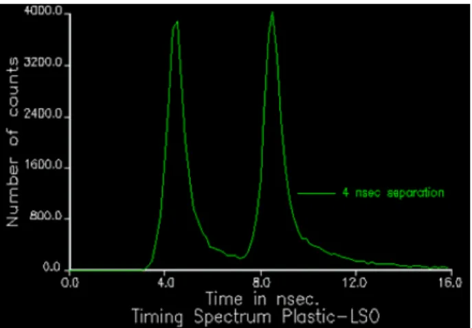
A another R-1635 PMT was coupled to a 2x2x10 mm polished LSO crystal which was placed 40 cm from the timing probe in order to mimic the geometry of a typical PET scanner but with very small crystals. This crystal size is used in the CPS high resolution research tomograph (HRRT)[12]. Timing spectra were acquired for 10 minutes with and without a 4 nsec. delay (corresponding to the time-of-flight effect when a rod source is at opposite points in its orbit). The full width at half maximum (FWHM) of the timing spectrum was measured using the time delay to calibrate the spectrum in psec./channel. In order to test the accuracy of the timing alignment obtainable with a short scan, 10 one minute acquisitions were made and the centroid of the timing spectrum was recorded in each experiment. This measurement was then repeated using ten minute acquisitions.
d) Timing performance of conventional PET detectors
In order to compare the single crystal results with what might be expected form a real scanner, two commercial PET detectors were substituted for the LSO detector. A BGO block detector from a CTI ECAT HR+ [6] with 64 crystal elements, and another BGO block detector from a General Electric (GE) Advance [10] with 36 crystal elements were
used. The signals from the four PMTs were amplified with separate channels of an ORTEC 574 timing amplifier and the outputs were summed with 50 Ohm resistors and coupled to the CFD. The CTI detector requires a positive bias, so the signals were decoupled with 0.1 :F capacitors. The PMT used in the timing probes, and the GE PET detector use negative bias, so the anode signal can be directly coupled. The timing of the whole block, and of individual columns of crystals were made.
e) Measurement of timing probe efficiency
The quantity of isotope used in the timing probes was measured during their manufacture at Isotope Products Laboratories (IPL) with a tolerance of 10%. The nominal activity was of all sources. The number of counts detected with a bias voltage of 1000 V, and the CFD threshold just above the noise level. The pulses were counted with a
Goldstar FC-2130 frequency counter. III.RESULTS
a) Signals from timing probes
Both isotopes produced satisfactory timing signals even though the maximum positron energy for 22Na is only 0.546 MeV compared with 1.9 MeV for 68Ge. This suggests that 22Na may be more economical to use in this application since its half life is 2.6 years. For both isotopes the plastic scintillator detected approximately 20-25% of the positron decays over a wide range of PMT high voltage settings. The results of all efficiency measurements are given in Table IV.
b) Intrinsic timing resolution
The intrinsic timing resolution of the TAC was measured to be 30 psec. The manufacturer’s specification on the TAC is equivalent to 7 psec. When the timing probe was connected to two separate channels of the CFD to timing jitter increased to 68 psec.
Isotope: 22Na 68Ge Max. positron
energy 0.546 MeV 1.9 MeV
Half-life: 2.6 years 270 days Prompt (
rays: 1.275 MeV none
T
ABLEIII C
HARACTERISTICS OF ISOTOPES USEDFigure 3 Timing spectrum with central source as start and small LSO crystal as stop inputs to TAC.
Figure 2 Delay in apparent arrival time for each row of crystals in two block detectors. The standard deviation in the arrival time is 1.1 nsec for both detectors.
c) Fast single crystal detector
The timing spectrum between a timing probe and small LSO crystal is shown as Fig. 2. The timing resolution was 850 psec.
Ten, 60 second acquisitions of the timing spectrum were made. The centroid of the timing peak occurred at 6002 ± 90 psec. When the acquisition time was increased to ten minutes the RMS spread in timing centroids improved from 90 to 60 psec.
d) Timing performance of conventional PET detectors
The whole block timing spectrum from the GE Advance, and HR+ detector had FWHM of 6.8 and 7.0
nsec. respectively. When the individual columns of crystals were compared, the times from the six and eight columns were compared there was a spread in the arrival times of 1.1 nsec. The results for both detectors are shown in Fig. 3.
e) Measurement of timing probe efficiency
The efficiencies of the four timing probes were in the range of 20 to 24%. The performance of the four probes is summarized in Table IV. In spite of having a lower positron energy, the 22Na probes appear to have a higher intrinsic efficiency.
f) Spectrum of LSO crystal
Figure 4 Shows the spectrum from a small LSO crystal with and without exposure to the gamma rays from 22Na. The peak at 1.275 MeV is clearly visible beyond the background radiation due to the invertible presence of 176Lu
IV DISCUSSION
Our results suggest that the use of a central timing alignment probe should provide a rapid measurement of the time offsets required for each detector in a PET scanner. In practise the timing alignment is performed rarely when a PET scanner is in routine use. Since it is a relatively long process and scanners timing seems quite stable, this seems satisfactory at present. However, little is known about the day-to-day drift of the time alignment with the accuracy to which the measurement appears possible with the timing probe presented here. In another paper presented at the meeting[1], we investigated the day-to-day timing stability of the Concorde Microsystems MicroPET R4. Its timing stability appears satisfactory for conventional PET studies when the time alignment is performed according to the manufacturer’s procedure.
With a renewed interest in the addition of time-of-flight information in the reconstruction of PET images[2], timing alignment will become much more critical. We feel that this new technique should provide a fast and accurate method of providing the time offsets required for any PET scanner which can accommodate input from the timing probe and should be especially valuable in maintaining a time–of-flight scanner.
Our technique has several advantages over current techniques. Presently timing alignment relies on the detection
of the pair of gamma rays, and testing different offsets to maximize the true counts detected by each crystal. This is inherently an iterative technique, since there is no time reference. Our technique detects the decay of the parent nucleus, and this becomes a reference time with respect to which all crystals are aligned. Since all crystals can be calibrated simultaneously, and the time reference is made very precise due to the fast decay time and brightness of the plastic scintillator.
One question which arose during the development of these timing probes is: “How often would one be used?” There performance suggests that they would be valuable in doing the initial timing alignment of a new scanner. They might also be useful as part of a scanner service kit and therefore used each time the scanner has a detector or component of the data acquisition electronics replaced. Another possibility would be to include a timing probe with every scanner. Presently many scanners use the performance of an unattended blank scan using the transmission sources, as both a daily quality control (QC) procedure and to provide the blank reference scan for the day’s transmission scans. However PET/CT scanners no longer need to acquire transmission scans. However some form of QC is still vital. Perhaps the timing probe could fulfil this role. It would have several advantages in this function: 1) It would provide the timing alignment as well as the detector’s relative efficiency. 2) If 22Na is used, its long half-life would require replacement only after two half-lives or five years thus providing a substantial operating economy. 3) again if 22Na is used, its high energy gamma ray is well beyond the background found in 176Lu. The 1275 KeV photo-peak is very conspicuous and would be useful for doing the energy calibration.
Our results suggest that the timing alignment could be acquired in one minute, with an accuracy more than required for TOF-PET. Even though the timing stability of modern PET scanners seems adequate for TOF[1], knowing that the timing alignment could be obtained in a one-minute scan would be added insurance that TOF data collected that day would be as precise as possible for every scan.
The timing probes use a very low activity source. In some places 10 :Ci sources of these isotopes can be held without a permit (less than one “scheduled quantity”)and this could be an advantage if this technique was used for the routine calibration of PET scanners. The source strength seems adequate based on the count-rate obtained even with these very small LSO crystals. The crystals used here were the same size as used in the HRRT scanner, however most scanners for human studies have crystals over ten times their volume so the count rate per crystal would be much higher.
VACKNOWLEDGEMENTS
We are very grateful to Lissa Zyromski of Isotope Products Laboratories Valencia Ca, for her help and suggestions in the manufacture of the positron emitting sources. The plastic scintillator was provided free of charge
by Frank Wilkinson of Alpha Spectra Inc, Grand Junction Co. The LSO sample crystals were provided by Matthias Schmand of CPS Innovations. Ernst Meyer, radiation safety officer at the Montreal Neurological Institute assisted with the regulatory issues relating to the importing, exporting and shipping of the timing probes.
VI REFERENCES
1. Thompson CJ, Goertzen, A: “Measurements on the timing stability of the MicroPET R4 animal PET scanner” IEEE MIC 2004 Paper #M5-30.
2. Moses W W: “Time of flight in PET revisited” IEEE Trans Nucl. Sci. 50:5 1325-1330 (2003) 3. Luo D, Williams J J, Limkeman M K, Cook M J,
Oswalt E L, McDaniel D L “Crystal-Based Coincidence Timing Calibration for PET Scanner” IEEE MIC Conference Record CD 2002_M11_060 4. Thompson C J, Lecomte R and Cadorette J: “Feasibility of Using Beta-Gamma Coincidence for 3D PET Attenuation Correction”. IEEE Trans. Nucl. Sci. 47(3) 1176-1181, (2000).
5. Camborde M-L, Thompson C J, Togane D, Zhang N: “A Positron Decay Triggered Transmission Source for Positron Emission Tomography” IEEE Trans. Nucl. Sci. 51:1 53-57 (2004)
6. Knoess C, Siegel S, Smith A, Newport D. Richerzhagen N, Winkeler A, Jacobs A, Goble RN, Graf R, Wienhard K, Heiss W D: “Performance evaluation of the MicroPET R4 PET scanner for rodents”. Eur J Nucl Med Mol Imaging. 30(5):737-47 (2003)
7. Brix G, Zaers J, Adam L E, Bellemann M E, et al. “Performance evaluation of a whole-body PET scanner using the NEMA protocol. National Electrical Manufacturers Association” J. Nucl. Med., 38(10):1614-1623, (1997).
8. Casey M E et al. “CPS HiRes: Pico electronics” J. Nucl Med (SNM abstract) June 2004
9. Thompson C J, and Camborde M-L: US Patent pending: “An instrument and method to facilitate and improve the timing alignment of a PET scanner”. (Application date, November 2002) 10. Lines K S, Grith T C, Heyland G R and Twomey T
R. “The decay rate of ortho-positronium in vacuum.” J. Phys. B: Atom. Molec. Phys.,
11(23):510–564, (1978).
11. Degrado T R, Turkington T G, et al., “Performance Characteristics of a Whole-Body PET Scanner”. J. Nucl. Med., 35(8):1398-1406 (1994).
12. Boellaard R, Buijs F H, de Jong W, Lenox M, et al. “Characterization of a single LSO crystal layer High Resolution Research Tomograph “, Phys. Med. Biol.