133
Md. Arif Istiek Neloy
a, Vicky Barua
b*, Mithun Das
c, Parthiba Barua
d, Shahid
Uddin Rahat
e, Abhijit Pathak
fa,b,c,d,e,f
Department of Computer Science and Engineering, BGC Trust University Bangladesh , Chandanaish -4382, Chattogram, Bangladesh
aEmail: [email protected] , bEmail: [email protected] cEmail: [email protected] , dEmail: [email protected] eEmail: [email protected] , eEmail: [email protected]
Abstract
Obstacle avoidance is an important task in robotics as the autonomous robot's aim is to reach the destination without collision. One type of autonomous robot that can detect obstacles and edges and take alternative paths free of obstacles and edges is a real-time obstacle avoiding edge detection robot. This paper proposes a robotic Robot with an intelligence built into it that guides itself whenever an obstacle comes along its way by bug algorithm. This robotic Robot is constructed using AT mega 8 families‟ micro-controller (Arduino Uno R3). The ultrasonic sensor is used to detect any obstacle with edges and sends a command to the microcontroller. The micro-controller, based on the received input signal, redirects the robot to push in an alternative direction by actuating the motors that are interfaced with it via a motor driver. Depending on the situation the robot is able to choose the correct path [1]. A decision making process of obstacle avoiding edge detection occurs spontaneously here. This robot was designed to think about its day-to-day potentialities.
Keywords: Arduino; Artificial Intelligence; Edge Detection; Obstacle Avoidance; Ultrasonic Sensor; Robotics.
--- * Corresponding author
134
1.IntroductionThe obstacle and edge detection robot is a decision-maker robot which can take its own decision depending on the real-time situation. If any obstacle or edge appears, it can sense it and take an alternative route free of obstacles or edges.
The following are some simple tasks that can be performed through the robot:
As long as it cannot locate an obstacle it pushes forward at constant speed and can sense a smooth surface instantly if it is put in front of it.
Similar to the obstacle it continues at constant speed until an edge is found. It can detect any kind of edge from a range of just 5 cm.
It has the ability to take rational decisions to find the best way to travel efficiently in its own way. Both the edge and the obstacle detection system will operate at the same time.
2.Prototype Design
The hardware needed to finish this project is as follows:
o Arduino Uno R3
o Motor Shield L293D
o 2x DC motors
o 3x Ultrasonic sonar sensor HC-SR04
o SG90 Micro Servo Motor
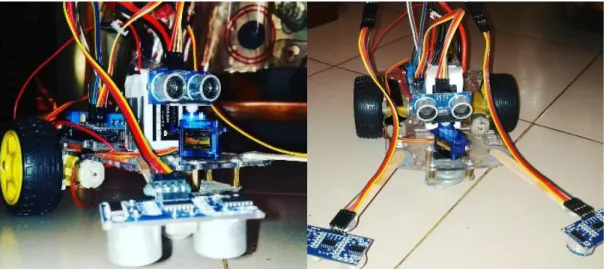
The system structure starts with a robot chassis kit that is driven by two wheels. The Arduino Uno R3 sits above the chassis, and the L293D motor shield aligns with the Arduino Uno R3. Two DC motors are attached in the motor shield slot m1 and m2. In the second slot the SG90 servo motor is connected. Three Ultrasonic sensors are connected to the motor shield in pins A0-A5. A lithium polymer ion battery powers the entire system. The jumper wires convey all necessary connections. The 11V lithium polymer ion battery was used because the motor shield needs a lot of power to work efficiently. The m1 and m2 slots used here to connect the DC motors. But user can use any of four slots to provide the connection. One thing to note here is that two ultrasonic sensors are used to detect the edge and spread slightly further from the robot with two simple extenders (user can use any kind of small stick or piece of metal or 3D printed arm). The third ultrasonic sensor is located above the servo motor (figure 1). Two ultrasonic sensors will be extended a little bit so the robot can stop while detecting the edge at the correct time. And because of the inertia, it takes some time to stop. The snapshots of the prototype are shown in the figure 1.
135
Figure 1: Snapshots of the Prototype
3.Technical Parts 3.1. Block Diagram
Figure 2: Block Diagram of the System
In the block diagram of the system, the Arduino Uno R3 sends a signal to the L293D motor shield that can control four dc motors at a time. Two servo motors can also be controlled by the motor shield. But here only two dc motors and one servomotor were used receiving signals from the shield of the motor [2]. And the motor shield receives the signal from ultrasonic sensors as the measuring distance. The overall system's block diagram is shown in figure 2 below.
136
Here motor shield L293D has been used for avoiding edge and hazard paths. It's like an interface between Arduino and the dc motors. It can manage 4 dc motors at a time. But only need two of these for this Robot. The motor 1 has been connected to the slot m1 and the motor 2 has been connected to the m2 slot of the motor shield. The L293D engine shield can also power to 2 servo motors at a time. Here one SG90 servo has been used which is connected to the 1st terminal for the servo motor. Moreover, three ultrasonic sensors have been used. Both ground and VCC pins from all ultrasonic sensors have been connected to the motor shield ground and 5V
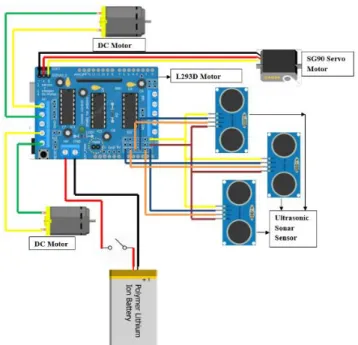
pin respectively. Ultrasonic 1 echo pin connected to A2 and A3 trig pin attached. For ultrasonic 2 echo pin linked to A1 and trig pin connected to A0. Ultrasonic 3 echoes and trigger pin connected to A4 and A5, respectively. 11V lithium polymer battery to power the entire device has been connected by a connection to the motor shield's external power supply terminal. In addition, the motor shield needed external power supply, and no additional power was necessary for the Arduino itself. The architecture of the system is shown in figure 3.
Figure 3: Architecture of the System
3.3. Working Principle of the system using Bug Algorithm
Primitive algorithms used to stop the robot to avoid the collision but modern techniques allow the robot to bypass obstacle using some form of quantitative calculation of obstacle dimensions. Primitive algorithms used to stop the robot to avoid the collision but modern techniques allow the robot to bypass obstacles using some form of quantitative measurement of the dimensions of obstacles [3].
137
(a)Bug 1 (b) Bug 2
Figure 4: Path Planning with Bug Algorithm [5]
The robot implements the steps below in the Bug 1 algorithm:
• The robot is bound for the destination.
• If the robot meets an obstacle, it circumnavigates it and stores / remembers how close it was to the target at each point.
• After circumnavigating the obstacle, the robot returns by wall-following to the point that is nearest to the obstacle and then continues on the route to the destination.
Figure 4(a) illustrates how a point robot uses the Bug 1 algorithm to navigate an area with two obstacles to reaching the target. The Bug 1 algorithm could be costly. If the cost of the straight line path from the beginning to the destination is D and the diameter of the obstacle is Pi, the distance d traveled by the robot is bounded by D= dD + 12 Pi. Therefore, the Bug 2 algorithm was proposed to avoid circumnavigating the obstacle [6].
The robot follows the following steps within the Bug 2 algorithm:
• The robot heads towards the m-line destination, which is identified as the line that joins the starting location and the destination.
• If an obstacle is detected, the robot will pursue it until the time it finds the m-line closer to the target again.
• The robot then leaves the obstacle and starts on the m-line again towards the target.
Figure 4(b) illustrates how a point robot uses the Bug 2 algorithm to traverse an area with two obstacles to reach the destination. It would be more cost-effective if the robot could travel directly to the destination as soon as a straight line path from its present position to the destination becomes feasible. Bug 1 is therefore an exhaustive search algorithm as it looks at all choices but Bug 2 is a greedy algorithm. Bug 2 outperforms Bug 1 in many instances, but Bug 1 does have a more predictable efficiency. Nevertheless, in the real world, we have sensors
138
such as range sensors that are more powerful than a touch sensor and can look ahead to a limited range [4]. Then we implement the Tangent Error algorithm. Here, the working principle has given below:
Step 1: Start
Step 2: Initialization
Step 3: Is there any obstacle or edge?
(a) If yes, go to step 5
(b) No, run the robot in forward direction
Step 4: If there is any obstacle or edge found
(a) Yes, move backward
(b) No, go to step 3
Step 5: Distance measurement to turn left or right
If right distance > left distance
(a) Yes, turn right
(b) No, turn left
Step 6: Continue Step 3
Step 7: If power failed go to step 8
Step 8: Stop
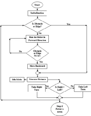
3.4. System Flowchart
The flowchart of the system is given in figure no 4.
It displays the route taking obstacle decisions in the upper flow chart, avoiding with edge detection robot. Unless we start from the start, the robot will not start movement first of all after turning the power on. The first thing that it will do after initialization is to look for an obstacle or an edge before it. When there is no barrier or edge the robot can step forward freely. And it'll look for challenge and edge in every moment in its way of moving forward. It will push along easily, as long as there are no gaps and edges. It will take the same action, regardless of when faced with the challenge or bottom.
139
Figure 5: Flowchart of the system
It could be right at the beginning of its journey, or in the middle of the path. For some space, the first thing that it will do after detecting an obstacle or edge comes backward (3 cm). The obstacle detection range is 15 cm which may be modified depending on the robot's speed. It will stop and look right and left respectively, after going backward. Looking right and left here means measuring the distance between right and left via an ultrasonic sensor. Based on the room on the right or left, the robot will move to the side which has the more space than the other. Then, it will continue its procedure again from the very beginning. A question arises here. What will happen if the two distances are the same? With one-tenth of a meter of distance ultrasonic measurements, this is most likely not going to happen. Now let's get into another portion, what if an edge is detected? The robot will follow the same procedures for obstacles. Whenever an edge is detected, it stops, returns backward and turns to the right or to the left depending on the greater distance and continues to move forward until it finds another obstacle or edge. There is no risk of slipping or falling from the top for searching the edges and obstacles. Here we never have to apply the pressure to find the side where there is no edge, the robot will stop anyway when it senses an edge.
3.5. Decision Making Process through Distance Measurement
The table 1 below shows when the robot will stop and when it will move forward based on the value of the distance measurement which it will get from three ultrasonic sensors.
140
Table 1: Decision Making Process through Distance Measurement
Right Ultrasonic Value Left Ultrasonic Value Middle Ultrasonic Value Decision
<5 cm ≥5 cm >15 cm Stop Robot <5 cm ≥5 cm ≤15 cm Stop Robot <5 cm <5 cm >15 cm Move Forward <5 cm <5 cm ≤15 cm Stop Robot ≥5 cm ≥5 cm >15 cm Stop Robot ≥5 cm ≥5 cm ≤15 cm Stop Robot ≥5 cm <5 cm >15 cm Stop Robot ≥5 cm <5 cm ≤15 cm Stop Robot
One thing to note here again is that Ultrasonic Sensors right and left, both facing down to detect the edge and for detecting obstacles the middle ultrasonic sensor faces forward. When the right and left ultrasonic sensor has a value of more than or equal to 5 cm, the robot will take it as an edge and start searching for an alternative path. And when the reading of the ultrasonic sensor in the front of the middle face is less than 15 cm, the system can consider it an obstacle and immediately stop the Robot. When we look through the entire table we will see that there is only one sweet spot where the Robot can push forward. The sweet spot is when the mean ultrasonic value is greater than 15 cm with an ultrasonic right and left sensor value less than 5 cm.
3.6. Path Planning to Detect Obstacle and Edge
Figure 5 demonstrates the robot's route planning with obstacles and boundaries.
Figure 6: Path Planning of the Robot with Obstacles and Edges
141
and eventually it will detect obstacle 4. And the algorithm will once again help it turn left and reach the goal.
4.Applications
There is an immense amount of obstacle and edge potential avoiding robots in different sectors. The following are some significant ones:
• From Bangladesh's perspective, most of the rural roads are without a guardrail. That's why there is always a risk that it will fall through the edge. This module can be integrated into the Robot and will help to deal with unwanted incidents.
• In the case of multi-story building construction, different building materials falling from unfinished floors are quite normal. Such products can be transported very easily across the edge.
• From the perspective of Bangladesh, most of the roads through the mountains don‟t have any guardrail. That‟s why there is always a risk of falling through the edge. This module can be equipped in the Robot and it will help to face uninvited accidents.
• In the case of multistoried building construction, it is pretty common, falling various construction materials from incomplete floors. These materials can be carried very efficient through the edge and obstacle avoiding robot.
• There are a lot of disable people depended on wheelchair. This idea can be implemented in wheelchairs as it can detect obstacle and edge autonomously.
5.Limitations
As ultrasonic sensor measures the distance through ultrasonic sound, sometimes it becomes difficult for the robot to measure the distances accurately due to rough edges. It can lead to wrong decisions. That's why when we are using ultrasonic sensors the obstacles and edges have to be as smooth as possible. This problem may not occur if we use IR sensor instead of ultrasonic sensors. But we do prefer ultrasonic sensor as IR sensors are sensitive to light. Again if any obstacle is located under the range of the front ultrasonic sensor, it is most likely to avoid the obstacle. The robot can overcome this limitation if the ultrasonic sensor is placed very close to the surface. The last point is, this prototype has not been designed to go through any slop. It should be designed differently to overcome this limitation.
142
6.Future Recommendations If the current project is interfaced with a camera robot it is possible to drive beyond line of sight & range as networks have a very wide range.
Use as a firefighting robot: We can use this robot as a firefighting robot by adding temperature sensor, water tank and making some programming changes.
We will extend this project by IR (or) RF (or) ZIGBEE using wireless technology.
Use of the mobile phone we can use the DTMF receiver.
This robot can be used to select and position the appropriate object by giving the robot directions but it should remove the ultrasonic sensor depending on the application.
7.Future Works
An essential area of robotics research is enabling robots to adapt to their environment. Whether this is an underwater environment, on land, underground, in the air or in space.
A fully autonomous robot is capable of working
• Work for an extended period of time without human intervention or a power supply requirement. • Evite harmful circumstances.
The most effective method to increase my robot's accuracy is to include better sensors, although the cost of the project may increase but the accuracy will definitely increase as well as the space of problem where the robot can be used. Better actuators will make robot faster and more efficient
8.Conclusion
This project‟s aims at creating an autonomous robot that intelligently detects the obstacle in its path and navigates according to the behavior we are setting for it The above Arduino controller and ultrasonic sensor have been studied and the ultrasonic sensor has been selected as the control result has been developed to satisfy its use in the car prototype system. The main task was used to sense the obstacle and avoid it. By coding the algorithm in C, successfully implementing the obstacle avoidance algorithm was also achieved with minimal errors. Obstacle avoidance is a very useful technique which can be used in cars to prevent many accidents and life losses.
References
[1] Khatib, O., Real-Time Obstacle Avoidance for Manipulators and MobileRobots,. 5, 1986. The International Journal of Robotics Research: p. 90-98.
143
[5] Buniyamin N., Wan Ngah W.A.J., Sariff N., Mohamad Z., “A Simple Local Path Planning Algorithm for Autonomous Mobile Robots”, INTERNATIONAL JOURNAL OF SYSTEMS APPLICATIONS, ENGINEERING & DEVELOPMENT, Issue 2, Volume 5, 2011
![Figure 4: Path Planning with Bug Algorithm [5]](https://thumb-us.123doks.com/thumbv2/123dok_us/10944059.2983003/5.892.123.787.109.307/figure-path-planning-with-bug-algorithm.webp)