Study on heat integration of supercritical coal-fired power plant
1with post-combustion CO
2capture process through process
2
simulation
34
Xiaoyan Liu
a, Jian Chen
a,*, Xiaobo Luo
b, Meihong Wang
b,*,
Hui Meng
b 5a
State Key Laboratory of Chemical Engineering, Tsinghua University, Beijing 100084, China 6
b
Process and Energy Systems Engineering Group, School of Engineering, University of Hull, HU6 7
7RX, UK 8
*Corresponding author 1. Tel: +86 10 62798627; Fax: +86 10 62770304; Email: [email protected]
9
*Corresponding author 2. Tel: +44 1482 466688; Fax: +44 1482 466664; Email: [email protected]
10 11
Abstract 12
Coal-fired power plant (CFPP) is one of the main sources of anthropogenic CO2 emissions. Capturing CO2 13
from CFPP by post-combustion process plays an important role to mitigate CO2 emissions. However, a 14
significant thermal efficiency drop was observed when integrating CFPP with post-combustion carbon
15
capture (PCC) process due to the steam extraction for capture solvent regeneration. Thus research efforts
16
are required to decrease this energy penalty. In this study, a steady state model for 600 MWe supercritical 17
CFPP was developed as a reference case with a low heating value (LHV) based efficiency of 41.6%. A
18
steady state model for MEA-based PCC process was also developed and scaled up to match the capacity of
19
the CFPP. CO2 compression process was simulated to give an accurate prediction of its electricity 20
consumption and cooling requirement. Different integration cases were set up according to different
21
positions of steam extraction from the CFPP. The results show that the efficiency penalty is 12.29% and
22
14.9% when steam was extracted at 3.64 bar and at 9.1 bar respectively. Obvious improvements were
23
achieved by utilizing waste heat from CO2 capture and compression process, taking part of low pressure 24
cylinders out of service, and adding an auxiliary turbine to decompress the extracted steam. The efficiency
25
penalty of the best case decreases to 9.75%. This study indicates that comprehensive heat integrations can
26
significantly improve the overall energy efficiency when the CFPP is integrated with PCC and
27
compression process.
28 29
Keywords: process simulation; heat integration; supercritical coal-fired power plant; post-combustion CO2 30 capture; CO2 compression. 31 32 1. Introduction 33
Greenhouse gases emissions have been on the increase since the start of industrial revolution. CO2 is the 34
main greenhouse gas accounting for over 60% of total greenhouse gas emissions [1]. The
35
Intergovernmental Panel on Climate Change (IPCC) indicates that CO2 emissions need to be cut by a 36
minimum of 50% to limit the average global temperature increment to 2°C in 2050 [2]. Carbon capture and
37
storage (CCS) is considered the key technology to mitigate CO2 emissions from fossil fuel-based power 38
generation.
39
A great portion of CO2 emissions is generated from the electricity and heat industry. Coal combustion is 40
estimated to be the largest source of electricity and heat generation, particularly in South Africa (93%),
41
Poland (92%), China (79%), India (69%), and United States (49%) [3, 4]. The majority of existing CFPPs
42
are based on subcritical steam cycles, however, supercritical CFPPs are rapidly spreading to replace
43
subcritical CFPPs, with advantages of higher thermal efficiency and lower CO2 emissions [5, 6]. The 44
average thermal efficiency of subcritical CFPPs is 35%, while supercritical CFPPs have about 5%pt higher
45
net efficiency [7]. Supercritical CFPPs would play an important role in global power generation and the
46
reduction of coal consumption.
47
Monoethanolamine (MEA)-based chemical absorption technology remains the first choice for CFPP due
48
to its high operational flexibility because it can be easily integrated into both the existing power plants and
49
new installations [8]. Moreover, this technology is characterized by a relatively high separation selectivity
50
[9-12], so that it is well-suited for treating low CO2 partial pressure flue gas from CFPP [13]. 51
Previous studies [14-16] indicates that there is a significant energy penalty when CFPP is couple with
52
PCC process, because of the steam extraction from CFPPs for solvent regeneration. This high energy
53
penalty constitutes the main barrier of the commercial deployment of CCS technology. There are two
54
solutions to reduce the energy penalty: (1) improving the performance of PCC process, or (2) retrofitting
55
the steam cycle of power plant with comprehensive heat integrations with PCC process.
56 57
The absorption process has been extensively researched to decrease its reboiler duty. Freguia and
58
Rochelle [17] performed sensitivity analyses on process variables to find operating conditions at low
59
energy requirement. Moullec et al. [18] and Babatunde et al. [19] evaluated various process modifications 60
through modelling and simulation. A variety of single solvents and blended solvents are studied and compared 61
to find advanced solvents possessing good performance and low price [20-22]. These processes are run in the 62
scale of pilot plant, however, another difficulty of commercial application of PCC technology in CFPP is to 63
evaluate the performance of PCC plants in industrial scale. Lawal et al. [16] scaled up the process according to 64
chemical engineering principles to match a specific CFPP. 65
Several other researchers focus on the thermal efficiency of CFPPs to improve the steam conditions in boiler. 66
Weitzel et al. [24] improved the overall CFPP thermal efficiency by 6% through adopting 700 ℃ technology in 67
steam generator instead of 600 ℃ technology. However, the steam conditions are related to the materials in
68
steam generator, critical steam piping and steam turbine. Thus this method is infeasible for retrofits of existing
69
CFPPs. One main strategy is recovering the waste heat of PCC plant to heat circulating water, which contributes
70
to a reduction of steam extraction for solvent regeneration. Hanak et al. [3] reduced the efficiency penalty by
71
0.43% through heat exchanger network (HEN) analysis. In the study of Gibbins and Crane [25], extracted steam
72
is desuperheated through exchanging heat with part of the reboiler condensate, and waste heat from CO2 capture 73
and compression process is recovered by heating circulating water, decreasing the efficiency penalty by 2.9%
74
for MEA and by 2.5% for KS-2. Besides, Lucquiaud and Gibbins [26] compared three capture ready steam
75
turbine options (clutched LP turbine, throttled LP turbine and Floating IP/LP crossover pressure), revealing that
76
the case with clutched LP turbine presented lowest efficiency penalty.
77
Based on above research, this paper focuses on the integration of steam cycle and PCC plant,
78
comprehensively considering heat exchanger network analysis, utilization of the superheat of extracted
steam, capture ready steam turbine options and steam-extraction locations. To do this, the steam cycle of a
80
600MWe supercritical CFPP was modelled and simulated, as well as the CO2 capture and compression 81
process. The CO2 capture process is scaled up to match the capacity of the 600MWe supercritical CFPP. 82
Furthermore, eight cases were simulated and compared regarding the energy efficiency improvement.
83
Two novelties can be claimed for this paper: 1) detailed study on scale-up of PCC process to match the
84
flue gas flowrate of a specific 600 MWe supercritical CFPP was performed. 2)comprehensive heat 85
integration options were studied for two different stream extraction from LP I (at 3.64 bar) and IP-LP
86
crossover (at 9.1 bar) respectively for solvent regeneration. Compared with previous studies such as Lawal
87
et al. (2012) [16], this study considered not only how to extract steam from steam turbine in power plant
88
for PCC reboiler, but also heat integrations between PCC, CO2 compressors and CFPP. More important is 89
that these possibilities have been combined in the case study.
90 91
2. Model development 92
2.1. Model development of Supercritical CFPP 93
94
Selected as the reference power plant was a 600 MWe supercritical CFPP (24.2 MPa/571℃/569℃) in 95
China (Figure1), in which approximately 1677.5t/h of high-pressure steam generated in the steam
96
generator passes through HP, IP, and LP turbines successively for electric power generation. In this power
97
plant, the exhausted steam is next condensed to water in the condenser at pressure of 0.0588bar, and
eight-98
stage steam (HP I & HP II; IP I & IP II; LP I, LP II, LP III & LP IV) is drawn off to heat the circulating
99
water (see Table 1). The first three-stage steam extraction is for HP feedwater heaters; the fourth-stage
100
steam extraction is for deaerator; and the last four-stage steam extraction is for LP condensate heaters. In
101
addition, fuel combustion produces a large amount of flue gas. Before entering the CO2 capture process, 102
flue gas is often treated with a series of chemical processes and scrubbers to remove particulate matter
103
and sulphur dioxide.
104
This supercritical CFPP is modelled in Aspen Plus® as base case to explore the influence of PCC
105
integration. The STEAMNBS property method is used to properly evaluate the steam process. All turbines
106
are simulated using Compr blocks set as isentropic turbines, and circulating water heaters are modelled as
107
HeatX blocks [23]. The boiler is replaced as a HeatX block to simplify the process. The overall
108
performance is shown in Table 2.
109 110
2.2. Model development and scale-up of PCC process 111
2.2.1. PCC process description 112
Figure 2 shows a typical CO2 chemical absorption process. CO2 from flue gas is chemically absorbed by 113
an MEA solution in the absorber column and then released from the top of the regenerator column with
114
high concentration. In this study, a closed-loop rate-based CO2 absorption model is developed in Aspen 115
Plus® and validated using the data from a pilot plant at University of Texas, Austin [27, 28]. All
116
parameters in the model and validation process are stated by Canepa, et al [23]. In the pilot plant, both the
absorber and regenerator column are 0.427m in diameter and packed with two sections of 3.05m packing.
118
The absorber is operated at atmospheric pressure with a random metal packing, IMTP no.40, while the
119
regenerator is operated at apressure of 1.7 bar and filled with a structured packing, Flexi Pac1Y.
120 121
2.2.2. Model scale-up 122
To match the capacity of a 600 MWe supercritical CFPP, the CO2 capture plant model has been scaled 123
up based on chemical engineering principles. As an initial input of Aspen Plus® model, a first-guess
124
diameter is required for the absorber and the regenerator. One engineering practice is to calculate the
125
column diameter from the maximum flooding vapour velocity which could be estimated by empirical
126
correlation equations and figures. In this study, a generalised pressure drop correlation figure (see Figure
127
11.46. in [29]) adapted from a figure by the Norton Co. was used. The abscissa and ordinate are presented
128
in Equation (1) and Equation (2) respectively [29].
129 130 * * w V LV w L
L
F
V
ρ
ρ
=
(1) 131 * 2 0.1 413.1(
)
(
/
)
(
)
w p L L V L VV
F
K
µ
ρ
ρ
ρ
ρ
⋅
⋅
=
−
(2) 132FLV is a flow parameter which is related to L/G ratio; K4 is a modified load which is evaluated from Figure 133
11.46. in [29] according to the value of FLV and assumed pressure drop. Fp is a packing factor. Based on 134
this, V*w (vapour mass flow rate per unit cross-sectional area) is calculated, then the total cross-sectional 135
area can be obtained given the flue gas flow rate. This methodology has also been applied in numerous
136
similar literatures [3, 16, 23].
137
Flooding and minimum liquid load are two primary limitations for the operating region of packed
138
columns. Flooding defines the upper operating line of packed column. The minimum liquid load is set to
139
ensure that the entire packing surface is wetted [16, 30]. In order to achieve good liquid and gas
140
distribution, pressure drop between 15 and 50 mmH2O per meter packing for absorber and regenerator 141
columns was recommended [29]. In this paper, pressure drop of 42 mmH2O per meter packing is selected 142
for the scale-up [3]. Here one important thing should be noticed that the design of the column internals
143
such as gas/liquid distributors and re-distributors is crucial to ensure good gas and liquid distribution inside
144
the absorber and regenerator in such large diameters.
145
The boundary conditions data can be seen in Table 3. A first-guess diameter of the absorber and
146
regenerator can be calculated using the above method. Starting from this, these parameters will be
147
improved in the development of the closed-loop CO2 absorption model in Aspen Plus ®
. In the simulation
148
of the closed-loop capture plant, lean loading (mol CO2/mol MEA) is an important parameter related to 149
reboiler duty. The change of reboiler duty at different lean loadings is presented in Figure 3; here it can be
150
seen that the reboiler duty first decreases as lean loading increases, and then it increases with the increase
151
of lean loading. Minimum reboiler duty is attained when lean loading is 0.23 mol CO2/mol MEA. 152
The relationship of different numbered columns and diameters is given in Figures 4 and 5. Considering
153
structural limitations, it is better to keep the column diameter less than 12.2m—thus, for the absorber, at
154
least three columns with diameters of 11.66m are needed [16, 31] whilst a two-column regenerator with a
155
diameter of 10.78m is selected. The overall performance of the capture plant with improved parameters is
156
shown in Tables 4 and 5.
157 158
2.3. Simulation of compression process 159
After the CO2 captured from the power plant, it will be pressurized at a pressure as high as 110 -150 bar 160
for pipeline transport and geologic sequestration [32, 33]. Thus a compression train is needed. In this study,
161
CO2 is pressurized to 90 bar by a four-stage compressor and then pressurized to 110bar by a pump. 162
Between two adjacent stages of the compressor, an intercooler cools the stream. A flash tank is set after the
163
intercooler of the first stage and second stage to draw off liquid water (Figure 6). In the simulation,
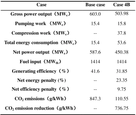
164
isentropic compression model is selected with 90% isentropic efficiency [18]. And the pressure drop of
165
intercoolers is assumed as 2% [34]. Simulation results are given in Table 6. There are four hot streams that
166
need to be cooled in the process, and the heat can be integrated into the steam cycle.
167 168
3. Integration of CFPP with PCC and compression process 169
170
A large amount of steam is drawn off from steam cycle to heat the reboiler because of the huge energy
171
required for solvent regeneration, as shown in Figure 7. In this way, all of the low-pressure condensate
172
heaters are removed, and a throttling valve (V1 in Figure 7) is added at the steam extraction location to
173
ensure the plant’s stability [35]. The solvent regeneration temperature in the reboiler of the capture plant is
174
120℃, meaning that hot steam used to heat the reboiler should be 130℃with 10℃ mean temperature
175
difference—that is to say that steam of 2.7 bar is required for solvent regeneration. However, the steam
176
extraction point is not casual; Table 1 details the eight stages of steam extraction in the steam cycle.
177
Consequently, the steam drawn off for solvent regeneration is usually decompressed to 2.7 bar by a
178
throttling valve V2 and cooled down to just above saturated temperature through transferring heat with
179
circulating water in H4. The power plant without PCC process has been simulated as the Base Case in
180
Section 2.2. In this section, this study focuses on the effect of PCC plant integration on power plant
181
performance.
182 183
3.1. Steam extraction from LP I (i.e. 3.64 bar) 184
3.1.1. Considerations 185
For the location selection of steam extraction for solvent regeneration, LP I (at 3.64 bar) is appropriate
186
because it is closest to 2.7 bar as seen in Table 1. After the steam is drawn from LP I, the steam is
187
decompressed to 2.7 bar and then cooled to its saturated state before entering the reboiler in PCC process.
188
In the steam cycle, thermal energy is needed to heat circulating water. In general, this energy is provided
189
by eight-stage steam extraction for a standalone CFPP. Once CFPP is integrated with CO2 capture and 190
compression process, energy saving could be achieved by coupling the hot streams of capture and
191
compression process with the steam cycle to heat circulating water. The properties of hot streams are
192
presented in Table 7. The stream named ‘CO2 cooling’ is from the last compressor and required to be 193
condensed to enter a pump. It should be noted that the heat load of the stream shown here does not involve
194
the heat of condensation because the condensation temperature is too low to be utilized. The highest
195
temperature of hot streams in Table 7 is 167℃ whilst circulating water is heated from 34℃ to 175.9℃ in
196
LP condensate heaters and then is heated from 175.9℃ to 272℃ in HP feedwater heaters. Therefore, only
197
circulating water in the low-temperature section can be heated by waste heat from CO2 capture and 198
compression process.
199 200
Moreover, a great amount of steam is drawn off for solvent regeneration; thus a throttling valve is
201
generally added to keep the stability, resulting in a throttling loss. On the other hand, there are usually
202
several sets of LP cylinders in the plant to avoid the turbine blade becoming too long when steam
203
expanding in power generation process. Consequently, if part of the LP turbine is taken out of service, the
204
rest LP turbine can work at conditions close to normal operating state; accordingly, the throttling loss is
205 avoided. 206 207 3.1.2. Case studies 208
For the scenario of steam extraction from LP I stream (3.64 bar) for solvent regeneration, three cases are
209
set up to study the effect of utilizing waste heat and taking part of the LP turbine out of service in below:
210
Case 1A: Basic integration of PCC into supercritical CFPP with steam extraction from LP I for PCC
211
reboiler.
212
Case 2A: Utilizing waste heat from the PCC and CO2 compression process for feedwater pre-heating in 213
CFPP & steam extraction from LP I in CFPP for PCC reboiler.
214
Case 3A: Taking part of LP cylinders out of service & Utilizing waste heat from the PCC and CO2 215
compression process for feedwater pre-heating in CFPP & steam extraction from LP I in CFPP for PCC
216
reboiler.
217
These three cases are set progressively, and the flow chart of case 3A is shown in Figure 8. In the
218
process of waste heat utilization, ∆T for heat transfer is set to 10℃. The circulating water is heated to 74℃
219
by the condenser of regenerator first, then it is divided into four parts and exchange heat with the four
220
intercoolers of compression process respectively, as a result, the four streams are heated to 138℃, 125℃,
221
131℃ and 157℃ respectively, and the average temperature is 139℃. So that the effect of PCC integration
222
can be investigated, the performance of the cases is presented as net power output, generating efficiency
223
and CO2 emissions, and compared with the base case described in section 2.2.Simulation results 224
comparison between these three cases and the base case are given in table 8. Generally introduction of the
225
CO2 capture process results in a large efficiency penalty in the supercritical CFPP. In Case 1A, the 226
efficiency penalty is 12.29% points and equals a decrease of 29.5% in the economic benefits of the power
227
plant. Waste heat is recovered in Case 2A, which makes an improvement of 0.54% points in generating
efficiency. This is because waste heat utilization decreases the flow rate of steam extraction for circulating
229
water heating. Furthermore, more than half of the LP steam is drawn off, and a throttling valve is added to
230
ensure the power plant stability. However, if half of the LP turbine is taken out of service, the other half
231
can still work in approximately normal condition; therefore, the throttling loss is avoided. The power plant
232
performance is shown in case 3A in which generating efficiency is improved by 0.9% after taking half of
233
the LP turbine out of service. Moreover, for new power plants, the capacity of every LP cylinder can be
234
designed according to the flow rate of steam extraction, which allows the corresponding LP cylinder to
235
shut down when integrating with PCC.
236 237
3.2. Steam extraction from IP-LP crossover (i.e. 9.1 bar) 238
3.2.1. Considerations 239
The overall performance of the power plant with steam extraction from LP I (i.e. 3.64 bar) was studied
240
in Section 3.1. Theoretically it is feasible to draw steam from any stage of steam turbine with pressure
241
higher than 2.7bar for solvent regeneration. However, it is not economical to draw steam when steam
242
pressure is too high considering the large throttling loss. As a typical case, we study steam extraction from
243
IP-LP crossover with steam pressure at 9.1 bar. The consideration of setting up Cases 1B, 2B and 3B is
244
similar to what has been analysed in Section 3.1.
245 246
3.2.2. Case studies 247
Three cases are developed to compare the performance of power plant with 9.1 bar steam extraction:
248
Case 1B: Basic integration of PCC into supercritical CFPP with steam extraction from IP-LP crossover
249
for PCC reboiler.
250
Case 2B: Utilizing waste heat from the PCC and CO2 compression process for feedwater pre-heating in 251
CFPP & steam extraction from IP-LP crossover in CFPP for PCC reboiler.
252
Case 3B: Taking part of LP cylinders out of service & Utilizing waste heat from the PCC and CO2 253
compression process for feedwater pre-heating in CFPP & steam extraction from IP-LP crossover in CFPP
254
for PCC reboiler.
255
In Case 2B and Case 3B, the temperature of the steam, which is freshly decompressed from 9.1 bar
256
steam, is too high to be cooled down to the saturated temperature by preheated circulating water. For such
257
a situation, part of the steam cooled down in the reboiler is returned back to mix with high-temperature
258
steam to effect the appropriate temperature, as shown in figure 9. In this way, less steam is drawn off and
259
more is used to generate electricity. Meanwhile, more condensate is produced from the condenser,
260
resulting in that waste heat from PCC plant is not able to improve the circulating water to the same
261
temperature in Case 3A. In the heat exchanger network, circulating water is heated to 74℃ first, then it is
262
divided into four streams which are heated to 133℃, 115℃, 127℃ and 152℃ respectively, the average
263
temperature is 133℃. The overall performance of these cases is presented in table 9.
264
From results (for steam extraction at IP-LP crossover) shown in Table 9, the net efficiency penalty in
265
Cases 1B, 2B and 3B are 14.9%, 14.04% and 13.0% respectively. However from results (for steam
extraction at LP I) shown in Table 8, the net efficiency penalty in Cases 1A, 2A and 3A are 12.29%, 11.75%
267
and 10.85% respectively. By comparison, steam extraction at lower pressure is more economical. This can
268
be explained theoretically that the throttling loss of decompressing higher pressure steam (9.1 bar) to 2.7
269
bar is more serious. On the other hand, the reduction of efficiency penalty from Case 1B to Case 3B (1.9%)
270
is lightly higher than it from Case 1A to Case 3A (1.44%). This is because the 9.1 bar steam saved in Case
271
3B due to heat integration is higher grade stream, resulting in a higher power output increment.
272 273
3.3. Auxiliary turbine 274
275
From Section 3.1 and Section 3.2, the net power output is improved through utilizing waste heat and
276
taking half of LP turbine out of service. However, the throttling valve V2 is still causing energy loss,
277
especially in Case 3B. In this section, the addition of an auxiliary turbine to decompress the steam
278
extracted from IP-LP crossover at 9.1 bar is considered. The throttling valve V2 is no longer necessary. As
279
this case is a further extension of Case 3B, this case is called Case 4B:
280
Case 4B: adding an auxiliary turbine (see Figure 10) to decompress the extraction steam & taking part of
281
LP cylinders out of service & utilizing waste heat from the PCC and CO2 compression process for 282
feedwater pre-heating in CFPP & steam extraction from IP-LP crossover in CFPP for PCC reboiler.
283
In Case 4B, the steam decompressed by the auxiliary turbine possesses less superheat to heat circulating
284
water and reboiler condensate. Thus more 9.1 bar steam than that in Case 3B is extracted to match the
285
reboiler duty, resulting in less condensate from condenser. In this way, circulating water from condenser is
286
able to be heated to higher temperature than that in Case 4B through waste heat recovery. Specifically, the
287
circulating water from condenser is heated to 74℃ first, then it is divided into four streams which are
288
heated to 138℃, 125℃, 131℃ and 157℃ respectively. The average temperature is 139℃. The
289
performance can be seen in Table 10. The net efficiency penalty in Case 4B is 9.75%, this result
290
demonstrates a substantial improvement of a 4% increment compared with Case 3B. Thus it can be seen
291
that the throttling loss in Case 3B is huge. The net efficiency penalty in this case is 9.75%, 1.1% points less
292
than it in Case 3A. Among all cases presented, Case 4B represents the best performance.
293 294
4. Conclusions 295
296
In this study, a steady state model for 600 MWe supercritical CFPP was developed, and seven cases were 297
studied to investigate the effect of integration with PCC process and CO2 compression process. Generating 298
efficiency for the reference case is 41.6%. It reduced to 29.31% when more than half of the steam was
299
extracted from LP I (at 3.64 bar) for solvent regeneration. Two methods, utilization of waste heat from
300
PCC process and CO2 compression process and taking half of LP turbine out of service, were adopted to 301
decrease the efficiency penalty, which improved the generating efficiency to 30.75%. Similar study was
302
performed in the cases of extracting steam from IP-LP crossover at 9.1 bar. The generating efficiency
303
reduced to 26.7% in the basic integration, and improved to 28.6% through adopting the two methods.
304
Extracting steam from IP-LP crossover at 9.1 bar caused more serious efficiency penalty due to the higher
throttling loss. However, an auxiliary turbine was added to decompress the 9.1 bar steam, which
306
contributed to a reduction of 3.25% in efficiency penalty. In this way, net generating efficiency is 31.85%
307
and the efficiency penalty is reduced to 9.75%. According to the results, comprehensive heat integration
308
modifications can effectively reduce the energy penalty when the CFPP is integrated with PCC and CO2
309 compression process. 310 311
Acknowledgement
312 313The authors would like to acknowledge the financial support from the National Natural Science
314
Foundation of China (key project No. 51134017), EU FP7 Marie Curie International Research Staff
315
Exchange Scheme (Ref: PIRSES-GA-2013-612230) and State Key Laboratory of Chemical Engineering of
316 China (SKL-ChE-12Z01). 317 318
References
319[1] IPCC. Climate change 2014: mitigation of climate change: contribution of working group III to the fifth 320
assessment report of the intergovernmental panel on climate change. Cambridge, United Kingdom and 321
New York, NY, USA: Cambridge University Press; 2014. 322
[2] IPCC. Managing the risks of extreme events and disasters to advance climate change adaptation. 323
Cambridge, United Kingdom and New York, NY, USA: Cambridge University Press; 2012. 324
[3] Hanak DP, Biliyok C, Yeung H, Białecki R. Heat integration and exergy analysis for a supercritical high-ash 325
coal-fired power plant integrated with a post-combustion carbon capture process. Fuel 2014; 134: 126-326
139. 327
[4] IEA. Energy technology perspectives 2010: scenarios & strategies to 2050. Paris, France: IEA Publications; 328
2010. 329
[5] IEA. Technology roadmap: carbon capture and storage. Paris, France: IEA Publications; 2013. 330
[6] IEA. Tracking clean energy progress 2013: IEA input to the clean energy ministerial. Paris. France: IEA 331
Publications; 2013. 332
[7] Goto K, Yogo K, Higashii T. A review of efficiency penalty in a coal-fired power plant with post-combustion 333
CO2 capture. Applied Energy 2013; 111: 710-720. 334
[8] Wang M, Lawal A, Stephenson P, et al. Post-combustion CO2 capture with chemical absorption: A state-of-335
the-art review. Chemical Engineering Research and Design 2011; 89:1609-1624. 336
[9] Alie C, Backham L, Croiset E, Douglas PL. Simulation of CO2 capture using MEA scrubbing: a flowsheet 337
decomposition method. Energy Conversion and Management 2005; 46: 475-487. 338
[10] Kanniche M, Gros-Bonnivard R, Jaud P, et al. Pre-combustion, post-combustion and oxy-combustion in 339
thermal power plant for CO2 capture. Applied Thermal Engineering 2010; 30: 53-62. 340
[11] Rao AB, Rubin ES. A technical, economic, and environmental assessment of amine-based CO2 capture 341
technology for power plant greenhouse gas control. Environmental science & technology 2002; 36: 4467-342
4475. 343
[12] Singh d, Croiset E, Douglas PL, Douglas MA. Techno-economic study of CO2 capture from an existing coal-344
fired power plant: MEA scrubbing vs. O2/CO2 recycle combustion. Energy Conversion and Management 345
2003; 44: 3073-3091. 346
[13] Lawal A, Wang M, Stephenson P, Yeung H. Dynamic modelling of CO2 absorption for post combustion 347
capture in coal-fired power plants. Fuel 2009; 88: 2455-2462. 348
[14] Abu-Zahra MRM, Schneiders LHJ, Niederer JPM, et al. CO2 capture from power plants: Part I. A parametric 349
study of the technical performance based on monoethanolamine. International Journal of Greenhouse 350
Gas Control 2007; 1: 37-46. 351
[15] Davison J. Performance and costs of power plants with capture and storage of CO2. Energy 2007; 32: 352
1163-1176. 353
[16] Lawal A, Wang M, Stephenson P, Obi O. Demonstrating full-scale post-combustion CO2 capture for coal-354
fired power plants through dynamic modelling and simulation. Fuel 2012; 101: 115-128. 355
[17] Freguia S, Rochelle GT. Modeling of CO2 capture by aqueous monoethanolamine. AIChE Journal 2003; 49: 356
1676-1686. 357
[18] Moullec YL, Kanniche M. Screening of flowsheet modifications for an efficient monoethanolamine (MEA) 358
based post-combustion CO2 capture. International Journal of Greenhouse Gas Control 2011; 5: 727-740. 359
[19] Oyenekan B A, Rochelle G T. Alternative stripper configurations for CO2 capture by aqueous amines. AIChE 360
Journal 2007, 53(12): 3144-3154. 361
[20] Freeman S A, Dugas R, Van Wagener D H, Nguyen T, Rochelle G T. Carbon dioxide capture with 362
concentrated, aqueous piperazine. Int J Greenhouse Gas Control 2010; 4: 119–124 363
[21] Aroonwilas A, Veawab A. Integration of CO2 capture unit using single- and blended-amines into 364
supercritical coal-fired power plants: implications for emission and energy management. Int J Greenhouse 365
Gas Control 2007; 1: 143–150. 366
[22] Conway W, Bruggink S, Beyad Y, et al. CO2 absorption into aqueous amine blended solutions containing 367
monoethanolamine (MEA), N, N-dimethylethanolamine (DMEA), N, N-diethylethanolamine (DEEA) and 2-368
amino-2-methyl-1-propanol (AMP) for post combustion capture processes. Chemical Engineering Science 369
2014; 126: 446-454. 370
[23] Canepa R, Wang M, Biliyok C, Satta A. Thermodynamic analysis of combined cycle gas turbine power plant 371
with post-combustion CO2 capture and exhaust gas recirculation. Proceedings of the Institution of 372
Mechanical Engineers 2013; 227: 89-105. 373
[24] Weitzel P S, Tanzosh J M, Boring B, et al. Advanced Ultra-Supercritical Power Plant (700 to 760C) Design 374
for Indian Coal. Power-Gen Asia 2012, Bangkok, Thailand. 375
[25] Gibbins J R, Crane R I. Scope for reductions in the cost of CO2 capture using flue gas scrubbing with amine 376
solvents. Proceedings of the Institution of Mechanical Engineers, Part A: Journal of Power and Energy 377
2004; 218(4): 231-239. 378
[26] Lucquiaud M, Gibbins J. Retrofitting CO2 capture ready fossil plants with post-combustion capture. Part 1: 379
requirements for supercritical pulverized coal plants using solvent-based flue gas scrubbing. Proceedings 380
of the Institution of Mechanical Engineers, Part A: Journal of Power and Energy 2009; 223(3): 213-226. 381
[27] Dugas RE. Pilot plant study of carbon dioxide capture by aqueous monoethanolamine (MSc Thesis), The 382
University of Texas, Austin, USA, 2006. 383
[28] Zhang Y, Chen H, Chen C C, et al. Rate-based process modeling study of CO2 capture with aqueous 384
monoethanolamine solution. Industrial & engineering chemistry research 2009; 48(20): 9233-9246. 385
[29] Towler G, Sinnott RK. Chemical engineering design: principles, practice, and economics of plant and 386
process design. 2nd ed. Oxford, UK: Elsevier; 2013. 387
[30] Stichlmair FJ, Johann G. Distillation: principles and practices. New York, USA: Wiley-VCH; 1998. 388
[31] Ramezan M, Skone T, Nsakala N, et al. Carbon dioxide capture from existing coal-fired power plants. 389
DOE/NETL-401/110907; NETL: Pittsburgh, PA: 2007. 390
[32] Luo X, Mistry K, Okezue C, Wang M, et al. Process Simulation and Analysis for CO2 Transport Pipeline 391
Design and Operation - Case Study for the Humber Region in the UK. Computer Aided Chemical 392
Engineering 2014; 1633-1638. 393
[33] Luo X, Wang M, Oko E, Okezue C. Simulation-based techno-economic evaluation for optimal design of CO2 394
transport pipeline network. Applied Energy 2014; 132: 610-620. 395
[34] Witkowski A, Rusin A, Majkut M, Rulik S, Stolecka K. Comprehensive analysis of pipeline transportation 396
systems for CO2 sequestration. Thermodynamics and safety problems. Energy Convers Manage 2013; 76: 397
665–673. 398
[35] Xu G, Yang Y, Ding J, et al. Analysis and optimization of CO2 capture in an existing coal-fired power plant in 399
China. Energy 2013; 58: 117-127. 400
Table 1. Eight-stage steam extraction
Extraction-stage HP I HP II IP I IP II LP I LP II LP III LP IV Extraction pressure (bar) 61.54 41.48 18.52 9.1 3.64 1.11 0.546 0.175
Table 2. Overall performance of the supercritical CFPP without CO2 capture process
Gross power output(MWe) 603.0
Power consumption(MWe) 15.5
Net power output(MWe) 587.5
Fuel input(MWth) 1414
Generating efficiency(%LHV net) 41.6
Flow rate of flue gas(kg/s) 707.8
CO2 concentration in flue gas ( wt% ) 19.54
Table 3. Boundary conditions of PCC process
Flue gas flowrate (kg/s) 707.8
Flue gas CO2 content (Mole %) 13.09
Flue gas temperature (℃) 44
Solvent MEA content (wt%) 30
Lean solvent flowrate (t/h) 6000 Lean loading (mol CO2/mol MEA) 0.23
Capture level 90%
Table 4. Absorber and regenerator design
Absorber Regenerator
Pressure drop (mm water/m) 42 42
Column diameter (m) 11.66 10.78
Column number 3 2
Column packing IMTP no.40 Flexi Pac1Y
Packing height (m) 30 30
Table 5. Overall performance of capture plant
Lean solvent flowrate (t/h) 6995
L/G ratio (mass basis) 2.75
Lean loading (mol CO2/ mol MEA) 0.23 Rich loading (mol CO2/ mol MEA) 0.54 Lean Solvent MEA content (wt%) 30.04
CO2 stream purity (wt%) 94.98
Condenser duty (MWth) 40.79
Reboiler duty (MWth) 572
Table 6. Performance of CO2 compression process.
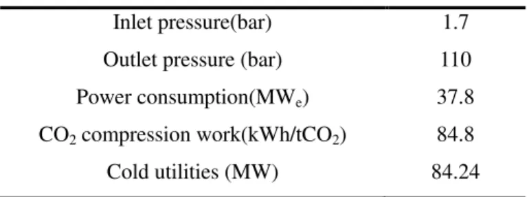
Inlet pressure(bar) 1.7
Outlet pressure (bar) 110
Power consumption(MWe) 37.8
CO2 compression work(kWh/tCO2) 84.8
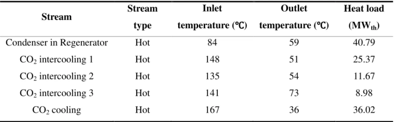
Table 7. Property of hot streams Stream Stream type Inlet temperature (℃℃℃℃) Outlet temperature (℃℃℃℃) Heat load (MWth)
Condenser in Regenerator Hot 84 59 40.79
CO2 intercooling 1 Hot 148 51 25.37
CO2 intercooling 2 Hot 135 54 11.67
CO2 intercooling 3 Hot 141 73 8.98
Table 8. Thermal performance of Cases with 3.64 bar steam extraction.
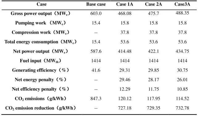
Case Base case Case 1A Case 2A Case3A
Gross power output((((MWe)))) 603.0 468.08 475.7 488.35
Pumping work ((((MWe)))) 15.4 15.8 15.8 15.8
Compression work((((MWe)))) -- 37.8 37.8 37.8
Total energy consumption((((MWe)))) 15.4 53.6 53.6 53.6 Net power output((((MWe)))) 587.6 414.48 422.1 434.75
Fuel input((((MWth)))) 1414 1414 1414 1414
Generating efficiency((((%)))) 41.6 29.31 29.85 30.75
Net energy penalty((((%)))) -- 29.46 28.17 26.01
Net efficiency penalty((((%)))) -- 12.29 11.75 10.85 CO2 emissions((((g/kWh)))) 847.3 120.12 117.95 114.52 CO2 emission reduction((((g/kWh)))) -- 727.18 729.35 732.78
Table 9. Thermal performance of Cases with steam extraction from IP-LP crossover at 9.1 bar
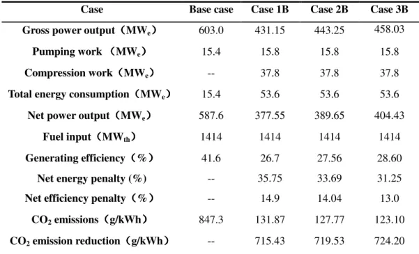
Case Base case Case 1B Case 2B Case 3B
Gross power output((((MWe)))) 603.0 431.15 443.25 458.03
Pumping work ((((MWe)))) 15.4 15.8 15.8 15.8
Compression work((((MWe)))) -- 37.8 37.8 37.8
Total energy consumption((((MWe)))) 15.4 53.6 53.6 53.6 Net power output((((MWe)))) 587.6 377.55 389.65 404.43
Fuel input((((MWth)))) 1414 1414 1414 1414
Generating efficiency((((%)))) 41.6 26.7 27.56 28.60
Net energy penalty (%) -- 35.75 33.69 31.25
Net efficiency penalty((((%)))) -- 14.9 14.04 13.0 CO2 emissions((((g/kWh)))) 847.3 131.87 127.77 123.10 CO2 emission reduction((((g/kWh)))) -- 715.43 719.53 724.20
Table 10. The performance of Case 4B with an auxiliary turbine
Case Base case Case 4B
Gross power output((((MWe)))) 603.0 503.98 Pumping work ((((MWe)))) 15.4 15.8 Compression work((((MWe)))) -- 37.8 Total energy consumption((((MWe)))) 15.4 53.6 Net power output((((MWe)))) 587.6 450.38
Fuel input((((MWth)))) 1414 1414 Generating efficiency((((%)))) 41.6 31.85
Net energy penalty (%) -- 23.35
Net efficiency penalty((((%)))) -- 9.75 CO2 emissions((((g/kWh)))) 847.3 110.55 CO2 emission reduction((((g/kWh)))) -- 736.75
Figure 4. Absorber diameter as function of the number of columns Figure 4. Absorber diameter as function of the number of columns Figure 4. Absorber diameter as function of the number of columns
Figure 5. Regenerator diameter as function of the number of columns Figure 5. Regenerator diameter as function of the number of columns Figure 5. Regenerator diameter as function of the number of columns
Figure
Figure 10. Flow diagram of